Injector SUZUKI JIMNY 2005 3.G Service Service Manual
[x] Cancel search | Manufacturer: SUZUKI, Model Year: 2005, Model line: JIMNY, Model: SUZUKI JIMNY 2005 3.GPages: 687, PDF Size: 13.38 MB
Page 631 of 687
Downloaded from www.Manualslib.com manuals search engine 6E-26 ENGINE AND EMISSION CONTROL SYSTEM
REMOVAL
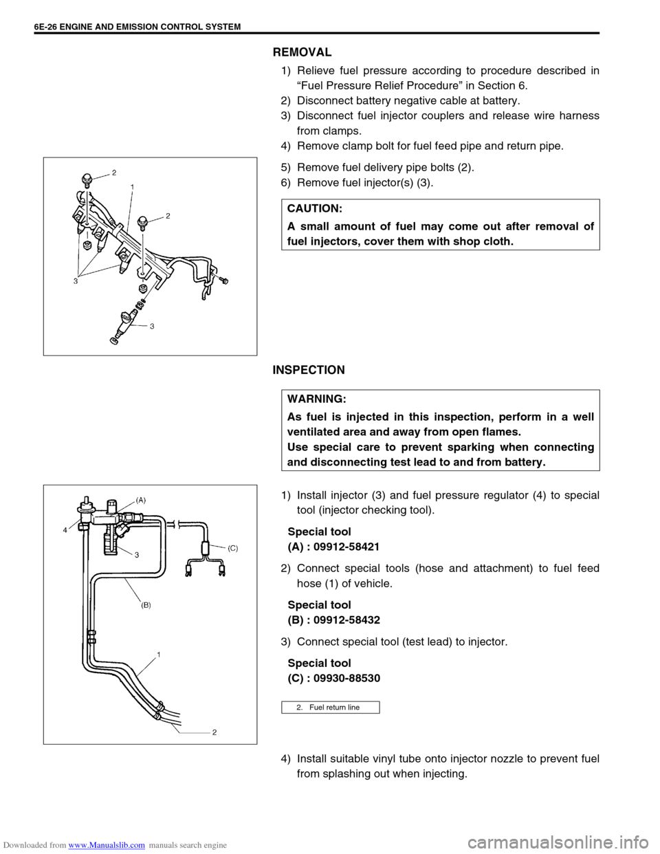
1) Relieve fuel pressure according to procedure described in
“Fuel Pressure Relief Procedure” in Section 6.
2) Disconnect battery negative cable at battery.
3) Disconnect fuel injector couplers and release wire harness
from clamps.
4) Remove clamp bolt for fuel feed pipe and return pipe.
5) Remove fuel delivery pipe bolts (2).
6) Remove fuel injector(s) (3).
INSPECTION
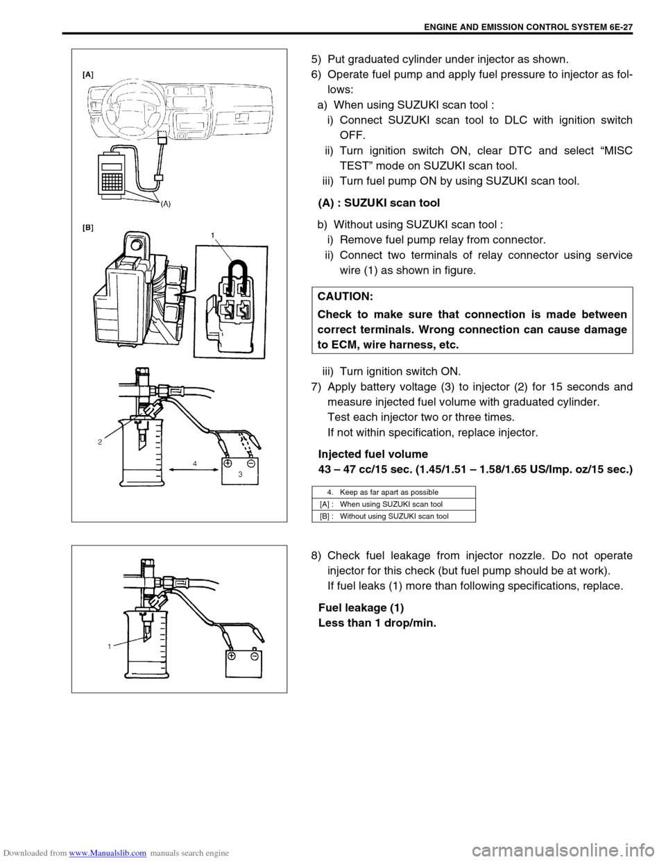
1) Install injector (3) and fuel pressure regulator (4) to special
tool (injector checking tool).
Special tool
(A) : 09912-58421
2) Connect special tools (hose and attachment) to fuel feed
hose (1) of vehicle.
Special tool
(B) : 09912-58432
3) Connect special tool (test lead) to injector.
Special tool
(C) : 09930-88530
4) Install suitable vinyl tube onto injector nozzle to prevent fuel
from splashing out when injecting. CAUTION:
A small amount of fuel may come out after removal of
fuel injectors, cover them with shop cloth.
WARNING:
As fuel is injected in this inspection, perform in a well
ventilated area and away from open flames.
Use special care to prevent sparking when connecting
and disconnecting test lead to and from battery.
2. Fuel return line
Page 632 of 687
Downloaded from www.Manualslib.com manuals search engine ENGINE AND EMISSION CONTROL SYSTEM 6E-27
5) Put graduated cylinder under injector as shown.
6) Operate fuel pump and apply fuel pressure to injector as fol-
lows:
a) When using SUZUKI scan tool :
i) Connect SUZUKI scan tool to DLC with ignition switch
OFF.
ii) Turn ignition switch ON, clear DTC and select “MISC
TEST” mode on SUZUKI scan tool.
iii) Turn fuel pump ON by using SUZUKI scan tool.
(A) : SUZUKI scan tool
b) Without using SUZUKI scan tool :
i) Remove fuel pump relay from connector.
ii) Connect two terminals of relay connector using service
wire (1) as shown in figure.
iii) Turn ignition switch ON.
7) Apply battery voltage (3) to injector (2) for 15 seconds and
measure injected fuel volume with graduated cylinder.
Test each injector two or three times.
If not within specification, replace injector.
Injected fuel volume
43 – 47 cc/15 sec. (1.45/1.51 – 1.58/1.65 US/Imp. oz/15 sec.)
8) Check fuel leakage from injector nozzle. Do not operate
injector for this check (but fuel pump should be at work).
If fuel leaks (1) more than following specifications, replace.
Fuel leakage (1)
Less than 1 drop/min. CAUTION:
Check to make sure that connection is made between
correct terminals. Wrong connection can cause damage
to ECM, wire harness, etc.
4. Keep as far apart as possible
[A] : When using SUZUKI scan tool
[B] : Without using SUZUKI scan tool
Page 633 of 687
Downloaded from www.Manualslib.com manuals search engine 6E-28 ENGINE AND EMISSION CONTROL SYSTEM
INSTALLATION
For installation, reverse removal procedure and note following
precautions.
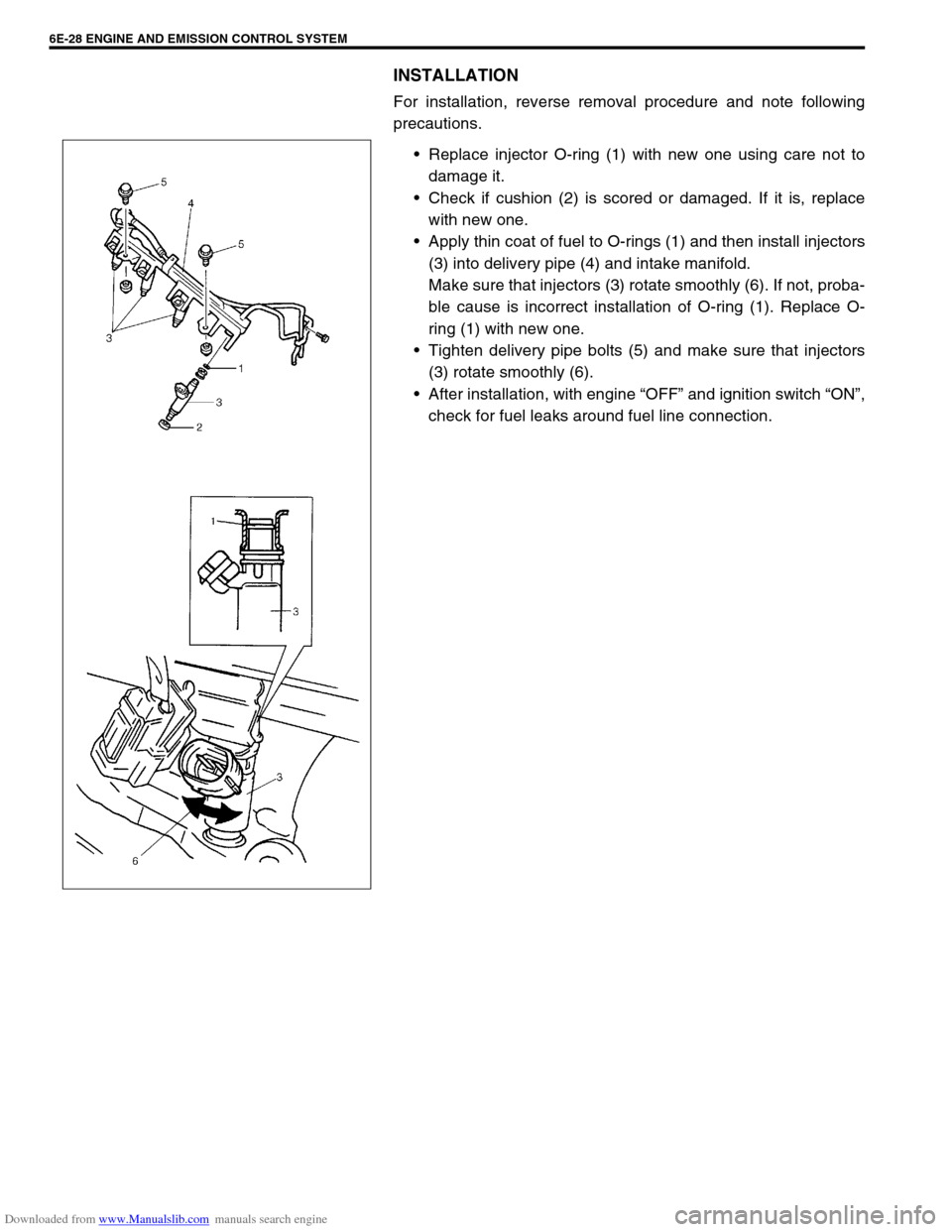
Replace injector O-ring (1) with new one using care not to
damage it.
Check if cushion (2) is scored or damaged. If it is, replace
with new one.
Apply thin coat of fuel to O-rings (1) and then install injectors
(3) into delivery pipe (4) and intake manifold.
Make sure that injectors (3) rotate smoothly (6). If not, proba-
ble cause is incorrect installation of O-ring (1). Replace O-
ring (1) with new one.
Tighten delivery pipe bolts (5) and make sure that injectors
(3) rotate smoothly (6).
After installation, with engine “OFF” and ignition switch “ON”,
check for fuel leaks around fuel line connection.
Page 642 of 687
Downloaded from www.Manualslib.com manuals search engine ENGINE AND EMISSION CONTROL SYSTEM 6E-37
Fuel cut operation
INSPECTION
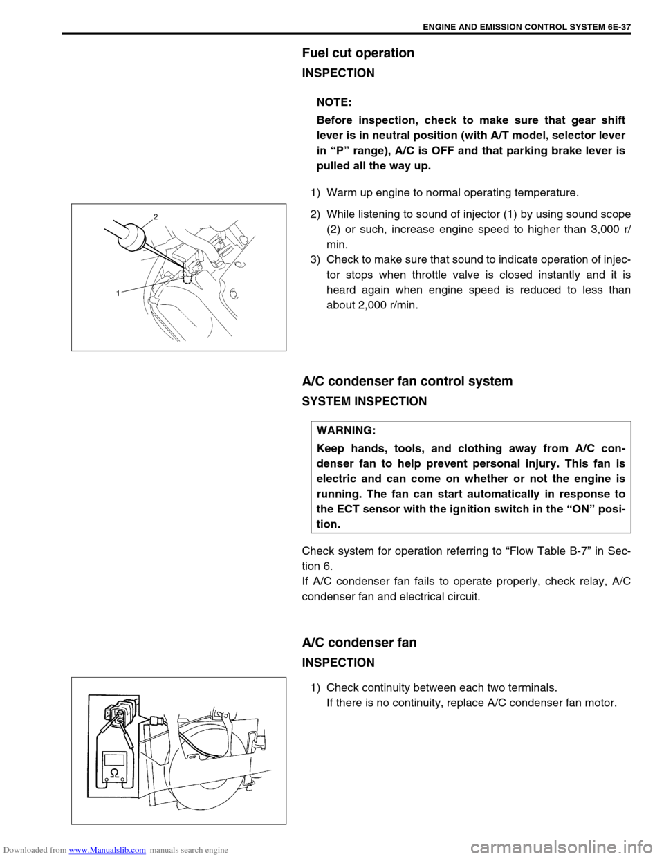
1) Warm up engine to normal operating temperature.
2) While listening to sound of injector (1) by using sound scope
(2) or such, increase engine speed to higher than 3,000 r/
min.
3) Check to make sure that sound to indicate operation of injec-
tor stops when throttle valve is closed instantly and it is
heard again when engine speed is reduced to less than
about 2,000 r/min.
A/C condenser fan control system
SYSTEM INSPECTION
Check system for operation referring to “Flow Table B-7” in Sec-
tion 6.
If A/C condenser fan fails to operate properly, check relay, A/C
condenser fan and electrical circuit.
A/C condenser fan
INSPECTION
1) Check continuity between each two terminals.
If there is no continuity, replace A/C condenser fan motor. NOTE:
Before inspection, check to make sure that gear shift
lever is in neutral position (with A/T model, selector lever
in “P” range), A/C is OFF and that parking brake lever is
pulled all the way up.
WARNING:
Keep hands, tools, and clothing away from A/C con-
denser fan to help prevent personal injury. This fan is
electric and can come on whether or not the engine is
running. The fan can start automatically in response to
the ECT sensor with the ignition switch in the “ON” posi-
tion.
Page 647 of 687
Downloaded from www.Manualslib.com manuals search engine 6E-42 ENGINE AND EMISSION CONTROL SYSTEM
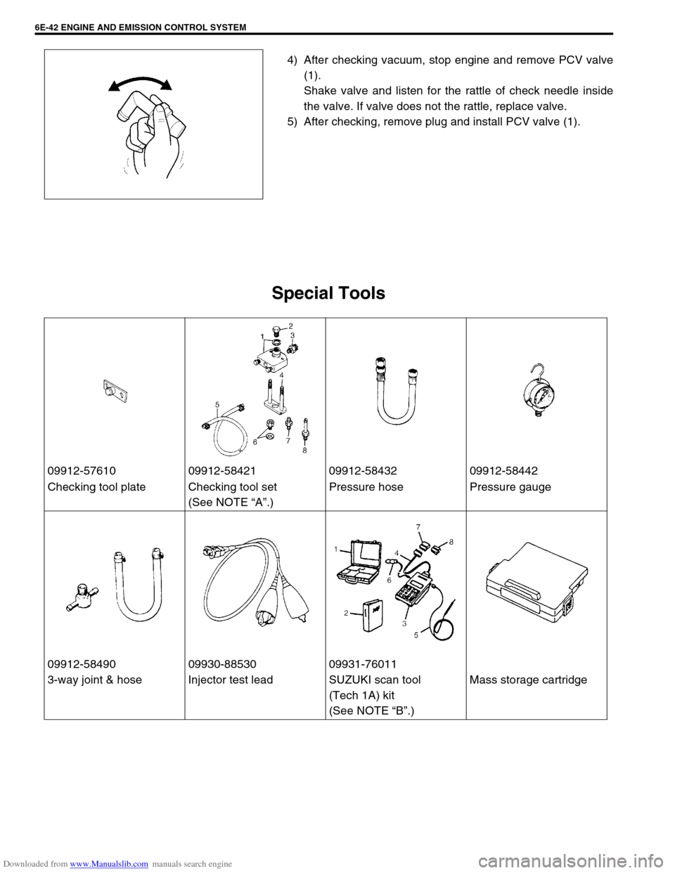
4) After checking vacuum, stop engine and remove PCV valve
(1).
Shake valve and listen for the rattle of check needle inside
the valve. If valve does not the rattle, replace valve.
5) After checking, remove plug and install PCV valve (1).
Special Tools
09912-57610 09912-58421 09912-58432 09912-58442
Checking tool plate Checking tool set
(See NOTE “A”.)Pressure hose Pressure gauge
09912-58490 09930-88530 09931-76011
3-way joint & hose Injector test lead SUZUKI scan tool
(Tech 1A) kit
(See NOTE “B”.)Mass storage cartridge
Page 654 of 687
Downloaded from www.Manualslib.com manuals search engine IGNITION SYSTEM (ELECTRONIC IGNITION SYSTEM 6F-5
On-Vehicle Service
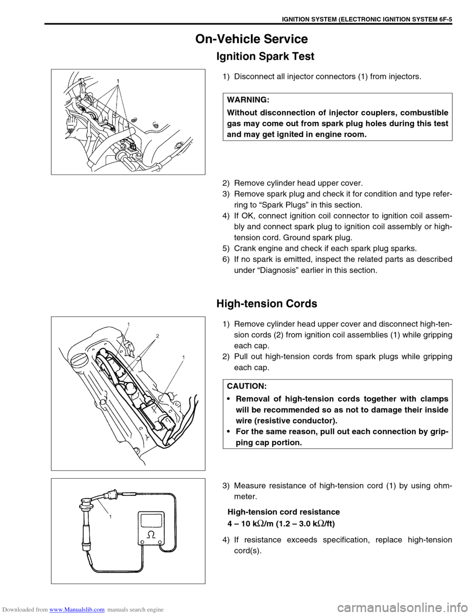
Ignition Spark Test
1) Disconnect all injector connectors (1) from injectors.
2) Remove cylinder head upper cover.
3) Remove spark plug and check it for condition and type refer-
ring to “Spark Plugs” in this section.
4) If OK, connect ignition coil connector to ignition coil assem-
bly and connect spark plug to ignition coil assembly or high-
tension cord. Ground spark plug.
5) Crank engine and check if each spark plug sparks.
6) If no spark is emitted, inspect the related parts as described
under “Diagnosis” earlier in this section.
High-tension Cords
1) Remove cylinder head upper cover and disconnect high-ten-
sion cords (2) from ignition coil assemblies (1) while gripping
each cap.
2) Pull out high-tension cords from spark plugs while gripping
each cap.
3) Measure resistance of high-tension cord (1) by using ohm-
meter.
High-tension cord resistance
4 – 10 k
Ω/m (1.2 – 3.0 kΩ/ft)
4) If resistance exceeds specification, replace high-tension
cord(s). WARNING:
Without disconnection of injector couplers, combustible
gas may come out from spark plug holes during this test
and may get ignited in engine room.
CAUTION:
Removal of high-tension cords together with clamps
will be recommended so as not to damage their inside
wire (resistive conductor).
For the same reason, pull out each connection by grip-
ping cap portion.