clock SUZUKI JIMNY 2005 3.G Service Workshop Manual
[x] Cancel search | Manufacturer: SUZUKI, Model Year: 2005, Model line: JIMNY, Model: SUZUKI JIMNY 2005 3.GPages: 687, PDF Size: 13.38 MB
Page 76 of 687
Downloaded from www.Manualslib.com manuals search engine AIR CONDITIONING (OPTIONAL) 1B-15
Compressor Drive Belt
INSPECTION
Check belt for wear and cracks, and replace as required.
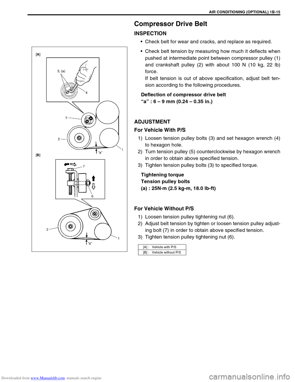
Check belt tension by measuring how much it deflects when
pushed at intermediate point between compressor pulley (1)
and crankshaft pulley (2) with about 100 N (10 kg, 22 lb)
force.
If belt tension is out of above specification, adjust belt ten-
sion according to the following procedures.
Deflection of compressor drive belt
“a” : 6 – 9 mm (0.24 – 0.35 in.)
ADJUSTMENT
For Vehicle With P/S
1) Loosen tension pulley bolts (3) and set hexagon wrench (4)
to hexagon hole.
2) Turn tension pulley (5) counterclockwise by hexagon wrench
in order to obtain above specified tension.
3) Tighten tension pulley bolts (3) to specified torque.
Tightening torque
Tension pulley bolts
(a) : 25N·m (2.5 kg-m, 18.0 lb-ft)
For Vehicle Without P/S
1) Loosen tension pulley tightening nut (6).
2) Adjust belt tension by tighten or loosen tension pulley adjust-
ing bolt (7) in order to obtain above specified tension.
3) Tighten tension pulley tightening nut (6).
[A] : Vehicle with P/S
[B] : Vehicle without P/S
Page 87 of 687
Downloaded from www.Manualslib.com manuals search engine 1B-26 AIR CONDITIONING (OPTIONAL)
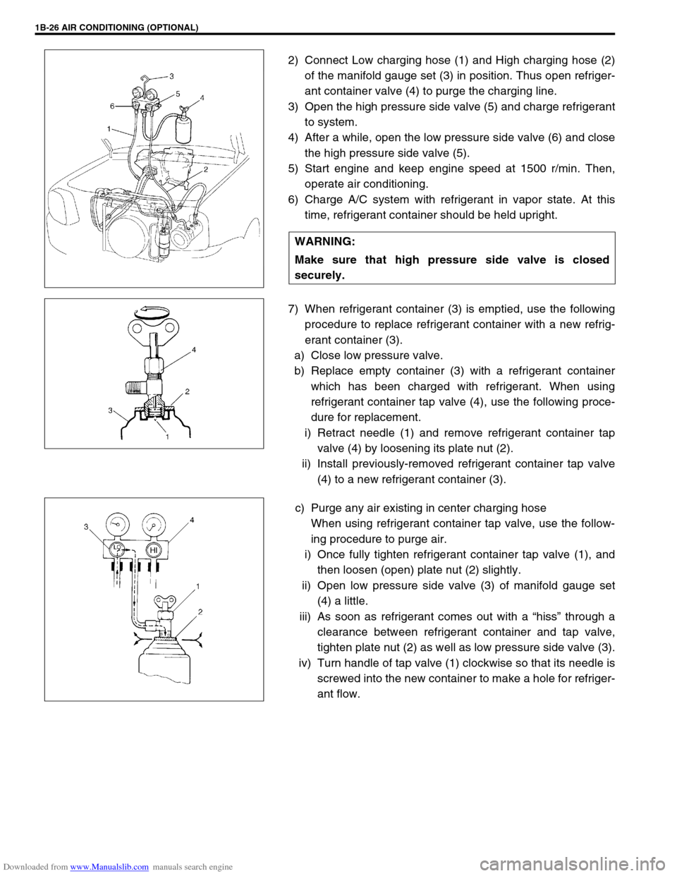
2) Connect Low charging hose (1) and High charging hose (2)
of the manifold gauge set (3) in position. Thus open refriger-
ant container valve (4) to purge the charging line.
3) Open the high pressure side valve (5) and charge refrigerant
to system.
4) After a while, open the low pressure side valve (6) and close
the high pressure side valve (5).
5) Start engine and keep engine speed at 1500 r/min. Then,
operate air conditioning.
6) Charge A/C system with refrigerant in vapor state. At this
time, refrigerant container should be held upright.
7) When refrigerant container (3) is emptied, use the following
procedure to replace refrigerant container with a new refrig-
erant container (3).
a) Close low pressure valve.
b) Replace empty container (3) with a refrigerant container
which has been charged with refrigerant. When using
refrigerant container tap valve (4), use the following proce-
dure for replacement.
i) Retract needle (1) and remove refrigerant container tap
valve (4) by loosening its plate nut (2).
ii) Install previously-removed refrigerant container tap valve
(4) to a new refrigerant container (3).
c) Purge any air existing in center charging hose
When using refrigerant container tap valve, use the follow-
ing procedure to purge air.
i) Once fully tighten refrigerant container tap valve (1), and
then loosen (open) plate nut (2) slightly.
ii) Open low pressure side valve (3) of manifold gauge set
(4) a little.
iii) As soon as refrigerant comes out with a “hiss” through a
clearance between refrigerant container and tap valve,
tighten plate nut (2) as well as low pressure side valve (3).
iv) Turn handle of tap valve (1) clockwise so that its needle is
screwed into the new container to make a hole for refriger-
ant flow. WARNING:
Make sure that high pressure side valve is closed
securely.
Page 137 of 687
Downloaded from www.Manualslib.com manuals search engine 3B1-6 POWER STEERING (P/S) SYSTEM (If equipped)
Power Steering Belt Check
INSPECTION
Check that belt is free from any damage and properly fitted
in pulley groove.
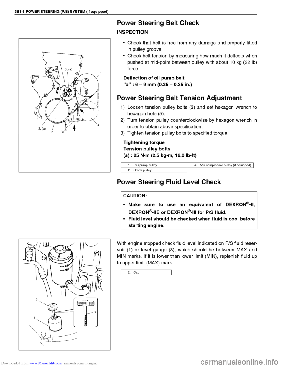
Check belt tension by measuring how much it deflects when
pushed at mid-point between pulley with about 10 kg (22 lb)
force.
Deflection of oil pump belt
“a” : 6 – 9 mm (0.25 – 0.35 in.)
Power Steering Belt Tension Adjustment
1) Loosen tension pulley bolts (3) and set hexagon wrench to
hexagon hole (5).
2) Turn tension pulley counterclockwise by hexagon wrench in
order to obtain above specification.
3) Tighten tension pulley bolts to specified torque.
Tightening torque
Tension pulley bolts
(a) : 25 N·m (2.5 kg-m, 18.0 lb-ft)
Power Steering Fluid Level Check
With engine stopped check fluid level indicated on P/S fluid reser-
voir (1) or level gauge (3), which should be between MAX and
MIN marks. If it is lower than lower limit (MIN), replenish fluid up
to upper limit (MAX) mark.
1. P/S pump pulley 4. A/C compressor pulley (if equipped)
2. Crank pulley
CAUTION:
Make sure to use an equivalent of DEXRON
®-II,
DEXRON
®-IIE or DEXRON®-III for P/S fluid.
Fluid level should be checked when fluid is cool before
starting engine.
2. Cap
Page 149 of 687
Downloaded from www.Manualslib.com manuals search engine 3B1-18 POWER STEERING (P/S) SYSTEM (If equipped)
INSTALLATION
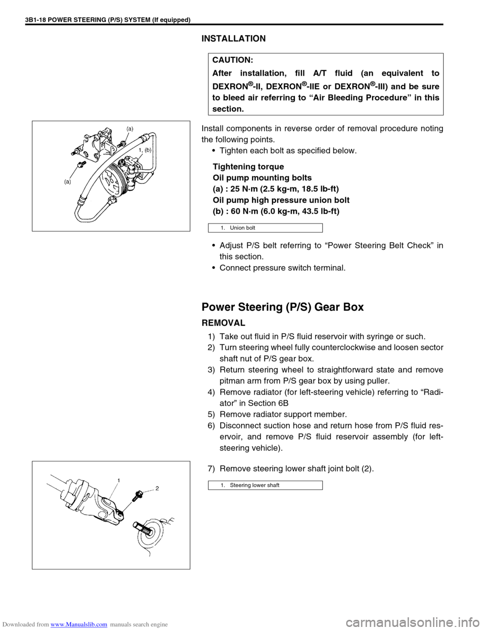
Install components in reverse order of removal procedure noting
the following points.
Tighten each bolt as specified below.
Tightening torque
Oil pump mounting bolts
(a) : 25 N·m (2.5 kg-m, 18.5 lb-ft)
Oil pump high pressure union bolt
(b) : 60 N·m (6.0 kg-m, 43.5 lb-ft)
Adjust P/S belt referring to “Power Steering Belt Check” in
this section.
Connect pressure switch terminal.
Power Steering (P/S) Gear Box
REMOVAL
1) Take out fluid in P/S fluid reservoir with syringe or such.
2) Turn steering wheel fully counterclockwise and loosen sector
shaft nut of P/S gear box.
3) Return steering wheel to straightforward state and remove
pitman arm from P/S gear box by using puller.
4) Remove radiator (for left-steering vehicle) referring to “Radi-
ator” in Section 6B
5) Remove radiator support member.
6) Disconnect suction hose and return hose from P/S fluid res-
ervoir, and remove P/S fluid reservoir assembly (for left-
steering vehicle).
7) Remove steering lower shaft joint bolt (2).CAUTION:
After installation, fill A/T fluid (an equivalent to
DEXRON
®-II, DEXRON®-IIE or DEXRON®-III) and be sure
to bleed air referring to “Air Bleeding Procedure” in this
section.
1. Union bolt
1. Steering lower shaft
Page 158 of 687
Downloaded from www.Manualslib.com manuals search engine STEERING WHEEL AND COLUMN 3C-5
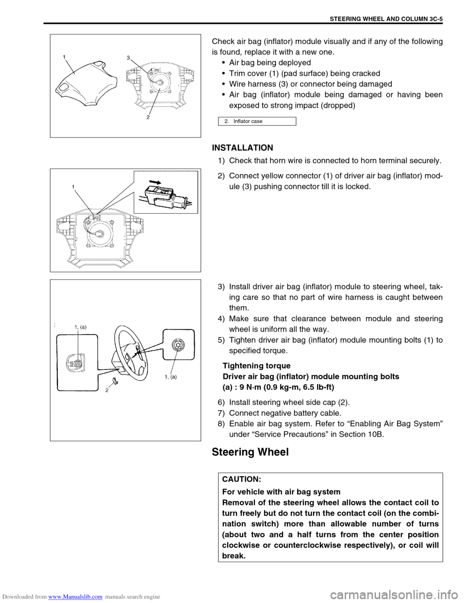
Check air bag (inflator) module visually and if any of the following
is found, replace it with a new one.
Air bag being deployed
Trim cover (1) (pad surface) being cracked
Wire harness (3) or connector being damaged
Air bag (inflator) module being damaged or having been
exposed to strong impact (dropped)
INSTALLATION
1) Check that horn wire is connected to horn terminal securely.
2) Connect yellow connector (1) of driver air bag (inflator) mod-
ule (3) pushing connector till it is locked.
3) Install driver air bag (inflator) module to steering wheel, tak-
ing care so that no part of wire harness is caught between
them.
4) Make sure that clearance between module and steering
wheel is uniform all the way.
5) Tighten driver air bag (inflator) module mounting bolts (1) to
specified torque.
Tightening torque
Driver air bag (inflator) module mounting bolts
(a) : 9 N·m (0.9 kg-m, 6.5 lb-ft)
6) Install steering wheel side cap (2).
7) Connect negative battery cable.
8) Enable air bag system. Refer to “Enabling Air Bag System”
under “Service Precautions” in Section 10B.
Steering Wheel
2. Inflator case
CAUTION:
For vehicle with air bag system
Removal of the steering wheel allows the contact coil to
turn freely but do not turn the contact coil (on the combi-
nation switch) more than allowable number of turns
(about two and a half turns from the center position
clockwise or counterclockwise respectively), or coil will
break.
Page 161 of 687
Downloaded from www.Manualslib.com manuals search engine 3C-8 STEERING WHEEL AND COLUMN
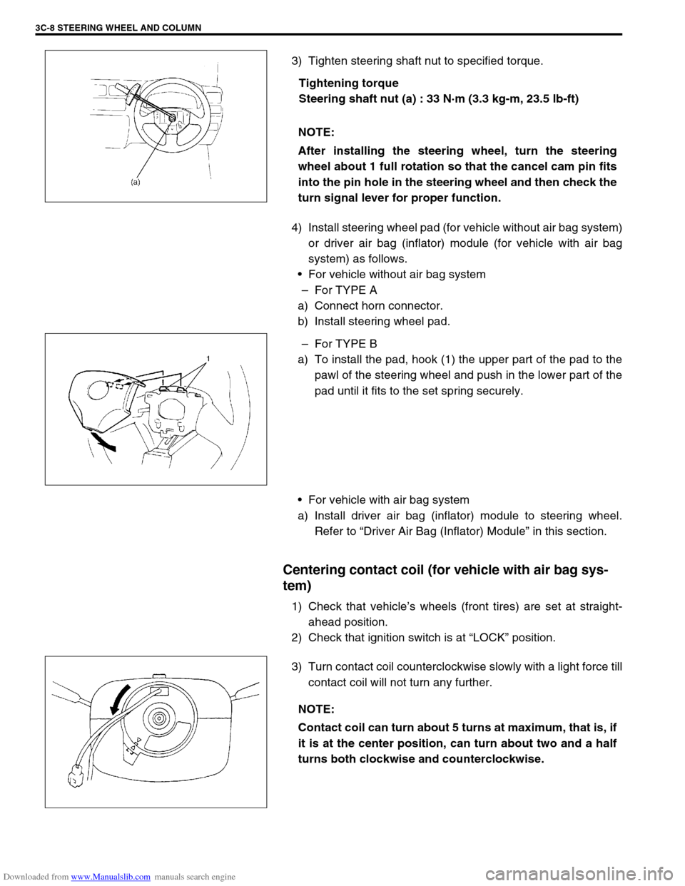
3) Tighten steering shaft nut to specified torque.
Tightening torque
Steering shaft nut (a) : 33 N·m (3.3 kg-m, 23.5 lb-ft)
4) Install steering wheel pad (for vehicle without air bag system)
or driver air bag (inflator) module (for vehicle with air bag
system) as follows.
For vehicle without air bag system
–For TYPE A
a) Connect horn connector.
b) Install steering wheel pad.
–For TYPE B
a) To install the pad, hook (1) the upper part of the pad to the
pawl of the steering wheel and push in the lower part of the
pad until it fits to the set spring securely.
For vehicle with air bag system
a) Install driver air bag (inflator) module to steering wheel.
Refer to “Driver Air Bag (Inflator) Module” in this section.
Centering contact coil (for vehicle with air bag sys-
tem)
1) Check that vehicle’s wheels (front tires) are set at straight-
ahead position.
2) Check that ignition switch is at “LOCK” position.
3) Turn contact coil counterclockwise slowly with a light force till
contact coil will not turn any further. NOTE:
After installing the steering wheel, turn the steering
wheel about 1 full rotation so that the cancel cam pin fits
into the pin hole in the steering wheel and then check the
turn signal lever for proper function.
NOTE:
Contact coil can turn about 5 turns at maximum, that is, if
it is at the center position, can turn about two and a half
turns both clockwise and counterclockwise.
Page 162 of 687
Downloaded from www.Manualslib.com manuals search engine STEERING WHEEL AND COLUMN 3C-9
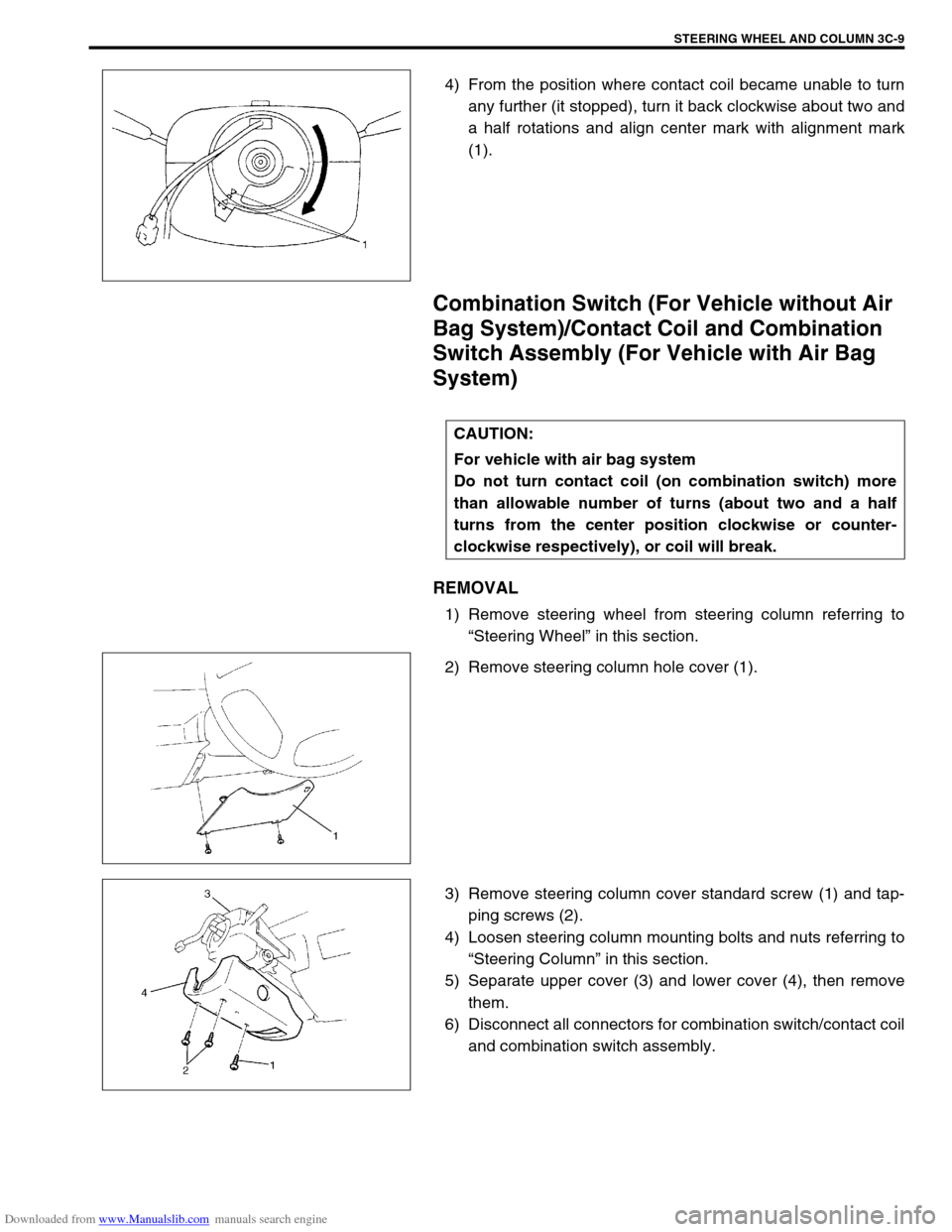
4) From the position where contact coil became unable to turn
any further (it stopped), turn it back clockwise about two and
a half rotations and align center mark with alignment mark
(1).
Combination Switch (For Vehicle without Air
Bag System)/Contact Coil and Combination
Switch Assembly (For Vehicle with Air Bag
System)
REMOVAL
1) Remove steering wheel from steering column referring to
“Steering Wheel” in this section.
2) Remove steering column hole cover (1).
3) Remove steering column cover standard screw (1) and tap-
ping screws (2).
4) Loosen steering column mounting bolts and nuts referring to
“Steering Column” in this section.
5) Separate upper cover (3) and lower cover (4), then remove
them.
6) Disconnect all connectors for combination switch/contact coil
and combination switch assembly.
CAUTION:
For vehicle with air bag system
Do not turn contact coil (on combination switch) more
than allowable number of turns (about two and a half
turns from the center position clockwise or counter-
clockwise respectively), or coil will break.
Page 490 of 687
Downloaded from www.Manualslib.com manuals search engine ENGINE MECHANICAL (M13 ENGINE) 6A1-9
Valve Lash (Clearance)
1) Remove negative cable at battery.
2) Remove cylinder head cover referring to “Cylinder Head
Cover” in this section.
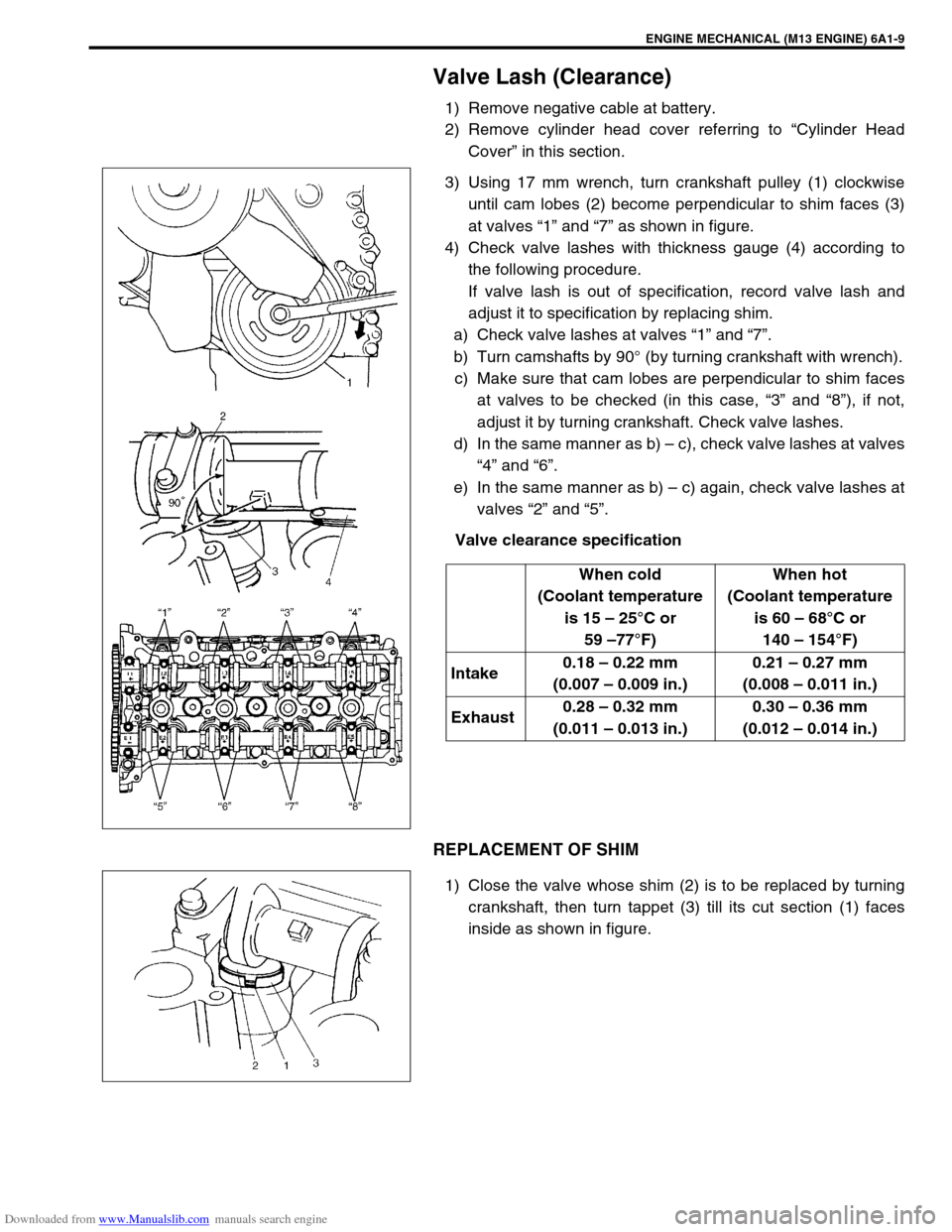
3) Using 17 mm wrench, turn crankshaft pulley (1) clockwise
until cam lobes (2) become perpendicular to shim faces (3)
at valves “1” and “7” as shown in figure.
4) Check valve lashes with thickness gauge (4) according to
the following procedure.
If valve lash is out of specification, record valve lash and
adjust it to specification by replacing shim.
a) Check valve lashes at valves “1” and “7”.
b) Turn camshafts by 90° (by turning crankshaft with wrench).
c) Make sure that cam lobes are perpendicular to shim faces
at valves to be checked (in this case, “3” and “8”), if not,
adjust it by turning crankshaft. Check valve lashes.
d) In the same manner as b) – c), check valve lashes at valves
“4” and “6”.
e) In the same manner as b) – c) again, check valve lashes at
valves “2” and “5”.
Valve clearance specification
REPLACEMENT OF SHIM
1) Close the valve whose shim (2) is to be replaced by turning
crankshaft, then turn tappet (3) till its cut section (1) faces
inside as shown in figure.When cold
(Coolant temperature
is 15 – 25°C or
59 –77°F)When hot
(Coolant temperature
is 60 – 68°C or
140 – 154°F)
Intake0.18 – 0.22 mm
(0.007 – 0.009 in.)0.21 – 0.27 mm
(0.008 – 0.011 in.)
Exhaust0.28 – 0.32 mm
(0.011 – 0.013 in.)0.30 – 0.36 mm
(0.012 – 0.014 in.)
Page 491 of 687
Downloaded from www.Manualslib.com manuals search engine 6A1-10 ENGINE MECHANICAL (M13 ENGINE)
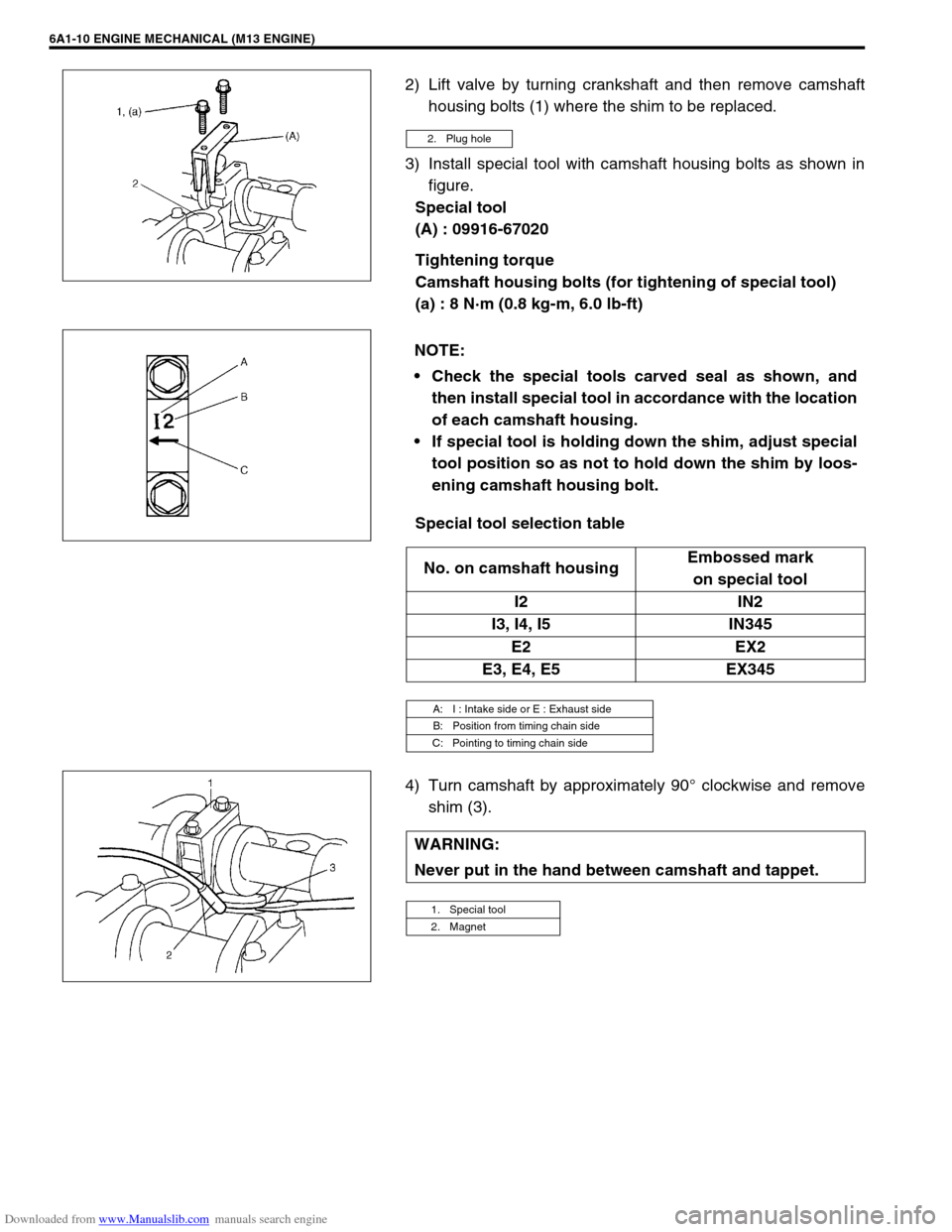
2) Lift valve by turning crankshaft and then remove camshaft
housing bolts (1) where the shim to be replaced.
3) Install special tool with camshaft housing bolts as shown in
figure.
Special tool
(A) : 09916-67020
Tightening torque
Camshaft housing bolts (for tightening of special tool)
(a) : 8 N·m (0.8 kg-m, 6.0 lb-ft)
Special tool selection table
4) Turn camshaft by approximately 90° clockwise and remove
shim (3).
2. Plug hole
NOTE:
Check the special tools carved seal as shown, and
then install special tool in accordance with the location
of each camshaft housing.
If special tool is holding down the shim, adjust special
tool position so as not to hold down the shim by loos-
ening camshaft housing bolt.
No. on camshaft housingEmbossed mark
on special tool
I2 IN2
I3, I4, I5 IN345
E2 EX2
E3, E4, E5 EX345
A: I : Intake side or E : Exhaust side
B: Position from timing chain side
C: Pointing to timing chain side
WARNING:
Never put in the hand between camshaft and tappet.
1. Special tool
2. Magnet
Page 493 of 687
Downloaded from www.Manualslib.com manuals search engine 6A1-12 ENGINE MECHANICAL (M13 ENGINE)
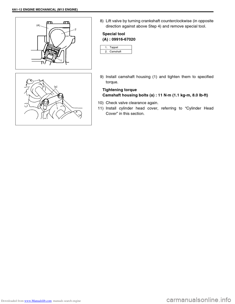
8) Lift valve by turning crankshaft counterclockwise (in opposite
direction against above Step 4) and remove special tool.
Special tool
(A) : 09916-67020
9) Install camshaft housing (1) and tighten them to specified
torque.
Tightening torque
Camshaft housing bolts (a) : 11 N·m (1.1 kg-m, 8.0 lb-ft)
10) Check valve clearance again.
11) Install cylinder head cover, referring to “Cylinder Head
Cover” in this section.
1. Tappet
2. Camshaft