pressure SUZUKI JIMNY 2005 3.G Service Service Manual
[x] Cancel search | Manufacturer: SUZUKI, Model Year: 2005, Model line: JIMNY, Model: SUZUKI JIMNY 2005 3.GPages: 687, PDF Size: 13.38 MB
Page 141 of 687
Downloaded from www.Manualslib.com manuals search engine 3B1-10 POWER STEERING (P/S) SYSTEM (If equipped)
Hydraulic Pressure In P/S Circuit Check
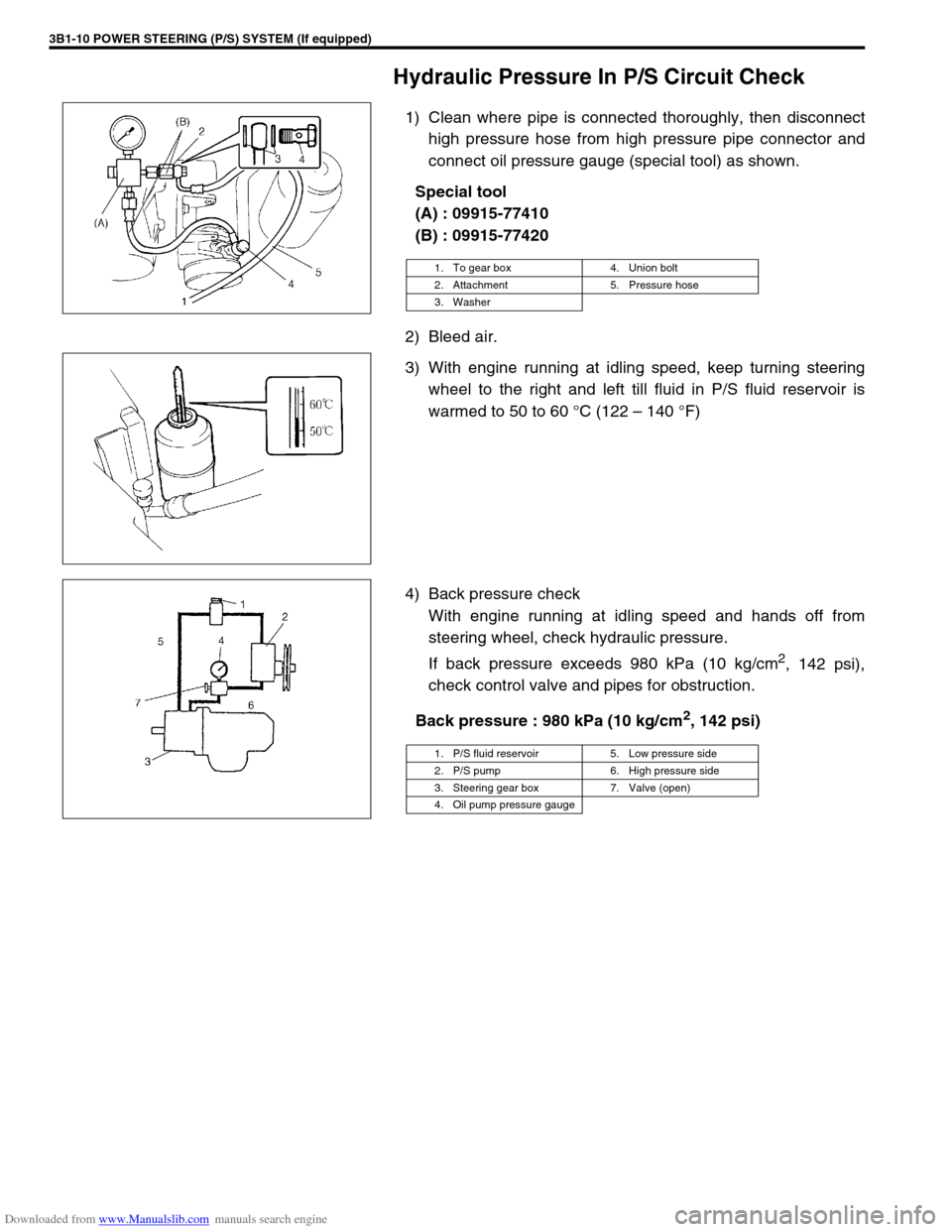
1) Clean where pipe is connected thoroughly, then disconnect
high pressure hose from high pressure pipe connector and
connect oil pressure gauge (special tool) as shown.
Special tool
(A) : 09915-77410
(B) : 09915-77420
2) Bleed air.
3) With engine running at idling speed, keep turning steering
wheel to the right and left till fluid in P/S fluid reservoir is
warmed to 50 to 60 °C (122 – 140 °F)
4) Back pressure check
With engine running at idling speed and hands off from
steering wheel, check hydraulic pressure.
If back pressure exceeds 980 kPa (10 kg/cm
2, 142 psi),
check control valve and pipes for obstruction.
Back pressure : 980 kPa (10 kg/cm
2, 142 psi)
1. To gear box 4. Union bolt
2. Attachment 5. Pressure hose
3. Washer
1. P/S fluid reservoir 5. Low pressure side
2. P/S pump 6. High pressure side
3. Steering gear box 7. Valve (open)
4. Oil pump pressure gauge
Page 142 of 687
Downloaded from www.Manualslib.com manuals search engine POWER STEERING (P/S) SYSTEM (If equipped) 3B1-11
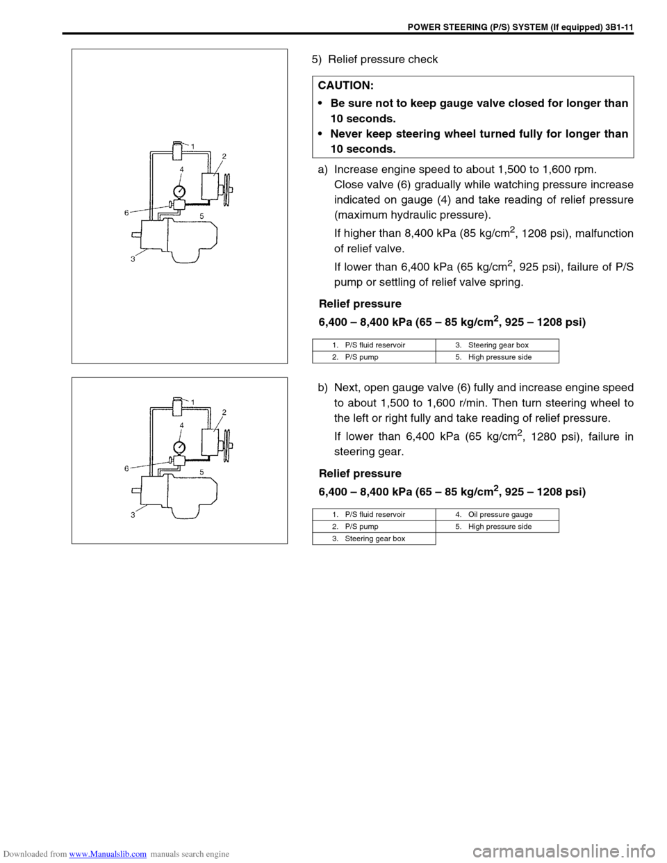
5) Relief pressure check
a) Increase engine speed to about 1,500 to 1,600 rpm.
Close valve (6) gradually while watching pressure increase
indicated on gauge (4) and take reading of relief pressure
(maximum hydraulic pressure).
If higher than 8,400 kPa (85 kg/cm
2, 1208 psi), malfunction
of relief valve.
If lower than 6,400 kPa (65 kg/cm
2, 925 psi), failure of P/S
pump or settling of relief valve spring.
Relief pressure
6,400 – 8,400 kPa (65 – 85 kg/cm
2, 925 – 1208 psi)
b) Next, open gauge valve (6) fully and increase engine speed
to about 1,500 to 1,600 r/min. Then turn steering wheel to
the left or right fully and take reading of relief pressure.
If lower than 6,400 kPa (65 kg/cm
2, 1280 psi), failure in
steering gear.
Relief pressure
6,400 – 8,400 kPa (65 – 85 kg/cm
2, 925 – 1208 psi) CAUTION:
Be sure not to keep gauge valve closed for longer than
10 seconds.
Never keep steering wheel turned fully for longer than
10 seconds.
1. P/S fluid reservoir 3. Steering gear box
2. P/S pump 5. High pressure side
1. P/S fluid reservoir 4. Oil pressure gauge
2. P/S pump 5. High pressure side
3. Steering gear box
Page 143 of 687
Downloaded from www.Manualslib.com manuals search engine 3B1-12 POWER STEERING (P/S) SYSTEM (If equipped)
On-Vehicle Service
Power Steering Belt
REMOVAL
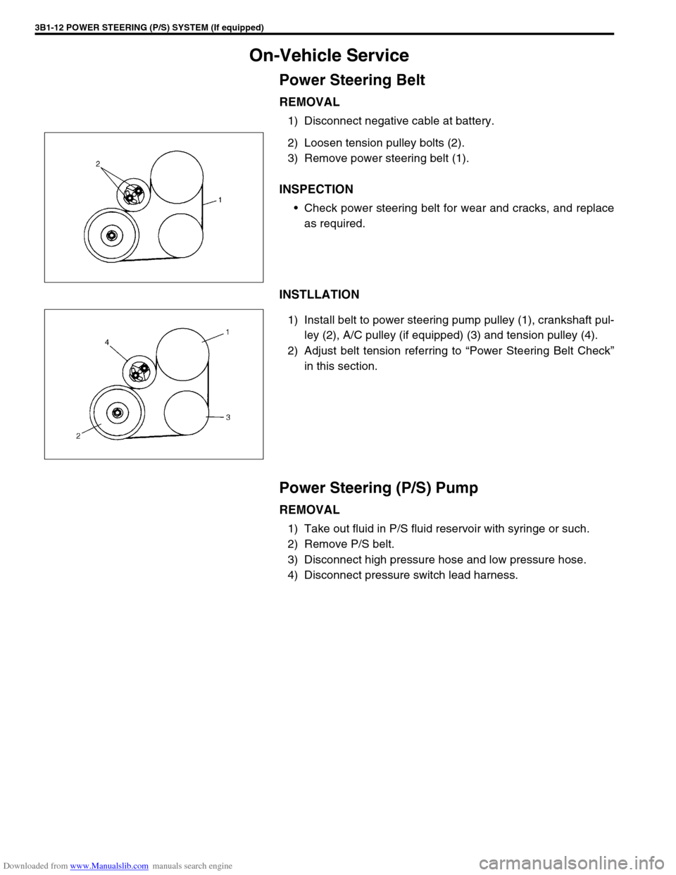
1) Disconnect negative cable at battery.
2) Loosen tension pulley bolts (2).
3) Remove power steering belt (1).
INSPECTION
Check power steering belt for wear and cracks, and replace
as required.
INSTLLATION
1) Install belt to power steering pump pulley (1), crankshaft pul-
ley (2), A/C pulley (if equipped) (3) and tension pulley (4).
2) Adjust belt tension referring to “Power Steering Belt Check”
in this section.
Power Steering (P/S) Pump
REMOVAL
1) Take out fluid in P/S fluid reservoir with syringe or such.
2) Remove P/S belt.
3) Disconnect high pressure hose and low pressure hose.
4) Disconnect pressure switch lead harness.
Page 144 of 687
Downloaded from www.Manualslib.com manuals search engine POWER STEERING (P/S) SYSTEM (If equipped) 3B1-13
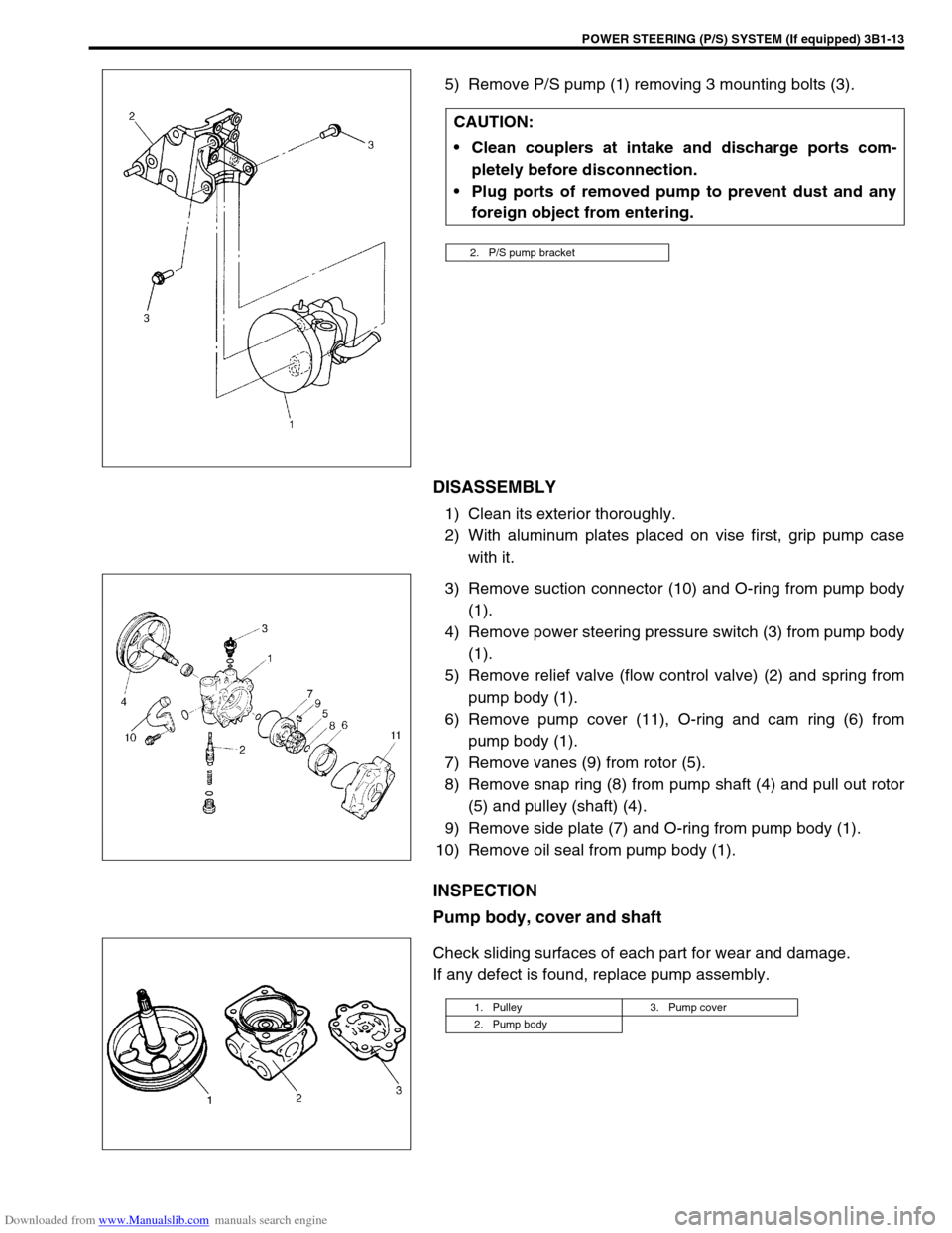
5) Remove P/S pump (1) removing 3 mounting bolts (3).
DISASSEMBLY
1) Clean its exterior thoroughly.
2) With aluminum plates placed on vise first, grip pump case
with it.
3) Remove suction connector (10) and O-ring from pump body
(1).
4) Remove power steering pressure switch (3) from pump body
(1).
5) Remove relief valve (flow control valve) (2) and spring from
pump body (1).
6) Remove pump cover (11), O-ring and cam ring (6) from
pump body (1).
7) Remove vanes (9) from rotor (5).
8) Remove snap ring (8) from pump shaft (4) and pull out rotor
(5) and pulley (shaft) (4).
9) Remove side plate (7) and O-ring from pump body (1).
10) Remove oil seal from pump body (1).
INSPECTION
Pump body, cover and shaft
Check sliding surfaces of each part for wear and damage.
If any defect is found, replace pump assembly.CAUTION:
Clean couplers at intake and discharge ports com-
pletely before disconnection.
Plug ports of removed pump to prevent dust and any
foreign object from entering.
2. P/S pump bracket
1. Pulley 3. Pump cover
2. Pump body
Page 148 of 687
Downloaded from www.Manualslib.com manuals search engine POWER STEERING (P/S) SYSTEM (If equipped) 3B1-17
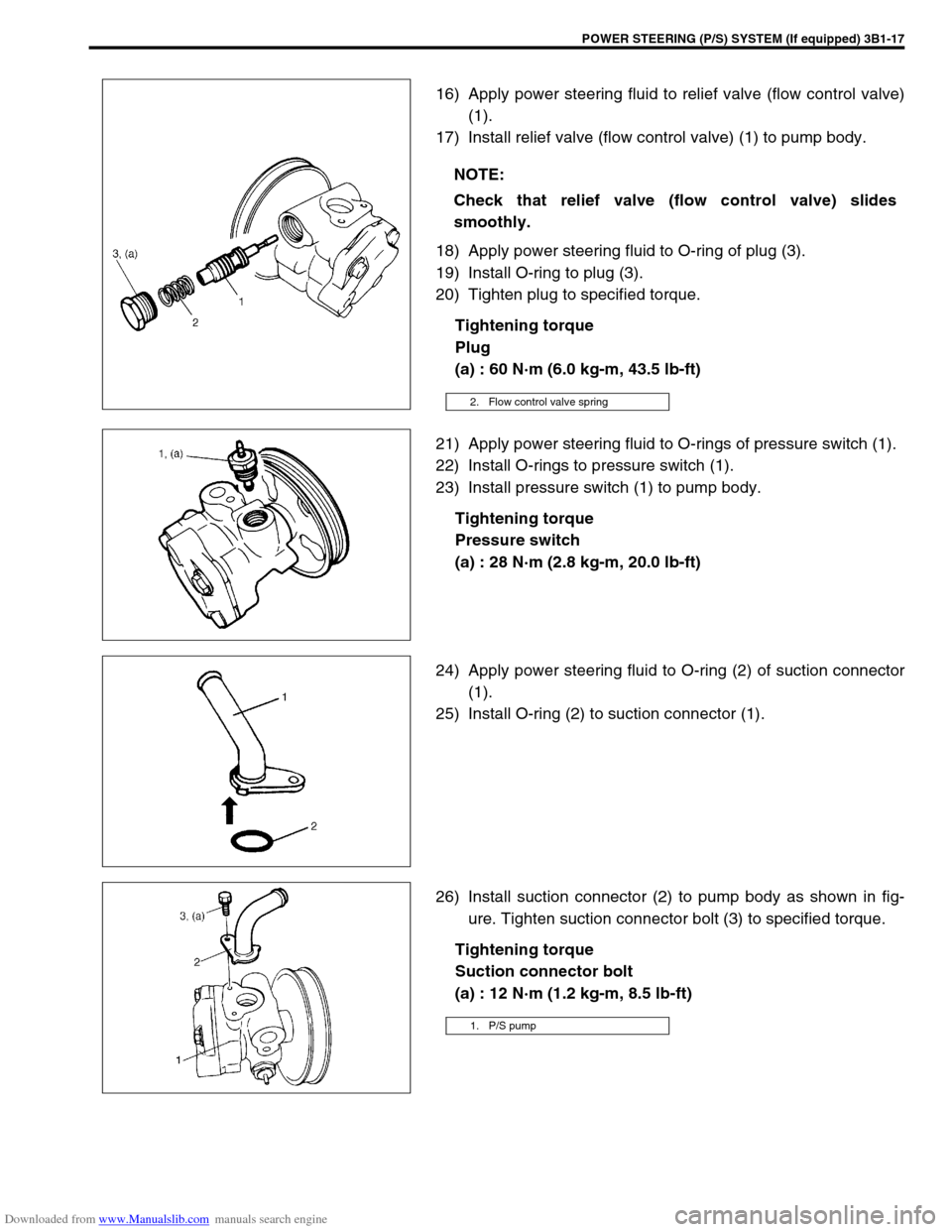
16) Apply power steering fluid to relief valve (flow control valve)
(1).
17) Install relief valve (flow control valve) (1) to pump body.
18) Apply power steering fluid to O-ring of plug (3).
19) Install O-ring to plug (3).
20) Tighten plug to specified torque.
Tightening torque
Plug
(a) : 60 N·m (6.0 kg-m, 43.5 lb-ft)
21) Apply power steering fluid to O-rings of pressure switch (1).
22) Install O-rings to pressure switch (1).
23) Install pressure switch (1) to pump body.
Tightening torque
Pressure switch
(a) : 28 N·m (2.8 kg-m, 20.0 lb-ft)
24) Apply power steering fluid to O-ring (2) of suction connector
(1).
25) Install O-ring (2) to suction connector (1).
26) Install suction connector (2) to pump body as shown in fig-
ure. Tighten suction connector bolt (3) to specified torque.
Tightening torque
Suction connector bolt
(a) : 12 N·m (1.2 kg-m, 8.5 lb-ft) NOTE:
Check that relief valve (flow control valve) slides
smoothly.
2. Flow control valve spring
1. P/S pump
Page 149 of 687
Downloaded from www.Manualslib.com manuals search engine 3B1-18 POWER STEERING (P/S) SYSTEM (If equipped)
INSTALLATION
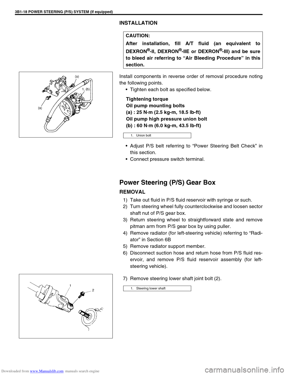
Install components in reverse order of removal procedure noting
the following points.
Tighten each bolt as specified below.
Tightening torque
Oil pump mounting bolts
(a) : 25 N·m (2.5 kg-m, 18.5 lb-ft)
Oil pump high pressure union bolt
(b) : 60 N·m (6.0 kg-m, 43.5 lb-ft)
Adjust P/S belt referring to “Power Steering Belt Check” in
this section.
Connect pressure switch terminal.
Power Steering (P/S) Gear Box
REMOVAL
1) Take out fluid in P/S fluid reservoir with syringe or such.
2) Turn steering wheel fully counterclockwise and loosen sector
shaft nut of P/S gear box.
3) Return steering wheel to straightforward state and remove
pitman arm from P/S gear box by using puller.
4) Remove radiator (for left-steering vehicle) referring to “Radi-
ator” in Section 6B
5) Remove radiator support member.
6) Disconnect suction hose and return hose from P/S fluid res-
ervoir, and remove P/S fluid reservoir assembly (for left-
steering vehicle).
7) Remove steering lower shaft joint bolt (2).CAUTION:
After installation, fill A/T fluid (an equivalent to
DEXRON
®-II, DEXRON®-IIE or DEXRON®-III) and be sure
to bleed air referring to “Air Bleeding Procedure” in this
section.
1. Union bolt
1. Steering lower shaft
Page 150 of 687
Downloaded from www.Manualslib.com manuals search engine POWER STEERING (P/S) SYSTEM (If equipped) 3B1-19
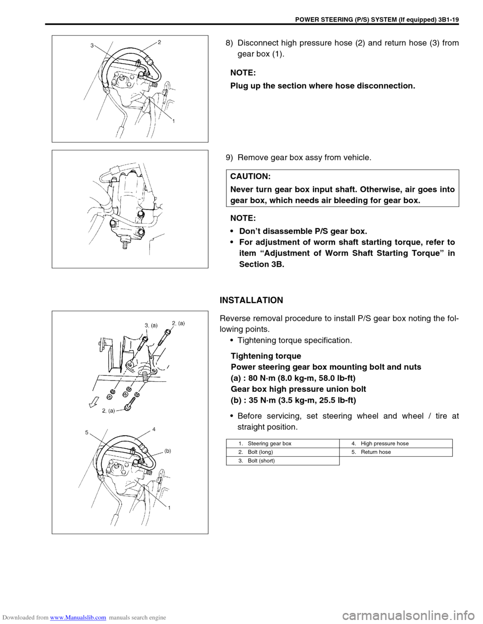
8) Disconnect high pressure hose (2) and return hose (3) from
gear box (1).
9) Remove gear box assy from vehicle.
INSTALLATION
Reverse removal procedure to install P/S gear box noting the fol-
lowing points.
Tightening torque specification.
Tightening torque
Power steering gear box mounting bolt and nuts
(a) : 80 N·m (8.0 kg-m, 58.0 lb-ft)
Gear box high pressure union bolt
(b) : 35 N·m (3.5 kg-m, 25.5 lb-ft)
Before servicing, set steering wheel and wheel / tire at
straight position. NOTE:
Plug up the section where hose disconnection.
CAUTION:
Never turn gear box input shaft. Otherwise, air goes into
gear box, which needs air bleeding for gear box.
NOTE:
Don’t disassemble P/S gear box.
For adjustment of worm shaft starting torque, refer to
item “Adjustment of Worm Shaft Starting Torque” in
Section 3B.
1. Steering gear box 4. High pressure hose
2. Bolt (long) 5. Return hose
3. Bolt (short)
Page 152 of 687
Downloaded from www.Manualslib.com manuals search engine POWER STEERING (P/S) SYSTEM (If equipped) 3B1-21
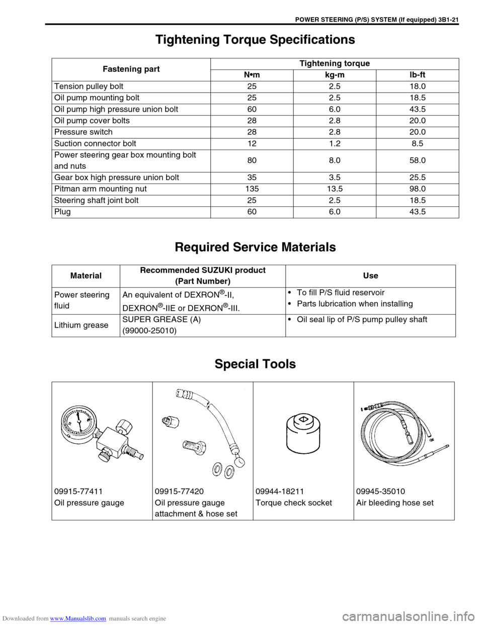
Tightening Torque Specifications
Required Service Materials
Special Tools
Fastening partTightening torque
Nm kg-m lb-ft
Tension pulley bolt 25 2.5 18.0
Oil pump mounting bolt 25 2.5 18.5
Oil pump high pressure union bolt 60 6.0 43.5
Oil pump cover bolts 28 2.8 20.0
Pressure switch 28 2.8 20.0
Suction connector bolt 12 1.2 8.5
Power steering gear box mounting bolt
and nuts80 8.0 58.0
Gear box high pressure union bolt 35 3.5 25.5
Pitman arm mounting nut 135 13.5 98.0
Steering shaft joint bolt 25 2.5 18.5
Plug 60 6.0 43.5
MaterialRecommended SUZUKI product
(Part Number)Use
Power steering
fluidAn equivalent of DEXRON
®-II,
DEXRON
®-IIE or DEXRON®-III.To fill P/S fluid reservoir
Parts lubrication when installing
Lithium greaseSUPER GREASE (A)
(99000-25010)Oil seal lip of P/S pump pulley shaft
09915-77411 09915-77420 09944-18211 09945-35010
Oil pressure gauge Oil pressure gauge
attachment & hose setTorque check socket Air bleeding hose set
Page 187 of 687

Downloaded from www.Manualslib.com manuals search engine 3D-14 FRONT SUSPENSION
Shock Absorber and/or Coil Spring Check
1) Inspect shock absorber for oil leakage. If shock absorber is
found faulty, replace it as an assembly unit, because it can
not be disassembled.
2) Shock absorber function check
Check and adjust tire pressures as specified.
Bounce body three or four times continuously by pushing
front end on the side with shock absorber to be checked.
Apply the same amount of force at each push and note
shock absorber resistance both when pushed and rebound-
ing.
Also, note how many times vehicle body rebounds before
coming to stop after hands are off. Do the same for shock
absorber on the other side.
Compare shock absorber resistance and number of rebound
on the right with those on the left.
And they must be equal in both. With proper shock absorber,
body should come to stop the moment hands are off or after
only one or two small rebounds. If shock absorbers are sus-
pected, compare them with known good vehicle or shock
absorber.
3) Inspect for damage or deformation.
4) Inspect for cracks or deformation in spring seat.
5) Inspect for deterioration of bump stopper.
6) Inspect shock absorber mount for wear, cracks or deforma-
tion.Replace any parts found defective in steps 2) – 6).
Leading Arm / Lateral Rod / Steering Knuckle
Check
Inspect for cracks, deformation or damage.
Page 245 of 687

Downloaded from www.Manualslib.com manuals search engine 3F-2 WHEELS AND TIRES
General Description
Tires
This vehicle is equipped with following tire.
Tire size
: 205/70 R15 or 175/80 R15
The tires are of tubeless type. The tires are designed to operate satisfactorily with loads up to the full rated load
capacity when inflated to the recommended inflation pressure.
Correct tire pressures and driving habits have an important influence on tire life Heavy cornering, excessively
rapid acceleration, and unnecessary sharp braking increase tire wear.
Wheels
Standard equipment wheels are following steel wheels.
15 x 5 1/2 JJ
Replacement Tires
When replacement is necessary, the original equipment type tire should be used. Refer to the Tire Placard.
Replacement tires should be of the same size, load range and construction as those originally on the vehicle.
Use of any other size or type tire may affect ride, handling, speedometer / odometer calibration, vehicle ground
clearance and tire or snow chain clearance to the body and chassis.
It is recommended that new tires be installed in pairs on the same axle. If necessary to replace only one tire, it
should be paired with the tire having the most tread, to equalize braking traction.
The metric term for tire inflation pressure is the kilopascal (kPa).
Tire pressures will usually be printed in both kPa and psi on the
Tire Placard. Metric tire gauges are available from tool suppliers.
The following chart, converts commonly used inflation pressures
from kPa to psi. WARNING:
Do not mix different types of tires on the same vehicle such as radial, bias and bias-belted tires except
in emergencies, because vehicle handling may be seriously affected and may result in loss of control.
kPa
kgf/cm2psi
160
180
200
220
240
260
280
300
320
3401.6
1.8
2.0
2.2
2.4
2.6
2.8
3.0
3.2
3.423
26
29
32
35
38
41
44
47
50