pressure SUZUKI JIMNY 2005 3.G Service Owner's Manual
[x] Cancel search | Manufacturer: SUZUKI, Model Year: 2005, Model line: JIMNY, Model: SUZUKI JIMNY 2005 3.GPages: 687, PDF Size: 13.38 MB
Page 86 of 687

Downloaded from www.Manualslib.com manuals search engine AIR CONDITIONING (OPTIONAL) 1B-25
Charging
Charging procedure
The initial charging of the A/C system is performed from the high
pressure side with the engine stopped.
And next, this method must be followed by charging from the low
pressure side with the engine running.
1) Check to make sure that hoses are routed properly after
evacuating the system. CAUTION:
Always charge through low pressure side of A/C sys-
tem at after the initial charging is performed from the
high pressure side with the engine stopped.
Never charge to high pressure side of A/C system with
engine running.
Do not charge while compressor is hot.
When installing tap valve to refrigerant container to
make a hole there through, carefully follow directions
given by manufacturer.
A pressure gauge should always be used before and
during charging.
The refrigerant container should be emptied of refrig-
erant when discarding it.
The refrigerant container should not be heated up to
40 °C (104 °F) or over.
Refrigerant container should not be reversed in direc-
tion during charging. Reversing in direction causes liq-
uid refrigerant to enter compressor, causing troubles,
such as compression of liquid refrigerant and the like.
NOTE:
The air conditioning system contains HFC-134a (R-134a).
Described here is a method to charge the air conditioning
system with refrigerant from the refrigerant service con-
tainer.
When charging refrigerant recovered by using the refrig-
erant and recycling equipment (when recycling refriger-
ant), follow the procedure described in the equipment
manufacturer’s instruction manual.
Page 87 of 687
Downloaded from www.Manualslib.com manuals search engine 1B-26 AIR CONDITIONING (OPTIONAL)
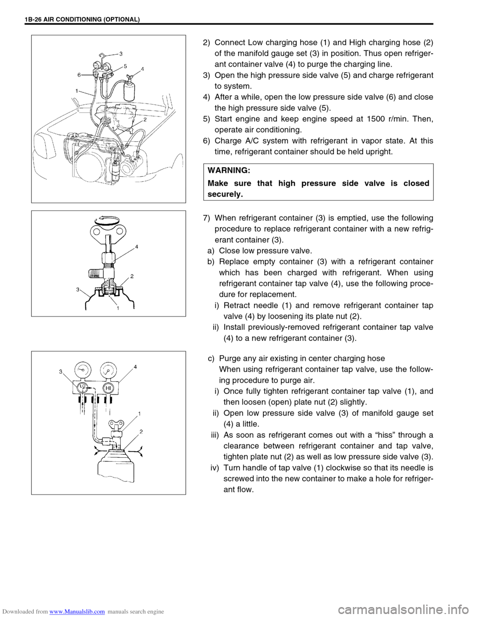
2) Connect Low charging hose (1) and High charging hose (2)
of the manifold gauge set (3) in position. Thus open refriger-
ant container valve (4) to purge the charging line.
3) Open the high pressure side valve (5) and charge refrigerant
to system.
4) After a while, open the low pressure side valve (6) and close
the high pressure side valve (5).
5) Start engine and keep engine speed at 1500 r/min. Then,
operate air conditioning.
6) Charge A/C system with refrigerant in vapor state. At this
time, refrigerant container should be held upright.
7) When refrigerant container (3) is emptied, use the following
procedure to replace refrigerant container with a new refrig-
erant container (3).
a) Close low pressure valve.
b) Replace empty container (3) with a refrigerant container
which has been charged with refrigerant. When using
refrigerant container tap valve (4), use the following proce-
dure for replacement.
i) Retract needle (1) and remove refrigerant container tap
valve (4) by loosening its plate nut (2).
ii) Install previously-removed refrigerant container tap valve
(4) to a new refrigerant container (3).
c) Purge any air existing in center charging hose
When using refrigerant container tap valve, use the follow-
ing procedure to purge air.
i) Once fully tighten refrigerant container tap valve (1), and
then loosen (open) plate nut (2) slightly.
ii) Open low pressure side valve (3) of manifold gauge set
(4) a little.
iii) As soon as refrigerant comes out with a “hiss” through a
clearance between refrigerant container and tap valve,
tighten plate nut (2) as well as low pressure side valve (3).
iv) Turn handle of tap valve (1) clockwise so that its needle is
screwed into the new container to make a hole for refriger-
ant flow. WARNING:
Make sure that high pressure side valve is closed
securely.
Page 88 of 687
Downloaded from www.Manualslib.com manuals search engine AIR CONDITIONING (OPTIONAL) 1B-27
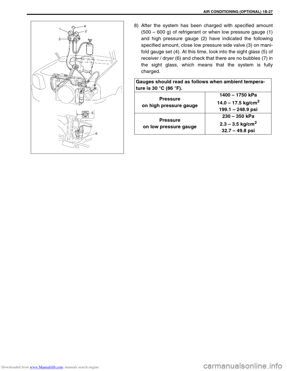
8) After the system has been charged with specified amount
(500 – 600 g) of refrigerant or when low pressure gauge (1)
and high pressure gauge (2) have indicated the following
specified amount, close low pressure side valve (3) on mani-
fold gauge set (4). At this time, look into the sight glass (5) of
receiver / dryer (6) and check that there are no bubbles (7) in
the sight glass, which means that the system is fully
charged.
Gauges should read as follows when ambient tempera-
ture is 30 °C (86 °F).
Pressure
on high pressure gauge1400 – 1750 kPa
14.0 – 17.5 kg/cm
2
199.1 – 248.9 psi
Pressure
on low pressure gauge230 – 350 kPa
2.3 – 3.5 kg/cm
2
32.7 – 49.8 psi
Page 89 of 687
Downloaded from www.Manualslib.com manuals search engine 1B-28 AIR CONDITIONING (OPTIONAL)
Removing Manifold Gauge Set
When A/C system has been charged with a specified amount of
refrigerant, remove manifold gauge set as follows:
1) Close low pressure side valve of manifold gauge set. (The
high pressure side valve is closed continuously during the
process of charging.)
2) Close refrigerant container valve.
3) Stop engine.
4) Using shop rag, remove charging hoses from service valves.
This operation must be performed rapidly.
5) Put caps on service valves.
Leak Test
Whenever a refrigerant leak is suspected in the system or any
service operation has been performed which may result in dis-
turbing lines or connections, it is advisable to test for leaks.
Common sense should be used in performing any refrigerant leak
test, since the need and extent of any such test will, in general,
depend upon the nature of a complaint and the type of a service
performed on the system.
LIQUID LEAK DETECTOR
There are a number of fittings and places throughout the air con-
ditioning system where a liquid leak detector solution may be
used to pinpoint refrigerant leaks.
By merely applying the solution to the area in question with a
swab, such as attached to the cap of a vial, bubbles will form
within seconds if there is a leak.
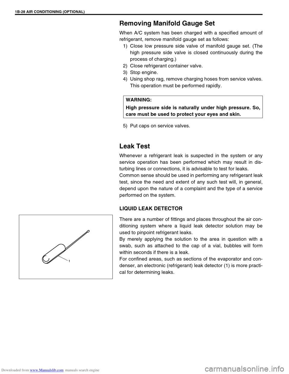
For confined areas, such as sections of the evaporator and con-
denser, an electronic (refrigerant) leak detector (1) is more practi-
cal for determining leaks.WARNING:
High pressure side is naturally under high pressure. So,
care must be used to protect your eyes and skin.
Page 90 of 687
Downloaded from www.Manualslib.com manuals search engine AIR CONDITIONING (OPTIONAL) 1B-29
On-Vehicle Service
Service Precaution
When servicing air conditioning system, note the following instructions.
Refrigerant line
Never use heat for bending pipes. When bending a pipe, try to make its bending radius as slight as possible.
Keep internal parts of air conditioning free from moisture and dirt. When disconnecting any line from system,
install a blind plug or cap to the fitting immediately.
When connecting hoses and pipes, apply a few drops of compressor oil to seats of coupling nuts and O-ring.
When tightening or loosening a fitting, use two wrenches, one for turning and the other for support.
Tighten flared nuts by the following specified torque.
Tightening torque (Flared Nut Used for)
8 mm pipe : 13 N·m (1.3 kg-m, 9.5 lb-ft)
12 mm pipe : 23 N·m (2.3 kg-m, 16.6 lb-ft)
14.5 mm pipe : 33 N·m (3.3 kg-m, 23.8 lb-ft)
Route drain hose so that drained water does not make any contact to vehicle components.
Before evacuating and charging refrigerant, replenish specified amount of compressor oil to compressor
suction side by referring to “Replenishing Compressor Oil” in this section.
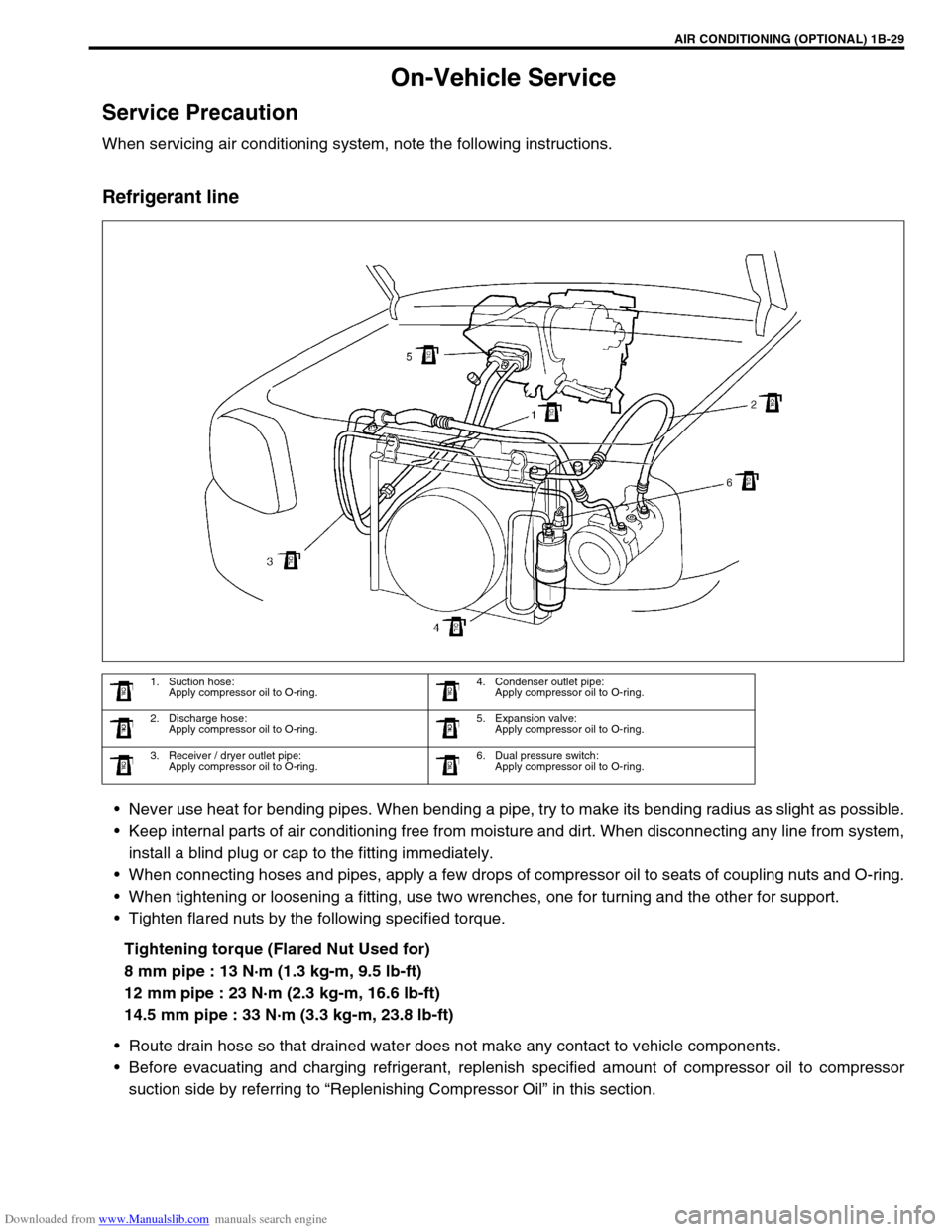
1. Suction hose:
Apply compressor oil to O-ring.4. Condenser outlet pipe:
Apply compressor oil to O-ring.
2. Discharge hose:
Apply compressor oil to O-ring.5. Expansion valve:
Apply compressor oil to O-ring.
3. Receiver / dryer outlet pipe:
Apply compressor oil to O-ring.6. Dual pressure switch:
Apply compressor oil to O-ring.
Page 99 of 687
Downloaded from www.Manualslib.com manuals search engine 1B-38 AIR CONDITIONING (OPTIONAL)
INSTALLATION
Reverse removal procedure for installation, and then note the fol-
lowing instructions.
Replenish specified amount of compressor oil to compressor
suction side by referring to “Replenishing Compressor Oil” in
this section.
Evacuate and charge refrigerant by referring to “Evacuation”
and “Charging” in this section.
Dual Pressure Switch
INSPECTION
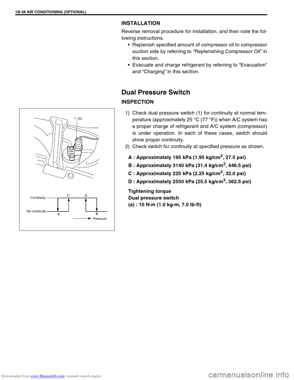
1) Check dual pressure switch (1) for continuity at normal tem-
perature (approximately 25 °C (77 °F)) when A/C system has
a proper charge of refrigerant and A/C system (compressor)
is under operation. In each of these cases, switch should
show proper continuity.
2) Check switch for continuity at specified pressure as shown.
A : Approximately 195 kPa (1.95 kg/cm
2, 27.5 psi)
B : Approximately 3140 kPa (31.4 kg/cm
2, 446.5 psi)
C : Approximately 225 kPa (2.25 kg/cm
2, 32.0 psi)
D : Approximately 2550 kPa (25.5 kg/cm
2, 362.5 psi)
Tightening torque
Dual pressure switch
(a) : 10 N·m (1.0 kg-m, 7.0 lb-ft)
Page 107 of 687
Downloaded from www.Manualslib.com manuals search engine 1B-46 AIR CONDITIONING (OPTIONAL)
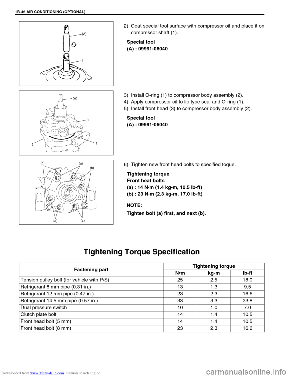
2) Coat special tool surface with compressor oil and place it on
compressor shaft (1).
Special tool
(A) : 09991-06040
3) Install O-ring (1) to compressor body assembly (2).
4) Apply compressor oil to lip type seal and O-ring (1).
5) Install front head (3) to compressor body assembly (2).
Special tool
(A) : 09991-06040
6) Tighten new front head bolts to specified toque.
Tightening torque
Front heat bolts
(a) : 14 N·m (1.4 kg-m, 10.5 lb-ft)
(b) : 23 N·m (2.3 kg-m, 17.0 lb-ft)
Tightening Torque Specification
NOTE:
Tighten bolt (a) first, and next (b).
Fastening partTightening torque
Nm kg-m lb-ft
Tension pulley bolt (for vehicle with P/S) 25 2.5 18.0
Refrigerant 8 mm pipe (0.31 in.) 13 1.3 9.5
Refrigerant 12 mm pipe (0.47 in.) 23 2.3 16.6
Refrigerant 14.5 mm pipe (0.57 in.) 33 3.3 23.8
Dual pressure switch 10 1.0 7.0
Clutch plate bolt 14 1.4 10.5
Front head bolt (5 mm) 14 1.4 10.5
Front head bolt (8 mm) 23 2.3 16.6
Page 111 of 687

Downloaded from www.Manualslib.com manuals search engine 3-2 STEERING, SUSPENSION, WHEELS AND TIRES
General Diagnosis
Since the problems in steering, suspension, wheels and tires involve several systems, they must all be consid-
ered when diagnosing a complaint. To avoid using the wrong symptom, always road test the vehicle first.
Proceed with the following preliminary inspections and correct any defects which are found.
1) Inspect tires for proper pressure and uneven wear.
2) Raise vehicle on a hoist and inspect front and rear suspension and steering system for loose or damaged
parts.
3) Spin front wheel. Inspect for out-of-round tires, out-of-balance tires, bent rims, loose and/or rough wheel
bearings.
Diagnosis Table
Condition Possible Cause Correction
Vehicle Pulls (Leads)
Mismatched or uneven tires Replace tire.
Tires not adequately inflated Adjust tire pressure.
Broken or sagging springs Replace spring.
Radial tire lateral force Replace tire.
Disturbed front wheel alignment Check and adjust wheel alignment.
Disturbed rear wheel alignment Check and adjust wheel alignment.
Brake dragging in one road wheel Repair front brake.
Loose, bent or broken front or rear suspension
partsTighten or replace suspension part.
Abnormal or
Excessive Tire WearSagging or broken springs Replace spring.
Tire out of balance Adjust balance or replace tire.
Disturbed front wheel alignment Check wheel alignment.
Faulty shock absorber Replace shock absorber.
Hard driving Replace tire.
Overloaded vehicle Replace tire.
Not rotating tire Replace or rotate tire.
Worn or loose road wheel bearings Replace wheel bearing.
Wobbly wheel or tires Replace wheel or tire.
Tires not adequately inflated Adjust the pressure.
Wheel Tramp
Blister or bump on tire Replace tire.
Improper shock absorber action Replace shock absorber.
Page 112 of 687

Downloaded from www.Manualslib.com manuals search engine STEERING, SUSPENSION, WHEELS AND TIRES 3-3
Shimmy, Shake or
VibrationTire or wheel out of balance Balance wheels or replace tire
and/or wheel.
Loose wheel bearings Replace wheel bearing.
Loose wheel hub nuts Retighten.
Worn tie rod ends Replace tie rod end.
Worn king pin bearings or king pins Replace king pin bearing and/or
king pin.
Excessive wheel runout Repair or replace wheel and/or tire.
Blister or bump on tire Replace tire.
Excessively loaded radial runout of tire / wheel
assemblyReplace tire or wheel.
Disturbed front wheel alignment Check and adjust front wheel align-
ment.
Loose or worn steering linkage Tighten or replace steering linkage.
Loose steering gear box bolts Tighten box bolts.
Worn steering knuckle oil seal Replace.
Hard Steering
Bind in tie rod end ball studs or king pin bear-
ingsReplace tie rod end or king pin
bearing.
Disturbed front wheel alignment Check and adjust front wheel align-
ment.
Steering gear box adjustment Check and adjust steering gear
box.
Tire not adequately inflated Inflate tires to proper pressure.
Bind in steering column Repair or replace.
Low fluid level, loose drive belt or malfunction of
power steering system (if equipped with P/S)Check and correct.
Too Much Play in
SteeringWheel bearings worn Replace wheel bearing.
Steering gear box attachments loose Tighten or repair.
Steering gear box adjustments Check and adjust steering gear
box.
Worn steering shaft joints Replace joint.
Worn tie rod ends drug rod ball joints Replace tie rod end.
Worn king pin bearings or king pin Replace king pin bearing and/or
king pin.
Poor Returnability
Bind in tie rod end ball studs Replace tie rod end.
Bind in king pin bearings Replace king pin bearing.
Bind in steering column Repair or replace.
Steering gear box needing lubricant Check, repair or lubricate steering
gear box.
Disturbed front wheel alignment Check and adjust front wheel align-
ment.
Steering gear box not properly adjusted Check and adjust steering gear box
torque.
Tires not adequately inflated Adjust pressure.
Steering Noise
(Rattle or Chuckle)Loose bolts and nuts Retighten.
Broken or otherwise damaged wheel bearings Replace wheel bearing.
Worn or sticky tie rod ends Replace tire rod end.
Linkage joints needing grease Lubricate or replace. Condition Possible Cause Correction
Page 113 of 687

Downloaded from www.Manualslib.com manuals search engine 3-4 STEERING, SUSPENSION, WHEELS AND TIRES
Abnormal Noise,
Front EndWorn, sticky or loose tie rod ends, drug rod ball
joints, king pin bearings or axle shaft jointsReplace tie rod end, king pin bear-
ing or axle shaft joint.
Damaged shock absorbers or mountings Replace or repair.
Worn leading arm bushings Replace.
Worn stabilizer bar bushings Replace.
Worn Iateral rod bushings Replace.
Loose stabilizer bar Tighten bolts or replace bushes.
Loose wheel nuts Tighten wheel nuts.
Loose suspension bolts or nuts Tighten suspension bolts or nuts.
Broken or otherwise damaged wheel bearings Replace wheel bearing.
Broken suspension springs Replace spring.
Wander or Poor
Steering StabilityMismatched or uneven tires Replace tire or inflate tires to
proper pressure.
Loose king pin bearings and tie rod ends Replace king pin bearing or tie rod
end.
Faulty shock absorbers or mounting Replace absorber or repair mount-
ing.
Loose stabilizer bar Tighten or replace stabilizer bar or
bushes.
Broken or sagging springs Replace spring.
Steering gear box not properly adjusted Check or adjust steering gear box
torque.
Front wheel alignment Check and adjust front wheel align-
ment.
Erratic Steering when
BrakingWorn wheel bearings Replace wheel bearing.
Broken or sagging springs Replace spring.
Leaking wheel cylinder or caliper Repair or replace wheel cylinder or
caliper.
Warped discs Replace brake disc.
Badly worn brake linings Replace brake shoe lining.
Drum is out of round in some brakes Replace brake drum.
Wheel tires are inflated unequally Inflate tires to proper pressure.
Defective wheel cylinders Replace or repair wheel cylinder.
Disturbed front wheel alignment Check front wheel alignment
Ride Too Soft
Faulty shock absorber Replace shock absorber.
Suspension bottoms
Overloaded Check loading.
Faulty shocks absorber Replace shock absorber.
Incorrect, broken or sagging springs Replace spring.
Body Leans or Sways
in CornersLoose stabilizer bar Tighten stabilizer bar bolts or
replace bushes.
Faulty shocks absorbers or mounting Replace shock absorber or tighten
mounting.
Broken or sagging springs Replace spring.
Overloaded Check loading.
Cupped Tires
Worn wheel bearings Replace wheel bearing.
Excessive tire or wheel run-out Replace tire or wheel disc.
Tire out of balance Adjust tire balance. Condition Possible Cause Correction