Switch SUZUKI JIMNY 2005 3.G Service Repair Manual
[x] Cancel search | Manufacturer: SUZUKI, Model Year: 2005, Model line: JIMNY, Model: SUZUKI JIMNY 2005 3.GPages: 687, PDF Size: 13.38 MB
Page 168 of 687
Downloaded from www.Manualslib.com manuals search engine STEERING WHEEL AND COLUMN 3C-15
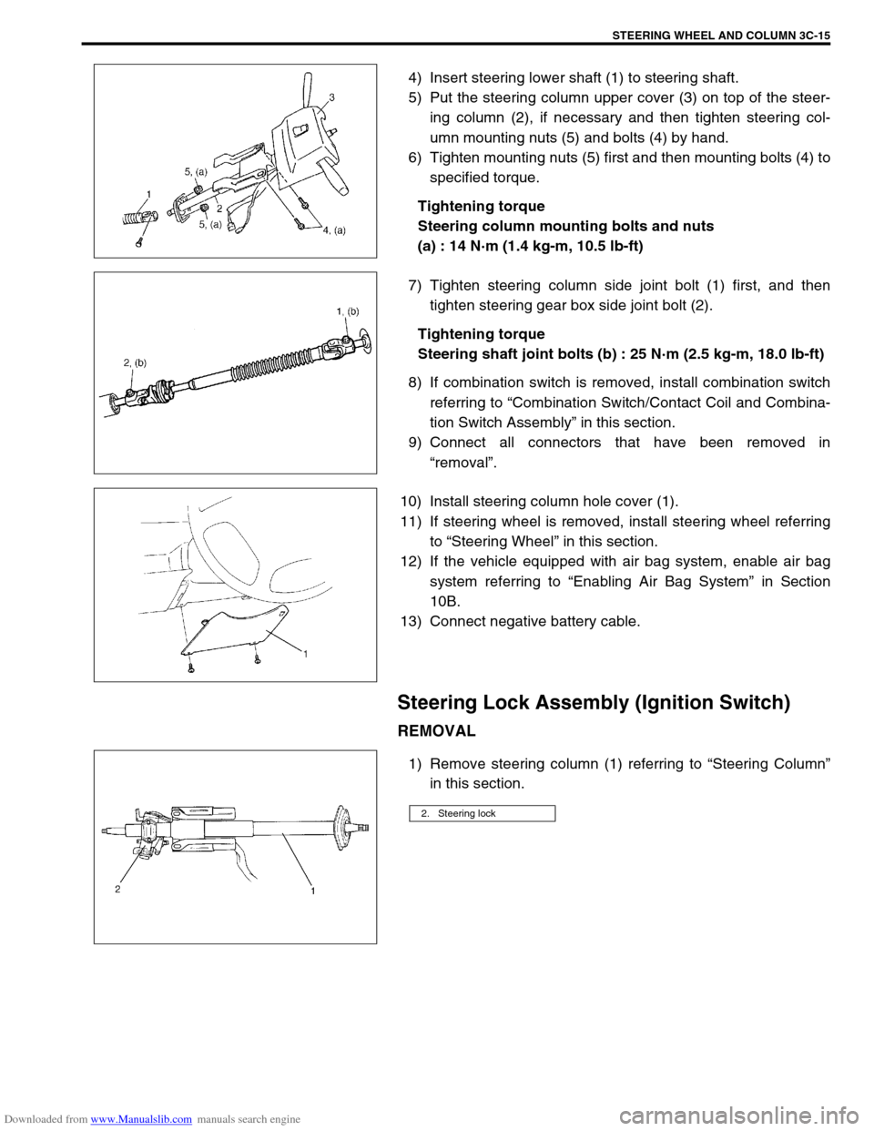
4) Insert steering lower shaft (1) to steering shaft.
5) Put the steering column upper cover (3) on top of the steer-
ing column (2), if necessary and then tighten steering col-
umn mounting nuts (5) and bolts (4) by hand.
6) Tighten mounting nuts (5) first and then mounting bolts (4) to
specified torque.
Tightening torque
Steering column mounting bolts and nuts
(a) : 14 N·m (1.4 kg-m, 10.5 lb-ft)
7) Tighten steering column side joint bolt (1) first, and then
tighten steering gear box side joint bolt (2).
Tightening torque
Steering shaft joint bolts (b) : 25 N·m (2.5 kg-m, 18.0 lb-ft)
8) If combination switch is removed, install combination switch
referring to “Combination Switch/Contact Coil and Combina-
tion Switch Assembly” in this section.
9) Connect all connectors that have been removed in
“removal”.
10) Install steering column hole cover (1).
11) If steering wheel is removed, install steering wheel referring
to “Steering Wheel” in this section.
12) If the vehicle equipped with air bag system, enable air bag
system referring to “Enabling Air Bag System” in Section
10B.
13) Connect negative battery cable.
Steering Lock Assembly (Ignition Switch)
REMOVAL
1) Remove steering column (1) referring to “Steering Column”
in this section.
2. Steering lock
Page 169 of 687
Downloaded from www.Manualslib.com manuals search engine 3C-16 STEERING WHEEL AND COLUMN
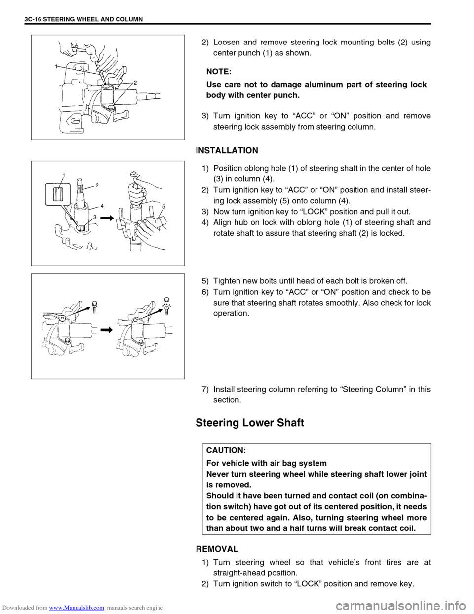
2) Loosen and remove steering lock mounting bolts (2) using
center punch (1) as shown.
3) Turn ignition key to “ACC” or “ON” position and remove
steering lock assembly from steering column.
INSTALLATION
1) Position oblong hole (1) of steering shaft in the center of hole
(3) in column (4).
2) Turn ignition key to “ACC” or “ON” position and install steer-
ing lock assembly (5) onto column (4).
3) Now turn ignition key to “LOCK” position and pull it out.
4) Align hub on lock with oblong hole (1) of steering shaft and
rotate shaft to assure that steering shaft (2) is locked.
5) Tighten new bolts until head of each bolt is broken off.
6) Turn ignition key to “ACC” or “ON” position and check to be
sure that steering shaft rotates smoothly. Also check for lock
operation.
7) Install steering column referring to “Steering Column” in this
section.
Steering Lower Shaft
REMOVAL
1) Turn steering wheel so that vehicle’s front tires are at
straight-ahead position.
2) Turn ignition switch to “LOCK” position and remove key. NOTE:
Use care not to damage aluminum part of steering lock
body with center punch.
CAUTION:
For vehicle with air bag system
Never turn steering wheel while steering shaft lower joint
is removed.
Should it have been turned and contact coil (on combina-
tion switch) have got out of its centered position, it needs
to be centered again. Also, turning steering wheel more
than about two and a half turns will break contact coil.
Page 175 of 687
Downloaded from www.Manualslib.com manuals search engine 3D-2 FRONT SUSPENSION
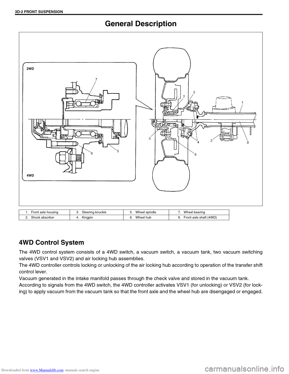
General Description
4WD Control System
The 4WD control system consists of a 4WD switch, a vacuum switch, a vacuum tank, two vacuum switching
valves (VSV1 and VSV2) and air locking hub assemblies.
The 4WD controller controls locking or unlocking of the air locking hub according to operation of the transfer shift
control lever.
Vacuum generated in the intake manifold passes through the check valve and stored in the vacuum tank.
According to signals from the 4WD switch, the 4WD controller activates VSV1 (for unlocking) or VSV2 (for lock-
ing) to apply vacuum from the vacuum tank so that the front axle and the wheel hub are disengaged or engaged.
1. Front axle housing 3. Steering knuckle 5. Wheel spindle 7. Wheel bearing
2. Shock absorber 4. Kingpin 6. Wheel hub 8. Front axle shaft (4WD)
Page 176 of 687
Downloaded from www.Manualslib.com manuals search engine FRONT SUSPENSION 3D-3
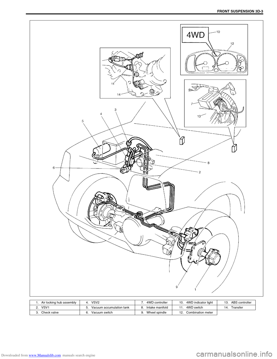
1. Air locking hub assembly 4. VSV2 7. 4WD controller 10. 4WD indicator light 13. ABS controller
2. VSV1 5. Vacuum accumulation tank 8. Intake manifold 11. 4WD switch 14. Transfer
3. Check valve 6. Vacuum switch 9. Wheel spindle 12. Combination meter
Page 177 of 687
Downloaded from www.Manualslib.com manuals search engine 3D-4 FRONT SUSPENSION
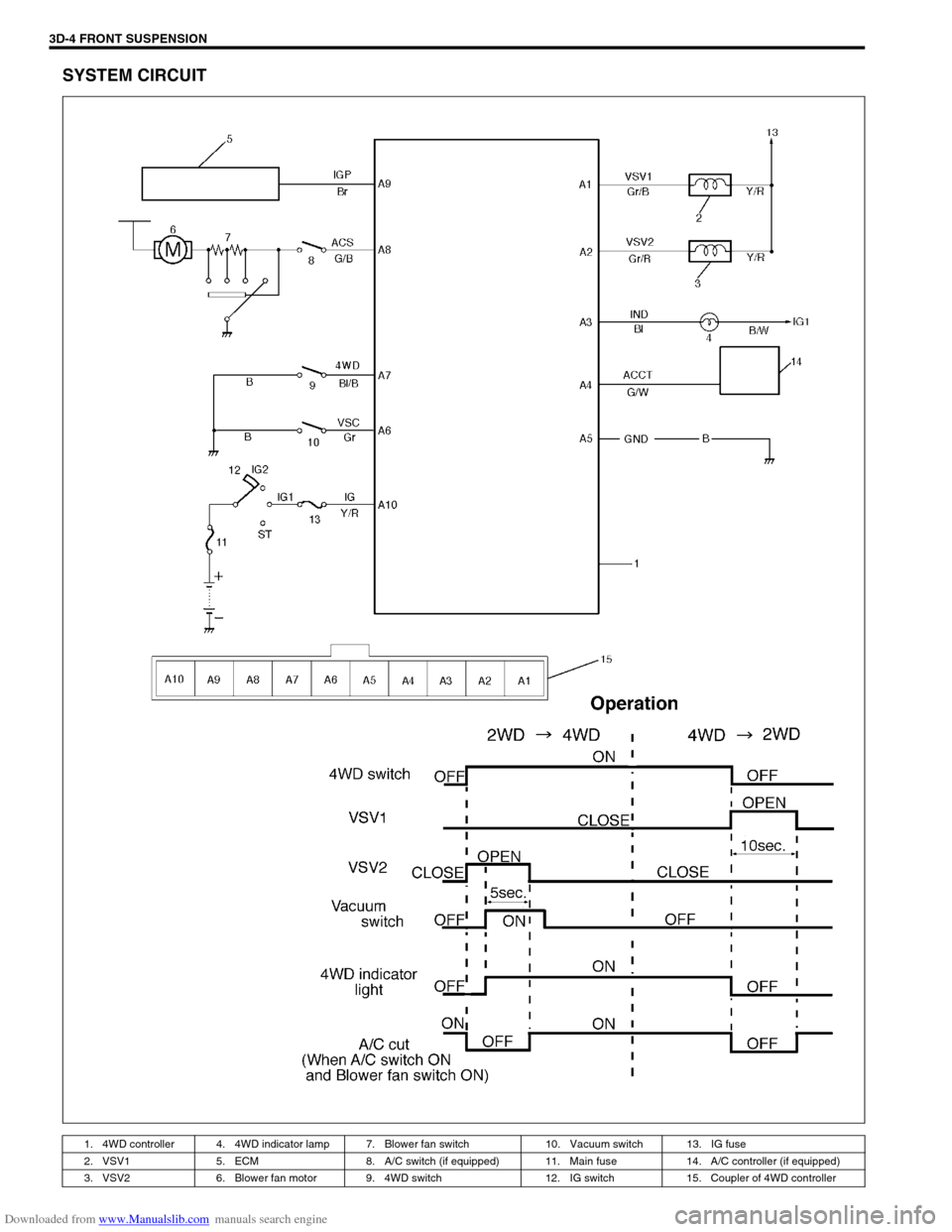
SYSTEM CIRCUIT
1. 4WD controller 4. 4WD indicator lamp 7. Blower fan switch 10. Vacuum switch 13. IG fuse
2. VSV1 5. ECM 8. A/C switch (if equipped) 11. Main fuse 14. A/C controller (if equipped)
3. VSV2 6. Blower fan motor 9. 4WD switch 12. IG switch 15. Coupler of 4WD controller
Page 178 of 687

Downloaded from www.Manualslib.com manuals search engine FRONT SUSPENSION 3D-5
Components and Functions
Component Function
4WD switch When the transfer shift lever is shifted to 4L or 4H position from 2H, this switch
turns ON and cause the 4WD control system to turn ON.
4WD controller When the 4WD switch turns on, the 4WD controller activates VSV2 to lock the
air locking hubs and when it receives an “ON” signal from the vacuum switch, it
makes VSV2 to complete operation within 5 seconds and causes the 4WD indi-
cator light to light up.
If vacuum in the vacuum circuit fails to reach the specified level due to a leakage
in the vacuum circuit (when no “ON” signal is inputted from the vacuum switch),
the 4WD controller stops operation of VSV2 in 15 seconds and makes the 4WD
indicator light to flash to warn occurrence of a trouble.
When the 4WD switch turns off, the 4WD controller activates VSV1 for 10 sec-
onds to unlock the hubs and at the same time makes the 4WD indicator light
turn off.
VSV1 VSV1 operates according to the signal from the 4WD controller. When it is acti-
vated, the port opens and vacuum in the intake manifold is applied through the
vacuum circuit to unlock to the slide gear in the air locking hub. As a result, the
air locking hubs are unlocked.
VSV2 VSV2 operates according to the signal from the 4WD controller. When it is acti-
vated, the port opens and vacuum in the intake manifold is applied through the
vacuum circuit to lock to the slide gear in the air locking hub. As a result, the air
locking hubs are locked.
Vacuum switch When VSV2 receives the “ON” signal from 4WD switch, vacuum is applied
through its circuit to the vacuum switch. The vacuum switch turns on when it
detects vacuum exceeding 260 mmHg.
“4WD” indicator lamp It lights up when 4WD control system is in the 4WD mode.
It flashes to warn that locking hub operation has not completed (4WD control
system fails to shift 4WD).
Page 179 of 687
Downloaded from www.Manualslib.com manuals search engine 3D-6 FRONT SUSPENSION
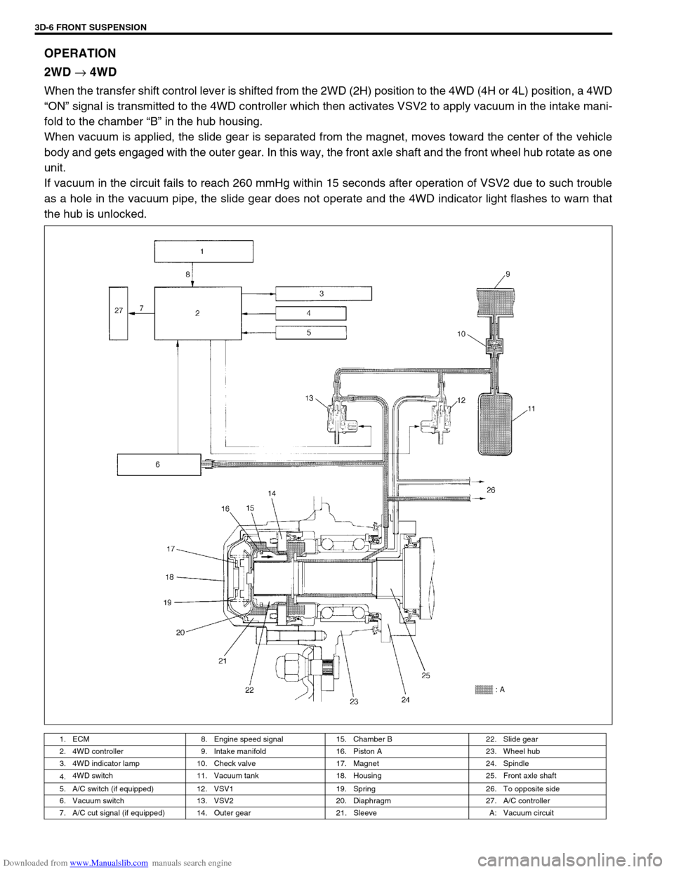
OPERATION
2WD
→ 4WD
When the transfer shift control lever is shifted from the 2WD (2H) position to the 4WD (4H or 4L) position, a 4WD
“ON” signal is transmitted to the 4WD controller which then activates VSV2 to apply vacuum in the intake mani-
fold to the chamber “B” in the hub housing.
When vacuum is applied, the slide gear is separated from the magnet, moves toward the center of the vehicle
body and gets engaged with the outer gear. In this way, the front axle shaft and the front wheel hub rotate as one
unit.
If vacuum in the circuit fails to reach 260 mmHg within 15 seconds after operation of VSV2 due to such trouble
as a hole in the vacuum pipe, the slide gear does not operate and the 4WD indicator light flashes to warn that
the hub is unlocked.
1. ECM 8. Engine speed signal 15. Chamber B 22. Slide gear
2. 4WD controller 9. Intake manifold 16. Piston A 23. Wheel hub
3. 4WD indicator lamp 10. Check valve 17. Magnet 24. Spindle
4.4WD switch 11. Vacuum tank 18. Housing 25. Front axle shaft
5. A/C switch (if equipped) 12. VSV1 19. Spring 26. To opposite side
6. Vacuum switch 13. VSV2 20. Diaphragm 27. A/C controller
7. A/C cut signal (if equipped) 14. Outer gear 21. Sleeve A: Vacuum circuit
Page 180 of 687
Downloaded from www.Manualslib.com manuals search engine FRONT SUSPENSION 3D-7
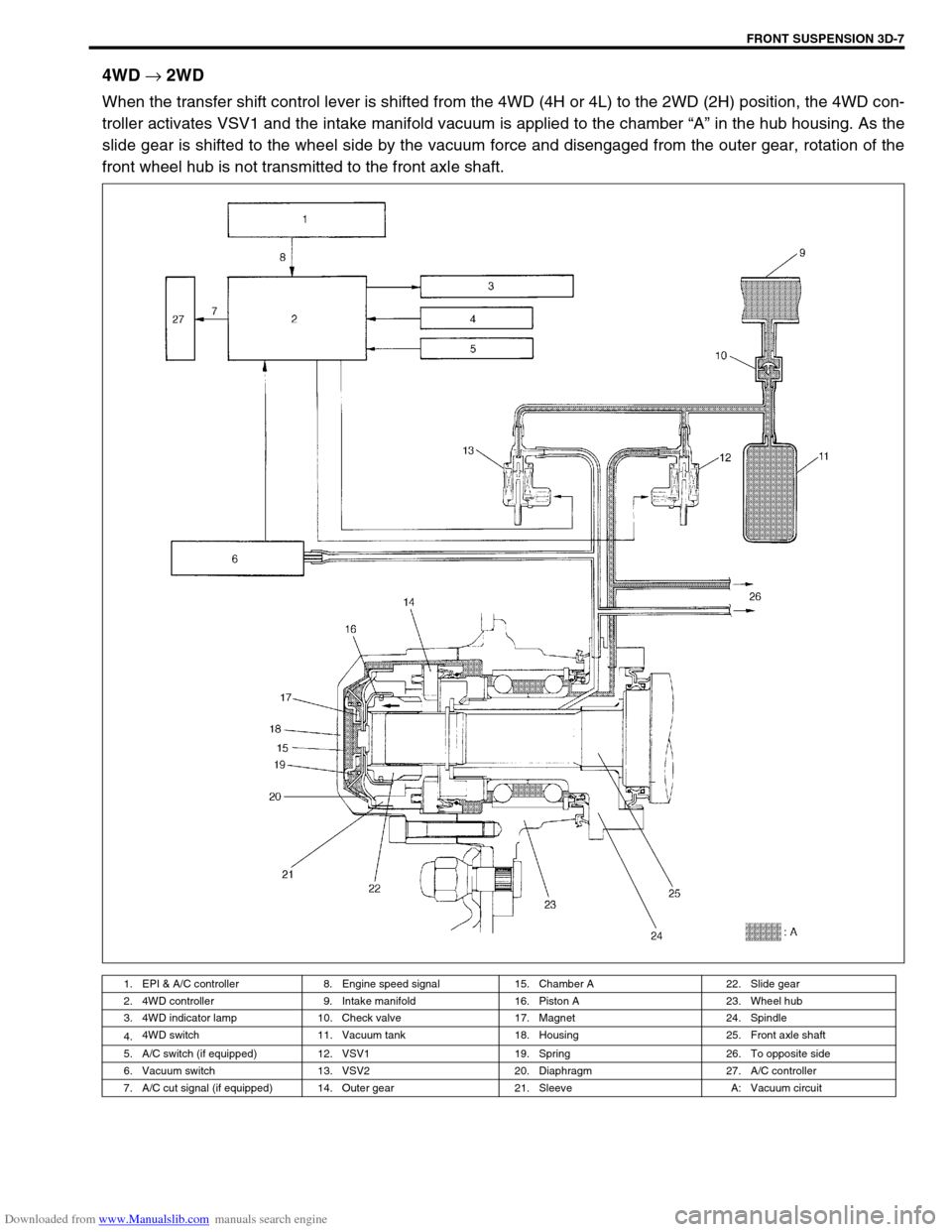
4WD
→ 2WD
When the transfer shift control lever is shifted from the 4WD (4H or 4L) to the 2WD (2H) position, the 4WD con-
troller activates VSV1 and the intake manifold vacuum is applied to the chamber “A” in the hub housing. As the
slide gear is shifted to the wheel side by the vacuum force and disengaged from the outer gear, rotation of the
front wheel hub is not transmitted to the front axle shaft.
1. EPI & A/C controller 8. Engine speed signal 15. Chamber A 22. Slide gear
2. 4WD controller 9. Intake manifold 16. Piston A 23. Wheel hub
3. 4WD indicator lamp 10. Check valve 17. Magnet 24. Spindle
4.4WD switch 11. Vacuum tank 18. Housing 25. Front axle shaft
5. A/C switch (if equipped) 12. VSV1 19. Spring 26. To opposite side
6. Vacuum switch 13. VSV2 20. Diaphragm 27. A/C controller
7. A/C cut signal (if equipped) 14. Outer gear 21. Sleeve A: Vacuum circuit
Page 181 of 687

Downloaded from www.Manualslib.com manuals search engine 3D-8 FRONT SUSPENSION
Diagnosis
Diagnosis Table
For description not found in the table below, refer to “Diagnosis Table” in Section 3.
4WD CONTROL SYSTEM
4WD CONTROL SYSTEM DIAGNOSTIC FLOW TABLE
Before performing the trouble diagnosis, check that the air locking hub assemblies are in good condition and
there is no air leakage from vacuum hoses and vacuum pipe. Refer to “4WD Control System Check” in this sec-
tion for air leakage.
[NOTES ON SYSTEM CIRCUIT INSPECTION]
Be sure to read “Precautions for Electrical Circuit Service” in Section 0A before circuit inspection and
observe what is written there.
For system circuit, refer to the figure of “System Circuit” in this section. Condition Possible Cause Correction
4WD Indicator light
flashingHub locking procedure error
Defective VSV2
Defective vacuum switch
Defective check valve or vacuum tank
Air leak from vacuum circuit
Clogged vacuum hose or pipe
Faulty 4WD controllerShift transfer shift control lever
2WD → 4WD once again
Replace
Replace
Replace
Check and repair
Replace
Check and replace
2WD/4WD switching
errorDefective air locking hub assembly
Abnormality in 4WD control system
Air leakage from vacuum circuit
Clogged vacuum hose or pipe
Defective check valve or vacuum tankReplace
Inspect referring to “4WD Control
System Diagnostic Flow Table”
Check and replace
Replace
Replace
Step Action Yes No
1 Check ground circuit.
1) Disconnect coupler from 4WD controller
with ignition switch OFF.
2) Check for proper connection to 4WD con-
troller at all terminals.
3) If OK, check continuity between A5 terminal
and body ground.
Is there continuity between A5 terminal and
body ground?Go to Step 2.“B” wire is open.
2 Check power circuit.
1) Disconnect coupler from 4WD controller.
2) Turn ignition switch ON.
3) Check voltage between A10 terminal and
ground.
Is it 10 – 14 V?Go to Step 3.“Y/R” circuit is open or
short.
Page 182 of 687

Downloaded from www.Manualslib.com manuals search engine FRONT SUSPENSION 3D-9
3 Check 4WD switch circuit.
1) Connect coupler to 4WD controller.
2) Turn ignition switch ON and check voltage
between A7 terminal and ground.
Transfer lever is in 2H : about 10 – 14 V
Transfer lever is in 4L or 4H : about 0 V
Is check result satisfactory?Go to Step 4. Check 4WD switch (refer
to “4WD Switch” in Sec-
tion 7D), “Bl/B” and “B”
circuits of 4WD switch.
If OK, substitute a known-
good 4WD controller and
recheck.
4 Check VSV1 circuit.
1) Turn ignition switch ON.
2) Check voltage between A1 terminal and
ground.
Is it 10 – 14 V when transfer lever is in 4H or 4L
range and about 0 V for 10 seconds after it is
shifted to 2H range?Go to Step 5. Check VSV1 (refer to
“4WD Control System
Check” in this section),
“Y/R” and “Gr/B” circuits
of VSV1.
If OK, substitute a known-
good 4WD controller and
recheck.
5 Check VSV2 circuit.
1) Turn ignition switch ON.
2) Check voltage between A2 terminal and
ground.
Is it 10 – 14 V when transfer lever is in 2H range
and about 0 V for 5 seconds after it is shifted to
4H or 4L range?Go to Step 6. Check VSV2 (refer to
“4WD Control System
Check” in this section),
“Y/R” and “Gr/R” circuits
of VSV2.
If OK, substitute a known-
good 4WD controller and
recheck.
6 Check vacuum switch circuit.
1) Turn ignition switch ON (stating engine).
2) Check voltage between A6 terminal and
ground.
Is it 10 – 14 V when transfer lever is in 2H range
and about 0 V for 5 seconds after it is shifted to
4H or 4L range?Go to Step 7. Check vacuum switch
(refer to “4WD Control
System Check” in this
section), “Gr” and “B” cir-
cuits of vacuum switch.
If OK, substitute a known-
good 4WD controller and
recheck.
7 Check 4WD indicator light circuit.
1) Turn ignition switch ON.
2) Check voltage between A3 terminal and
ground.
Is it 10 – 14 V when transfer lever is in 2H range
and about 0 V within 15 seconds after it is
shifted to 4H or 4L range?Substitute a known-good
4WD controller and
recheck.Check “Bl” circuit (includ-
ing indicator light and
combination meter refer to
“Combination Meter” in
Section 8).
If OK, substitute a known-
good 4WD controller and
recheck. Step Action Yes No