engine light SUZUKI JIMNY 2005 3.G Service Repair Manual
[x] Cancel search | Manufacturer: SUZUKI, Model Year: 2005, Model line: JIMNY, Model: SUZUKI JIMNY 2005 3.GPages: 687, PDF Size: 13.38 MB
Page 391 of 687

Downloaded from www.Manualslib.com manuals search engine 6-34 ENGINE GENERAL INFORMATION AND DIAGNOSIS
ECM TERMINAL VOLTAGE VALUES TABLE
For TYPE A (See NOTE)
NOTE:
Type A is other than follows.
Type B is left hand steering vehicle equipped with fasten seat belt light and EGR valve or right hand
steering vehicle equipped with fasten seat belt light and immobilizer control system.
TERMINAL
NO.CIRCUIT NORMAL
VOLTAGECONDITION
E191Ground––
2Ground––
3Ground––
4 EVAP canister purge valve 10 – 14 V Ignition switch ON
5Power steering pressure switch
(if equipped)0 – 1.3 VWhile engine running at idle speed, turn
steering wheel to right or left as far as it
stops
10 – 14 V Ignition switch ON
6 Idle air control valve 0 – 13 VAt specified idle speed after engine
warmed up
7 Heater of HO2S-1 10 – 14 V Ignition switch ON
8 Fuel injector NO.4 10 – 14 V Ignition switch ON
9 Fuel injector NO.1 10 – 14 V Ignition switch ON
10 Sensor ground––
11 Camshaft position sensor0 – 0.8 V and
4 – 6 VIgnition switch ON
12–– –
13Heater oxygen sensor-1 Refer to DTC P0130 diag. flow table
CO adjusting resistor (w/o HO2S) 0 – 5 V Ignition switch ON position
14
Engine coolant temp. sensor 0.55 - 0.95 VIgnition switch ON
Engine coolant temp. : 80 °C (176 °F)
15
Intake air temp. sensor 2.0 – 2.7 VIgnition switch ON
Intake air temp. : 20 °C (68 °F)
16 Throttle opening signal0.2 – 1.0 VIgnition switch ON position and throttle
valve at idle position
2.8 – 4.8 VIgnition switch ON position and throttle
valve fully open
17EGR valve (stepper motor coil 3, if
equipped)10 – 14 VIgnition switch ON position leaving engine
OFF
18EGR valve (stepper motor coil 1, if
equipped)10 – 14 VIgnition switch ON position leaving engine
OFF
19 Ignition coil #2––
20 Ignition coil #1––
21 Fuel injector NO.2 10 – 14 V Ignition switch ON
22 Power source for sensors 4.75 – 5.25 V Ignition switch ON
23 Crankshaft position sensor0 – 0.8 or
4 – 5 VIgnition switch ON position
24–– –
25 Knock sensor About 2.5 VAt specified idle speed after engine
warmed up
Page 394 of 687

Downloaded from www.Manualslib.com manuals search engine ENGINE GENERAL INFORMATION AND DIAGNOSIS 6-37
For TYPE B (See NOTE)
E1814Diag. Switch terminal (without
immobilizer indicator lamp)4 – 5 V Ignition switch ON
15Test switch terminal (without immo-
bilizer indicator lamp)4 – 5 V Ignition switch ON
16 A/C (input) signal10 – 14 VIgnition switch ON
A/C switch OFF
0 – 2 VIgnition switch ON
A/C switch ON
17 Lighting switch10 – 14 V Lighting switch ON
0 – 1.3 V Lighting switch OFF
18A/C condenser fan motor relay
(if equipped)0 – 1.0 V A/C is operating
10 – 14 V A/C is not operating
19 Fuel pump relay0 – 1 V For 2 seconds after ignition switch ON
10 – 14 V After the above time
20 Sensor ground––
21Throttle opening signal for
TCM (A/T)Indication
deflection
repeated
0 V and
10 – 14 VIgnition switch ON
22Fuel level sensor (gauge)
(with immobilizer indicator lamp)0 – 2 VIgnition switch ON
Fuel tank fully filled
4.5 – 7.5 VIgnition switch ON
Fuel tank emptied
23–– –
24 Heater blower switch0 – 2.0 VIgnition switch ON and heater blower
switch ON
10 – 14 VIgnition switch ON and heater blower
switch OFF TERMINAL
NO.CIRCUIT NORMAL
VOLTAGECONDITION
NOTE:
See NOTE in “ECM TERMINAL VOLTAGE VALUES TABLE” for applicable model.
TERMINAL
NO.CIRCUIT NORMAL
VOLTAGECONDITION
E181 A/C compressor clutch 0 V Ignition switch ON
2–– –
3–– –
4–– –
5 Power source 10 – 14 V Ignition switch ON
6 Power source 10 – 14 V Ignition switch ON
7 Power source for buck-up 10 – 14 V Ignition switch ON and OFF
8Immobilizer indicator lamp
(with immobilizer indicator lamp)10 – 14 V Engine running
0 – 1.0 V Ignition switch ON leaving engine OFF
Duty output terminal (without
immobilizer indicator lamp)0 – 1.0 V Ignition switch ON
Page 395 of 687

Downloaded from www.Manualslib.com manuals search engine 6-38 ENGINE GENERAL INFORMATION AND DIAGNOSIS
For TYPE A (See NOTE)
E189 Ignition switch 10 – 14 V Ignition switch ON
10 Main relay10 – 14 V Ignition switch OFF
0.4 – 1.5 V Ignition switch ON
11 Ignition switch 10 – 14 V Ignition switch ON
12 Rear defogger switch (if equipped)10 – 14 VIgnition switch ON and rear defogger
switch ON
0 – 1.3 VIgnition switch ON and rear defogger
switch OFF
13–– –
14Diag. Switch terminal (without
immobilizer indicator lamp)4 – 5 V Ignition switch ON
15Test switch terminal (without immo-
bilizer indicator lamp)4 – 5 V Ignition switch ON
16 A/C (input) signal10 – 14 VIgnition switch ON
A/C switch OFF
0 – 2 VIgnition switch ON
A/C switch ON
17 Lighting switch10 – 14 V Lighting switch ON
0 – 1.3 V Lighting switch OFF
18A/C condenser fan motor relay
(if equipped)0 – 1.0 V A/C is operating
10 – 14 V A/C is not operating
19 Fuel pump relay0 – 1 V For 2 seconds after ignition switch ON
10 – 14 V After the above time
20 Engine start signal 6 – 14 V While engine cranking
21 Stop lamp switch0 VIgnition switch ON
Stop lamp switch OFF
10 – 14 VIgnition switch ON
Stop lamp switch ON
22 Vehicle speed sensordeflect
between
0 – 1.6 and
4 – 14 VIgnition switch ON and rear right wheel
turned slowly with rear left wheel locked
23–– –
24–– – TERMINAL
NO.CIRCUIT NORMAL
VOLTAGECONDITION
NOTE:
See NOTE in “ECM TERMINAL VOLTAGE VALUES TABLE” for applicable model.
TERMINAL
NO.CIRCUIT NORMAL
VOLTAGECONDITION
E171–– –
2 R-range signal (A/T)10 – 14 VIgnition switch ON and shift select switch
in R range
0 – 1.3 VIgnition switch ON and shift select switch
in other than R range
3 Blank––
Page 400 of 687
Downloaded from www.Manualslib.com manuals search engine ENGINE GENERAL INFORMATION AND DIAGNOSIS 6-43
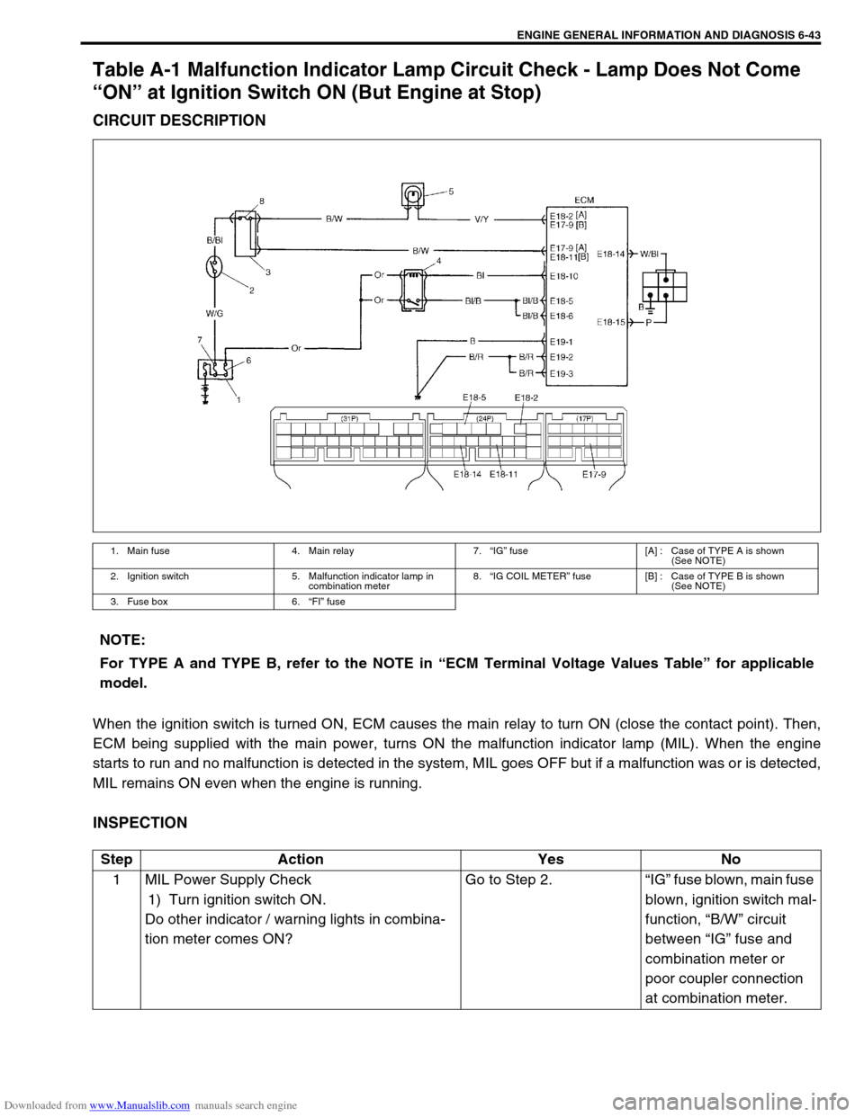
Table A-1 Malfunction Indicator Lamp Circuit Check - Lamp Does Not Come
“ON” at Ignition Switch ON (But Engine at Stop)
CIRCUIT DESCRIPTION
When the ignition switch is turned ON, ECM causes the main relay to turn ON (close the contact point). Then,
ECM being supplied with the main power, turns ON the malfunction indicator lamp (MIL). When the engine
starts to run and no malfunction is detected in the system, MIL goes OFF but if a malfunction was or is detected,
MIL remains ON even when the engine is running.
INSPECTION
1. Main fuse 4. Main relay 7.“IG” fuse [A] : Case of TYPE A is shown
(See NOTE)
2. Ignition switch 5. Malfunction indicator lamp in
combination meter8.“IG COIL METER” fuse [B] : Case of TYPE B is shown
(See NOTE)
3. Fuse box 6.“FI” fuse
NOTE:
For TYPE A and TYPE B, refer to the NOTE in “ECM Terminal Voltage Values Table” for applicable
model.
Step Action Yes No
1 MIL Power Supply Check
1) Turn ignition switch ON.
Do other indicator / warning lights in combina-
tion meter comes ON?Go to Step 2.“IG” fuse blown, main fuse
blown, ignition switch mal-
function, “B/W” circuit
between “IG” fuse and
combination meter or
poor coupler connection
at combination meter.
Page 403 of 687
Downloaded from www.Manualslib.com manuals search engine 6-46 ENGINE GENERAL INFORMATION AND DIAGNOSIS
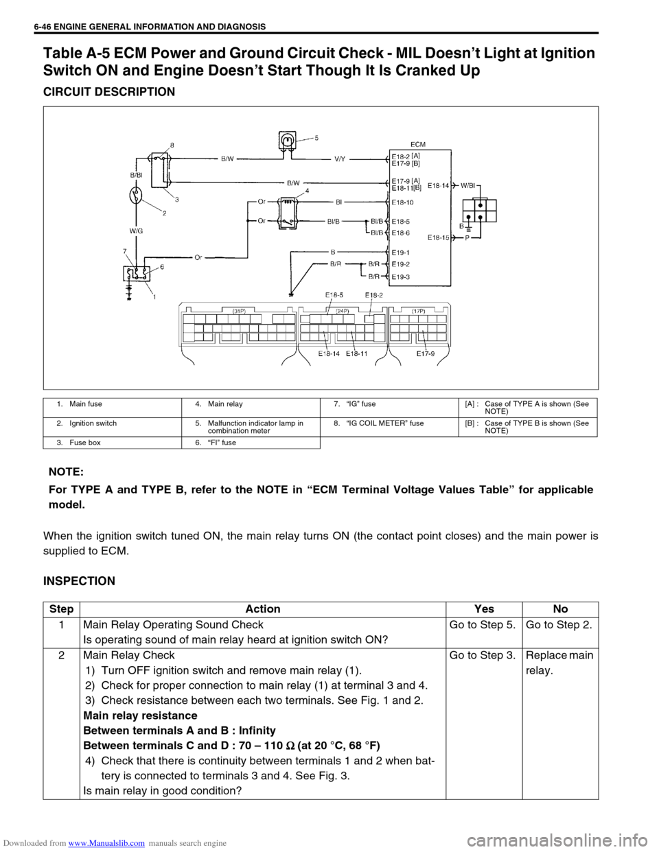
Table A-5 ECM Power and Ground Circuit Check - MIL Doesn’t Light at Ignition
Switch ON and Engine Doesn’t Start Though It Is Cranked Up
CIRCUIT DESCRIPTION
When the ignition switch tuned ON, the main relay turns ON (the contact point closes) and the main power is
supplied to ECM.
INSPECTION
1. Main fuse 4. Main relay 7.“IG” fuse [A] : Case of TYPE A is shown (See
NOTE)
2. Ignition switch 5. Malfunction indicator lamp in
combination meter8.“IG COIL METER” fuse [B] : Case of TYPE B is shown (See
NOTE)
3. Fuse box 6.“FI” fuse
NOTE:
For TYPE A and TYPE B, refer to the NOTE in “ECM Terminal Voltage Values Table” for applicable
model.
Step Action Yes No
1 Main Relay Operating Sound Check
Is operating sound of main relay heard at ignition switch ON?Go to Step 5. Go to Step 2.
2 Main Relay Check
1) Turn OFF ignition switch and remove main relay (1).
2) Check for proper connection to main relay (1) at terminal 3 and 4.
3) Check resistance between each two terminals. See Fig. 1 and 2.
Main relay resistance
Between terminals A and B : Infinity
Between terminals C and D : 70 – 110
Ω
Ω Ω Ω (at 20 °C, 68 °F)
4) Check that there is continuity between terminals 1 and 2 when bat-
tery is connected to terminals 3 and 4. See Fig. 3.
Is main relay in good condition?Go to Step 3. Replace main
relay.
Page 429 of 687
Downloaded from www.Manualslib.com manuals search engine 6-72 ENGINE GENERAL INFORMATION AND DIAGNOSIS
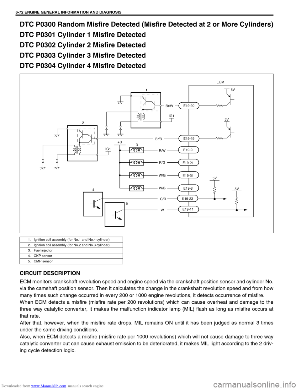
DTC P0300 Random Misfire Detected (Misfire Detected at 2 or More Cylinders)
DTC P0301 Cylinder 1 Misfire Detected
DTC P0302 Cylinder 2 Misfire Detected
DTC P0303 Cylinder 3 Misfire Detected
DTC P0304 Cylinder 4 Misfire Detected
CIRCUIT DESCRIPTION
ECM monitors crankshaft revolution speed and engine speed via the crankshaft position sensor and cylinder No.
via the camshaft position sensor. Then it calculates the change in the crankshaft revolution speed and from how
many times such change occurred in every 200 or 1000 engine revolutions, it detects occurrence of misfire.
When ECM detects a misfire (misfire rate per 200 revolutions) which can cause overheat and damage to the
three way catalytic converter, it makes the malfunction indicator lamp (MIL) flash as long as misfire occurs at
that rate.
After that, however, when the misfire rate drops, MIL remains ON until it has been judged as normal 3 times
under the same driving conditions.
Also, when ECM detects a misfire (misfire rate per 1000 revolutions) which will not cause damage to three way
catalytic converter but can cause exhaust emission to be deteriorated, it makes MIL light according to the 2 driv-
ing cycle detection logic.
1. Ignition coil assembly (for No.1 and No.4 cylinder)
2. Ignition coil assembly (for No.2 and No.3 cylinder)
3. Fuel injector
4. CKP sensor
5. CMP sensor
Page 472 of 687

Downloaded from www.Manualslib.com manuals search engine ENGINE GENERAL INFORMATION AND DIAGNOSIS 6-115
3 Is engine idle speed kept specified speed even
with headlight ON?System is in good condi-
tion.Check IAC system for
operation referring to
Step 3 or Step 4 of DTC
P0505 Diag. Flow Table.
4 Was idle speed higher than specification in Step
1?Go to Step 5. Go to Step 8.
5 Check A/C (input) signal circuit referring to Step 1
of Table B-5 A/C Signal Circuit Check, if
equipped. (A/C signal can be also checked by
using SUZUKI scan tool.)
Is it in good condition?Go to Step 6. Repair or replace A/C
signal circuit or A/C sys-
tem.
6 Check IAC system referring to Step 2 to Step 4 of
DTC P0505 Diag. Flow Table.
Is check result satisfactory?Go to Step 7. Go to Step 5 of DTC
P0505 Diag. Flow Table.
7 Was IAC duty less than about 3% (or more than
about 97% for OFF duty meter) in Step 1 of this
table?Check abnormal air
inhaling from air intake
system, PCV valve and
EVAP canister purge
control system.Check TP sensor
(closed throttle position)
and ECT sensor for per-
formance.
If sensors are OK, sub-
stitute a known-good
ECM.
8 Is SUZUKI scan tool available? Go to Step 9. Go to Step 10.
9 Check PNP signal (“D” range signal).
1) Connect SUZUKI scan tool to DLC with igni-
tion switch OFF.
2) Turn ignition switch ON and check PNP signal
(“P/N” and “D” range) on display when shifting
selector lever to each range. See Table 1.
Is check result satisfactory?Go to Step 11. Repair or replace.
10 Check PNP signal (“D” range signal).
1) Turn ignition switch ON.
2) Check voltage at terminal E17-6 of ECM con-
nector connected. See Fig. 1 and Table 1.
Is check result satisfactory?Go to Step 11. Repair or replace.
11 Check IAC system referring to Step 2 to Step 4 of
DTC P0505 Diag. Flow Table.
Is check result satisfactory?Go to Step 12. Go to Step 5 of DTC
P0505 Diag. Flow Table.
12 Was IAC duty more than about 30% or ✱40% (or
less than 70% or ✱60% for OFF duty meter) in
Step 1 of this table? See NOTE.Check parts or system
which can cause engine
low idle.
Accessory engine load
Clog of air passage
Etc.Substitute a known-good
ECM and recheck. Step Action Yes No
NOTE:
Duty value with (
✱
✱✱ ✱) are applicable to vehicle used at high altitude (higher than 2000 m or 6560 ft).
Page 476 of 687
Downloaded from www.Manualslib.com manuals search engine ENGINE GENERAL INFORMATION AND DIAGNOSIS 6-119
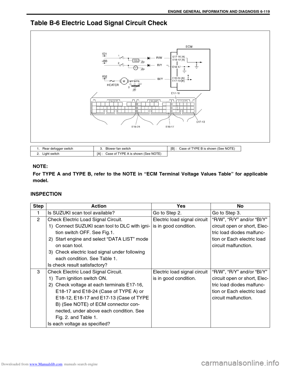
Table B-6 Electric Load Signal Circuit Check
INSPECTION
1. Rear defogger switch 3. Blower fan switch [B] : Case of TYPE B is shown (See NOTE)
2. Light switch [A] : Case of TYPE A is shown (See NOTE)
NOTE:
For TYPE A and TYPE B, refer to the NOTE in “ECM Terminal Voltage Values Table” for applicable
model.
Step Action Yes No
1 Is SUZUKI scan tool available? Go to Step 2. Go to Step 3.
2 Check Electric Load Signal Circuit.
1) Connect SUZUKI scan tool to DLC with igni-
tion switch OFF. See Fig.1.
2) Start engine and select “DATA LIST” mode
on scan tool.
3) Check electric load signal under following
each condition. See Table 1.
Is check result satisfactory?Electric load signal circuit
is in good condition.“R/W”, “R/Y” and/or “Bl/Y”
circuit open or short, Elec-
tric load diodes malfunc-
tion or Each electric load
circuit malfunction.
3 Check Electric Load Signal Circuit.
1) Turn ignition switch ON.
2) Check voltage at each terminals E17-16,
E18-17 and E18-24 (Case of TYPE A) or
E18-12, E18-17 and E17-13 (Case of TYPE
B) (See NOTE) of ECM connector con-
nected, under above each condition. See
Fig. 2. and Table 1.
Is each voltage as specified?Electric load signal circuit
is in good condition.“R/W”, “R/Y” and/or “Bl/Y”
circuit open or short, Elec-
tric load diodes malfunc-
tion or Each electric load
circuit malfunction.
Page 477 of 687
![SUZUKI JIMNY 2005 3.G Service Repair Manual Downloaded from www.Manualslib.com manuals search engine 6-120 ENGINE GENERAL INFORMATION AND DIAGNOSIS
[A] Fig. 1 for Step 2 / [B] Fig. 2 for Step 3
Table 1 for Step 2 and 3
Scan tool or voltmeter
SU SUZUKI JIMNY 2005 3.G Service Repair Manual Downloaded from www.Manualslib.com manuals search engine 6-120 ENGINE GENERAL INFORMATION AND DIAGNOSIS
[A] Fig. 1 for Step 2 / [B] Fig. 2 for Step 3
Table 1 for Step 2 and 3
Scan tool or voltmeter
SU](/img/20/7588/w960_7588-476.png)
Downloaded from www.Manualslib.com manuals search engine 6-120 ENGINE GENERAL INFORMATION AND DIAGNOSIS
[A] Fig. 1 for Step 2 / [B] Fig. 2 for Step 3
Table 1 for Step 2 and 3
Scan tool or voltmeter
SUZUKI
SCAN TOOLVOLTAGE
AT E18-17,
E17-16 or
E18-12VOLTAGE
AT E18-24 or
E17-13
Ignition switch ON, Small
light, heater blower fan and
rear defogger all turnedOFF OFF 0V 10 – 14V
ON ON 10 – 14V 0V
Page 486 of 687
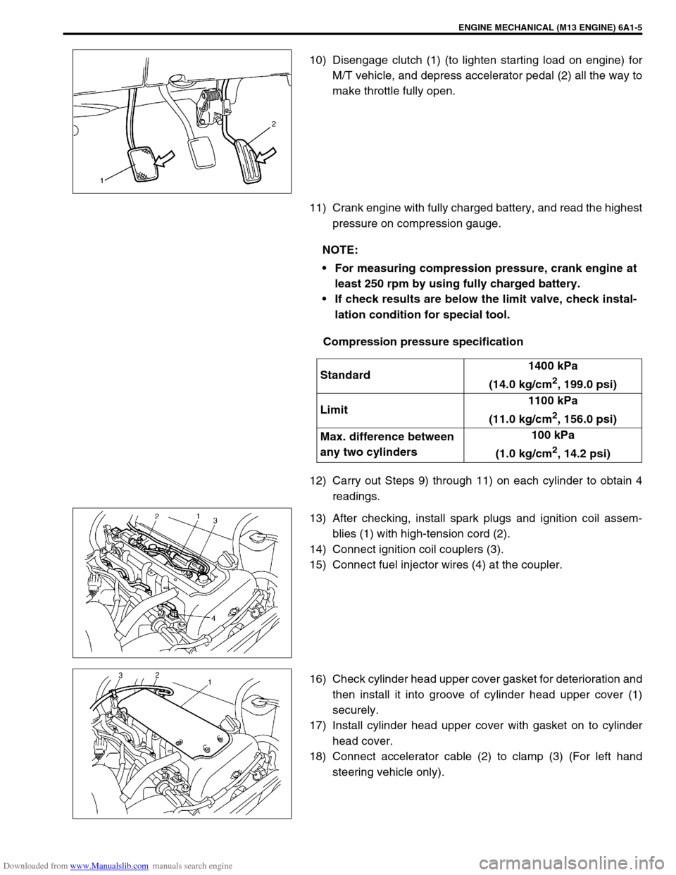
Downloaded from www.Manualslib.com manuals search engine ENGINE MECHANICAL (M13 ENGINE) 6A1-5
10) Disengage clutch (1) (to lighten starting load on engine) for
M/T vehicle, and depress accelerator pedal (2) all the way to
make throttle fully open.
11) Crank engine with fully charged battery, and read the highest
pressure on compression gauge.
Compression pressure specification
12) Carry out Steps 9) through 11) on each cylinder to obtain 4
readings.
13) After checking, install spark plugs and ignition coil assem-
blies (1) with high-tension cord (2).
14) Connect ignition coil couplers (3).
15) Connect fuel injector wires (4) at the coupler.
16) Check cylinder head upper cover gasket for deterioration and
then install it into groove of cylinder head upper cover (1)
securely.
17) Install cylinder head upper cover with gasket on to cylinder
head cover.
18) Connect accelerator cable (2) to clamp (3) (For left hand
steering vehicle only).
NOTE:
For measuring compression pressure, crank engine at
least 250 rpm by using fully charged battery.
If check results are below the limit valve, check instal-
lation condition for special tool.
Standard1400 kPa
(14.0 kg/cm
2, 199.0 psi)
Limit1100 kPa
(11.0 kg/cm
2, 156.0 psi)
Max. difference between
any two cylinders100 kPa
(1.0 kg/cm
2, 14.2 psi)