Connector SUZUKI JIMNY 2005 3.G Service Repair Manual
[x] Cancel search | Manufacturer: SUZUKI, Model Year: 2005, Model line: JIMNY, Model: SUZUKI JIMNY 2005 3.GPages: 687, PDF Size: 13.38 MB
Page 362 of 687

Downloaded from www.Manualslib.com manuals search engine ENGINE GENERAL INFORMATION AND DIAGNOSIS 6-5
Fuel pressure relief procedure
After making sure that engine is cold, release fuel pressure as fol-
lows.
1) Place transmission gear shift lever in “Neutral” (Shift selector
lever to “P” range for A/T model), set parking brake, and
block drive wheels.
2) Remove relay box cover.
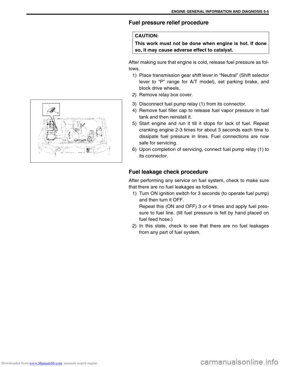
3) Disconnect fuel pump relay (1) from its connector.
4) Remove fuel filler cap to release fuel vapor pressure in fuel
tank and then reinstall it.
5) Start engine and run it till it stops for lack of fuel. Repeat
cranking engine 2-3 times for about 3 seconds each time to
dissipate fuel pressure in lines. Fuel connections are now
safe for servicing.
6) Upon completion of servicing, connect fuel pump relay (1) to
its connector.
Fuel leakage check procedure
After performing any service on fuel system, check to make sure
that there are no fuel leakages as follows.
1) Turn ON ignition switch for 3 seconds (to operate fuel pump)
and then turn it OFF.
Repeat this (ON and OFF) 3 or 4 times and apply fuel pres-
sure to fuel line. (till fuel pressure is felt by hand placed on
fuel feed hose.)
2) In this state, check to see that there are no fuel leakages
from any part of fuel system. CAUTION:
This work must not be done when engine is hot. If done
so, it may cause adverse effect to catalyst.
Page 365 of 687

Downloaded from www.Manualslib.com manuals search engine 6-8 ENGINE GENERAL INFORMATION AND DIAGNOSIS
In the 2nd through the 4th frames, the freeze frame data of each
malfunction is stored in the order as the malfunction is detected.
These data are not updated.
Shown in the table below are examples of how freeze frame data
are stored when two or more malfunctions are detected.
Freeze Frame Data Clearance :
The freeze frame data is cleared at the same time as clearance of
diagnostic trouble code (DTC).
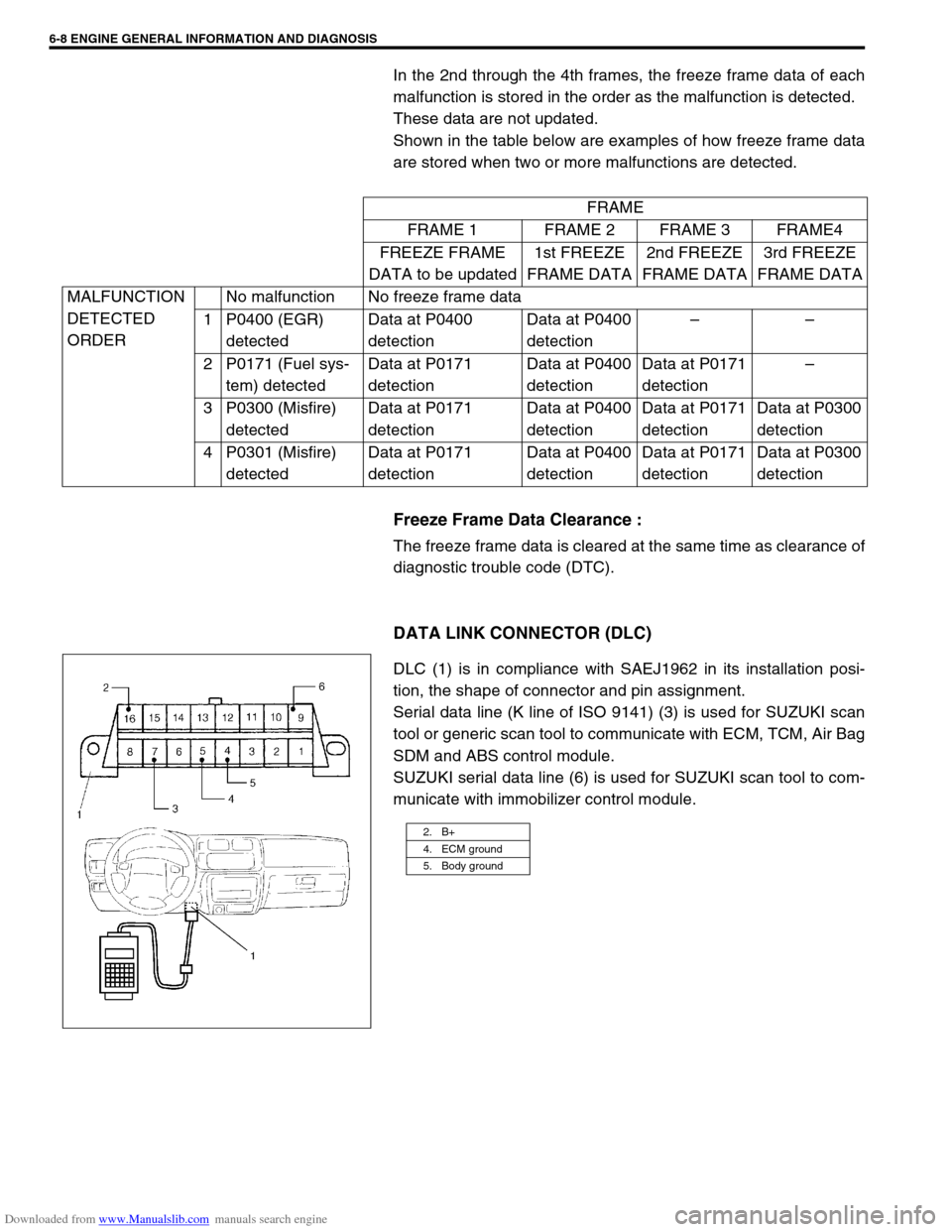
DATA LINK CONNECTOR (DLC)
DLC (1) is in compliance with SAEJ1962 in its installation posi-
tion, the shape of connector and pin assignment.
Serial data line (K line of ISO 9141) (3) is used for SUZUKI scan
tool or generic scan tool to communicate with ECM, TCM, Air Bag
SDM and ABS control module.
SUZUKI serial data line (6) is used for SUZUKI scan tool to com-
municate with immobilizer control module.FRAME
FRAME 1 FRAME 2 FRAME 3 FRAME4
FREEZE FRAME
DATA to be updated1st FREEZE
FRAME DATA2nd FREEZE
FRAME DATA3rd FREEZE
FRAME DATA
MALFUNCTION
DETECTED
ORDERNo malfunction No freeze frame data
1 P0400 (EGR)
detectedData at P0400
detectionData at P0400
detection––
2 P0171 (Fuel sys-
tem) detectedData at P0171
detectionData at P0400
detectionData at P0171
detection–
3 P0300 (Misfire)
detectedData at P0171
detectionData at P0400
detectionData at P0171
detectionData at P0300
detection
4 P0301 (Misfire)
detectedData at P0171
detectionData at P0400
detectionData at P0171
detectionData at P0300
detection
2. B+
4. ECM ground
5. Body ground
Page 366 of 687

Downloaded from www.Manualslib.com manuals search engine ENGINE GENERAL INFORMATION AND DIAGNOSIS 6-9
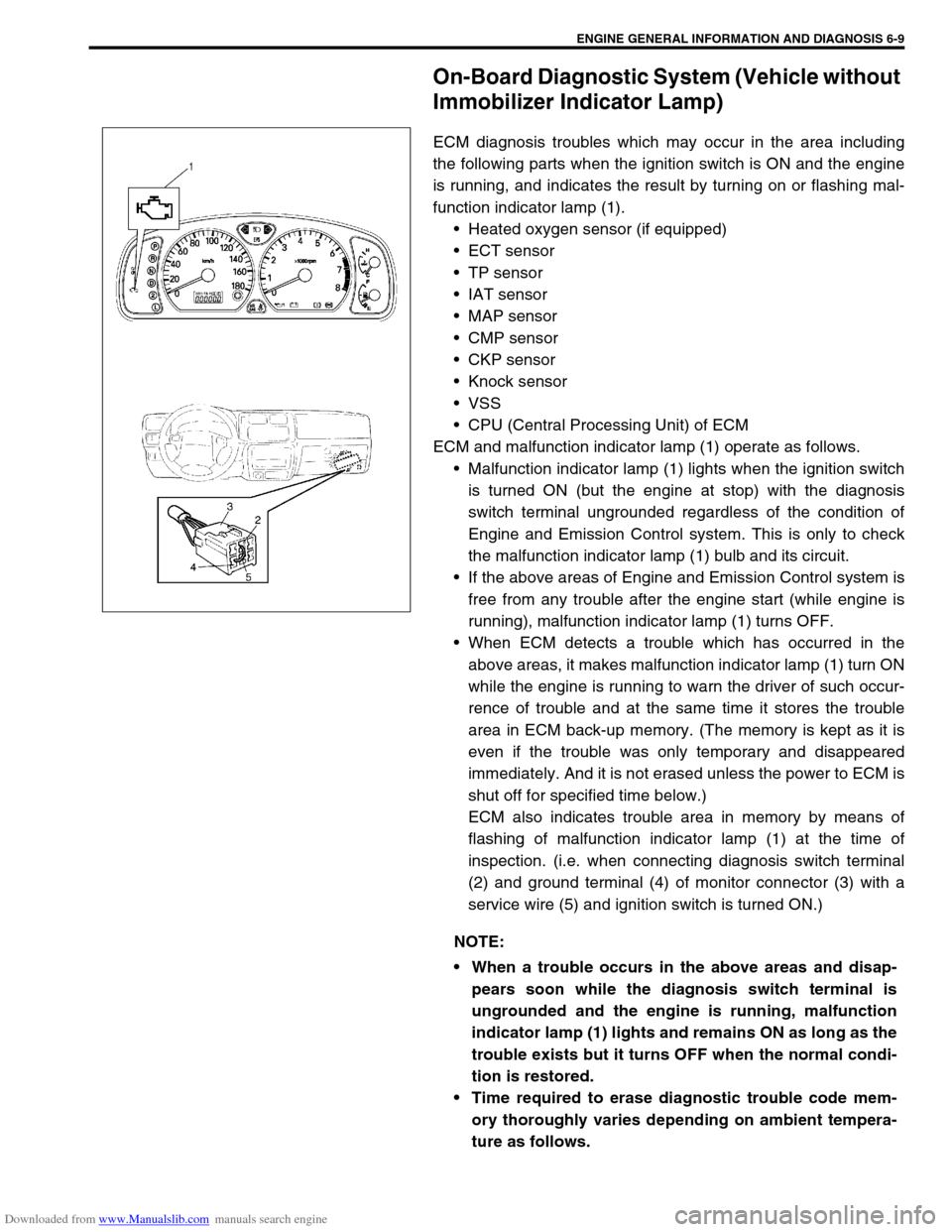
On-Board Diagnostic System (Vehicle without
Immobilizer Indicator Lamp)
ECM diagnosis troubles which may occur in the area including
the following parts when the ignition switch is ON and the engine
is running, and indicates the result by turning on or flashing mal-
function indicator lamp (1).
Heated oxygen sensor (if equipped)
ECT sensor
TP sensor
IAT sensor
MAP sensor
CMP sensor
CKP sensor
Knock sensor
VSS
CPU (Central Processing Unit) of ECM
ECM and malfunction indicator lamp (1) operate as follows.
Malfunction indicator lamp (1) lights when the ignition switch
is turned ON (but the engine at stop) with the diagnosis
switch terminal ungrounded regardless of the condition of
Engine and Emission Control system. This is only to check
the malfunction indicator lamp (1) bulb and its circuit.
If the above areas of Engine and Emission Control system is
free from any trouble after the engine start (while engine is
running), malfunction indicator lamp (1) turns OFF.
When ECM detects a trouble which has occurred in the
above areas, it makes malfunction indicator lamp (1) turn ON
while the engine is running to warn the driver of such occur-
rence of trouble and at the same time it stores the trouble
area in ECM back-up memory. (The memory is kept as it is
even if the trouble was only temporary and disappeared
immediately. And it is not erased unless the power to ECM is
shut off for specified time below.)
ECM also indicates trouble area in memory by means of
flashing of malfunction indicator lamp (1) at the time of
inspection. (i.e. when connecting diagnosis switch terminal
(2) and ground terminal (4) of monitor connector (3) with a
service wire (5) and ignition switch is turned ON.)
NOTE:
When a trouble occurs in the above areas and disap-
pears soon while the diagnosis switch terminal is
ungrounded and the engine is running, malfunction
indicator lamp (1) lights and remains ON as long as the
trouble exists but it turns OFF when the normal condi-
tion is restored.
Time required to erase diagnostic trouble code mem-
ory thoroughly varies depending on ambient tempera-
ture as follows.
Page 369 of 687

Downloaded from www.Manualslib.com manuals search engine 6-12 ENGINE GENERAL INFORMATION AND DIAGNOSIS
1. CUSTOMER COMPLAINT ANALYSIS
Record details of the problem (failure, complaint) and how it occurred as described by the customer. For this
purpose, use of such an inspection form will facilitate collecting information to the point required for proper anal-
ysis and diagnosis.
2. DIAGNOSTIC TROUBLE CODE (DTC) / FREEZE FRAME DATA CHECK, RECORD AND CLEAR-
ANCE
First, check DTC (including pending DTC), referring to “DTC check” section. If DTC is indicated, print it and
freeze frame data or write them down and then clear them by referring to “DTC clearance” section. DTC indi-
cates malfunction that occurred in the system but does not indicate whether it exists now or it occurred in the
past and the normal condition has been restored now. To check which case applies, check the symptom in ques-
tion according to Step 4 and recheck DTC according to Step 5.
Attempt to diagnose a trouble based on DTC in this step only or failure to clear the DTC in this step will lead to
incorrect diagnosis, trouble diagnosis of a normal circuit or difficulty in troubleshooting.
3. AND 4. VISUAL INSPECTION
As a preliminary step, be sure to perform visual check of the items that support proper function of the engine
referring to “Visual Inspection” section.
5. TROUBLE SYMPTOM CONFIRMATION
Based on information obtained in Step 1 Customer complaint analysis and Step 2 DTC / freeze frame data
check, confirm trouble symptoms. Also, reconfirm DTC according to “DTC Confirmation Procedure” described in
each DTC Diagnosis section.
6. AND 7. RECHECKING AND RECORD OF DTC / FREEZE FRAME DATA
Refer to “DTC Check” section for checking procedure.
8. ENGINE BASIC INSPECTION AND ENGINE DIAGNOSIS TABLE
Perform basic engine check according to the “Engine Basic Inspection” first. When the end of the flow table has
been reached, check the parts of the system suspected as a possible cause referring to “Engine Diagnosis
Table” and based on symptoms appearing on the vehicle (symptoms obtained through steps of customer com-
plaint analysis, trouble symptom confirmation and / or basic engine check) and repair or replace faulty parts, if
any.
9. TROUBLESHOOTING FOR DTC (SEE EACH DTC DIAG. FLOW TABLE)
Based on the DTC indicated in Step 5 and referring to the applicable DTC diag. flow table in this section, locate
the cause of the trouble, namely in a sensor, switch, wire harness, connector, actuator, ECM or other part and
repair or replace faulty parts.
10. CHECK FOR INTERMITTENT PROBLEM
Check parts where an intermittent trouble is easy to occur (e.g., wire harness, connector, etc.), referring to
“Intermittent and Poor Connection” in Section 0A and related circuit of DTC recorded in Step 2.
11. FINAL CONFIRMATION TEST
Confirm that the problem symptom has gone and the engine is free from any abnormal conditions. If what has
been repaired is related to the DTC, clear the DTC once, perform DTC confirmation procedure and confirm that
no DTC is indicated.NOTE:
If only Automatic transmission DTCs (P0702-P1717) or Immobilizer DTCs (P1620-P1623) are indicated
in this step, perform trouble diagnosis according to “Diagnosis” in Section 7B or Section 8G.
Page 371 of 687

Downloaded from www.Manualslib.com manuals search engine 6-14 ENGINE GENERAL INFORMATION AND DIAGNOSIS
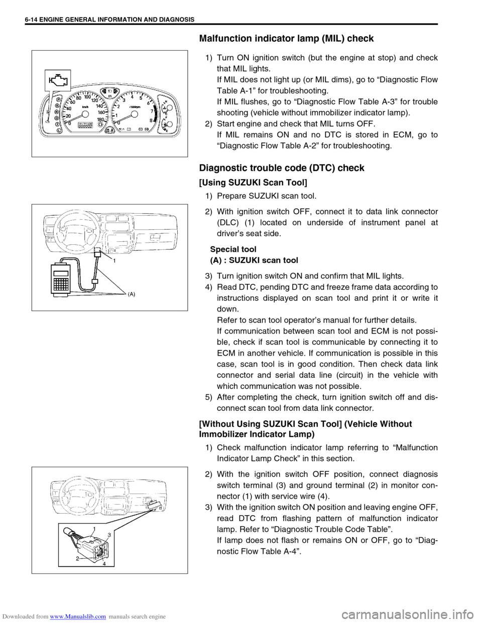
Malfunction indicator lamp (MIL) check
1) Turn ON ignition switch (but the engine at stop) and check
that MIL lights.
If MIL does not light up (or MIL dims), go to “Diagnostic Flow
Table A-1” for troubleshooting.
If MIL flushes, go to “Diagnostic Flow Table A-3” for trouble
shooting (vehicle without immobilizer indicator lamp).
2) Start engine and check that MIL turns OFF.
If MIL remains ON and no DTC is stored in ECM, go to
“Diagnostic Flow Table A-2” for troubleshooting.
Diagnostic trouble code (DTC) check
[Using SUZUKI Scan Tool]
1) Prepare SUZUKI scan tool.
2) With ignition switch OFF, connect it to data link connector
(DLC) (1) located on underside of instrument panel at
driver’s seat side.
Special tool
(A) : SUZUKI scan tool
3) Turn ignition switch ON and confirm that MIL lights.
4) Read DTC, pending DTC and freeze frame data according to
instructions displayed on scan tool and print it or write it
down.
Refer to scan tool operator’s manual for further details.
If communication between scan tool and ECM is not possi-
ble, check if scan tool is communicable by connecting it to
ECM in another vehicle. If communication is possible in this
case, scan tool is in good condition. Then check data link
connector and serial data line (circuit) in the vehicle with
which communication was not possible.
5) After completing the check, turn ignition switch off and dis-
connect scan tool from data link connector.
[Without Using SUZUKI Scan Tool] (Vehicle Without
Immobilizer Indicator Lamp)
1) Check malfunction indicator lamp referring to “Malfunction
Indicator Lamp Check” in this section.
2) With the ignition switch OFF position, connect diagnosis
switch terminal (3) and ground terminal (2) in monitor con-
nector (1) with service wire (4).
3) With the ignition switch ON position and leaving engine OFF,
read DTC from flashing pattern of malfunction indicator
lamp. Refer to “Diagnostic Trouble Code Table”.
If lamp does not flash or remains ON or OFF, go to “Diag-
nostic Flow Table A-4”.
Page 372 of 687

Downloaded from www.Manualslib.com manuals search engine ENGINE GENERAL INFORMATION AND DIAGNOSIS 6-15
4) After completing the check, turn the ignition switch OFF posi-
tion and disconnect service wire from monitor coupler.
Diagnostic trouble code (DTC) clearance
[Using SUZUKI Scan Tool]
1) Connect SUZUKI scan tool to data link connector in the
same manner as when making this connection for DTC
check.
2) Turn ignition switch ON.
3) Erase DTC and pending DTC according to instructions dis-
played on scan tool. Refer to scan tool operator’s manual for
further details.
4) After completing the clearance, turn ignition switch off and
disconnect scan tool from data link connector.
[Without Using SUZUKI Scan Tool]
1) Turn the ignition switch OFF position.
2) Disconnect battery negative cable for specified time below to
erase diagnostic trouble code stored in ECM memory and
reconnect it.
Time required to erase DTC NOTE:
If abnormality or malfunction lies in two or more areas,
malfunction indicator lamp indicates applicable codes
three times each.
And flashing of these codes is repeated as long as
diagnosis terminal is grounded and ignition switch is
held at ON position.
Take a note of diagnostic trouble code indicated first.
NOTE:
DTC and freeze frame data stored in ECM memory are
also cleared in following cases. Be careful not to clear
them before keeping their record.
When power to ECM is cut off (by disconnecting bat-
tery cable, removing fuse or disconnecting ECM con-
nectors)
When the same malfunction (DTC) is not detected
again during 40 engine warm-up cycles.
Ambient temperature Time to cut power to ECM
Over 0 °C (32 °F) 30 sec. or longer
Under 0 °C (32 °F)Not specifiable.
Select a place with higher than
0 °C (32 °F) temperature.
Page 377 of 687

Downloaded from www.Manualslib.com manuals search engine 6-20 ENGINE GENERAL INFORMATION AND DIAGNOSIS
Visual inspection
Visually check following parts and systems.
INSPECTION ITEM REFERRING SECTION
Engine oil – level, leakage Section 0B
Engine coolant – level, leakage Section 0B
Fuel – level, leakage Section 0B
A/T fluid – level, leakage Section 0B
Air cleaner element – dirt, clogging Section 0B
Battery – fluid level, corrosion of terminal
Water pump belt – tension, damage Section 0B
Throttle cable – play, installation
Section 6E Vacuum hoses of air intake system – disconnection, looseness,
deterioration, bend
Connectors of electric wire harness – disconnection, friction
Fuses – burning Section 8
Parts – installation, bolt – looseness
Parts – deformation
Other parts that can be checked visually
Also check following items at engine start, if possible
Malfunction indicator lamp – operation Section 6
Charge warning lamp – operation Section 6H
Engine oil pressure warning lamp – operation Section 8 (Section 6 for pressure check)
Engine coolant temp. meter – operation Section 8
Fuel level meter – operation Section 8
Tachometer, if equipped – operation
Abnormal air being inhaled from air intake system
Exhaust system – leakage of exhaust gas, noise
Other parts that can be checked visually
Page 390 of 687

Downloaded from www.Manualslib.com manuals search engine ENGINE GENERAL INFORMATION AND DIAGNOSIS 6-33
Inspection of ECM and Its Circuits
ECM and its circuits can be checked at ECM wiring connectors by
measuring voltage and resistance.
VOLTAGE CHECK
1) Remove ECM from body referring to Section 6E.
2) Check voltage at each terminal of connectors connected.CAUTION:
ECM cannot be checked by itself. It is strictly prohibited
to connect voltmeter or ohmmeter to ECM with connector
disconnected from it.
NOTE:
As each terminal voltage is affected by the battery volt-
age, confirm that it is 11 V or more when ignition switch
is ON.
1. ECM
2. ECM connectors (Viewed from harness side)
Page 393 of 687

Downloaded from www.Manualslib.com manuals search engine 6-36 ENGINE GENERAL INFORMATION AND DIAGNOSIS
For TYPE A (See NOTE)
E1918EGR valve (stepper motor coil 1, if
equipped)10 – 14 VIgnition switch ON position leaving engine
OFF
19 Ignition coil #2––
20 Ignition coil #1––
21 Fuel injector NO.2 10 – 14 V Ignition switch ON
22 Power source for sensors 4.75 – 5.25 V Ignition switch ON
23 Crankshaft position sensor0 – 0.8 or
4 – 5 VIgnition switch ON position
24–– –
25 Knock sensor About 2.5 VAt specified idle speed after engine
warmed up
26 Manifold absolute pressure sensor 3.3 – 4.0 VIgnition switch ON
Barometric pressure : 100 kPa
(760 mmHg)
27–– –
28EGR valve (stepper motor coil 4, if
equipped)10 – 14 VIgnition switch ON position leaving engine
OFF
29EGR valve (stepper motor coil 2, if
equipped)10 – 14 VIgnition switch ON position leaving engine
OFF
30–– –
31 Fuel injector NO.3 10 – 14 V Ignition switch ON TERMINAL
NO.CIRCUIT NORMAL
VOLTAGECONDITION
NOTE:
See NOTE in “ECM TERMINAL VOLTAGE VALUES TABLE” for applicable model.
TERMINAL
NO.CIRCUIT NORMAL
VOLTAGECONDITION
E181 A/C compressor clutch 0 V Ignition switch ON
2 Malfunction indicator lamp10 – 14 V Engine running
0 – 1.0 V Ignition switch ON leaving engine OFF
3 Data link connector 10 – 14 V Ignition switch ON
4 Heater of HO2S-2 (if equipped) 10 – 14 V Ignition switch ON
5 Power source 10 – 14 V Ignition switch ON
6 Power source 10 – 14 V Ignition switch ON
7 Power source for buck-up 10 – 14 V Ignition switch ON and OFF
8Immobilizer indicator lamp
(with immobilizer indicator lamp)10 – 14 V Engine running
0 – 1.0 V Ignition switch ON leaving engine OFF
Duty output terminal (without
immobilizer indicator lamp)0 – 1.0 V Ignition switch ON
9–– –
10 Main relay10 – 14 V Ignition switch OFF
0.4 – 1.5 V Ignition switch ON
11 Tachometer––
12 Data link connector 4 – 5 V Ignition switch ON
13 Heated oxygen sensor-2 Refer to DTC P0130 diag. flow table
Page 397 of 687

Downloaded from www.Manualslib.com manuals search engine 6-40 ENGINE GENERAL INFORMATION AND DIAGNOSIS
E175 Overdrive cut signal (A/T)0 – 1.0 VIgnition switch ON and ECT less than
60° C
10 – 14 VIgnition switch ON and ECT more than
60 °C
6 D-range idle up signal (A/T)10 – 14 VIgnition switch ON and shift select switch
in other than P and N range
0 – 1.6 VIgnition switch ON and shift select switch
in P and N range
7 Data link connector 4 – 5 V Ignition switch ON
8–– –
9 Malfunction indicator lamp10 – 14 V Engine running
0 – 1.0 V Ignition switch ON leaving engine OFF
10–– –
11 Data link connector 10 – 14 V Ignition switch ON
12 ABS signal (if equipped) 10 – 14 V Ignition switch ON
13 Heater blower switch0 – 2.0 VIgnition switch ON and heater blower
switch ON
10 – 14 VIgnition switch ON and heater blower
switch OFF
14 Sensor ground––
15Throttle opening signal for
TCM (A/T)Indication
deflection
repeated 0 V
and 10 - 14 VIgnition switch ON
16 Tachometer––
17–– – TERMINAL
NO.CIRCUIT NORMAL
VOLTAGECONDITION