boot SUZUKI JIMNY 2005 3.G Service Workshop Manual
[x] Cancel search | Manufacturer: SUZUKI, Model Year: 2005, Model line: JIMNY, Model: SUZUKI JIMNY 2005 3.GPages: 687, PDF Size: 13.38 MB
Page 49 of 687
Downloaded from www.Manualslib.com manuals search engine 0B-18 MAINTENANCE AND LUBRICATION
Steering System
INSPECTION
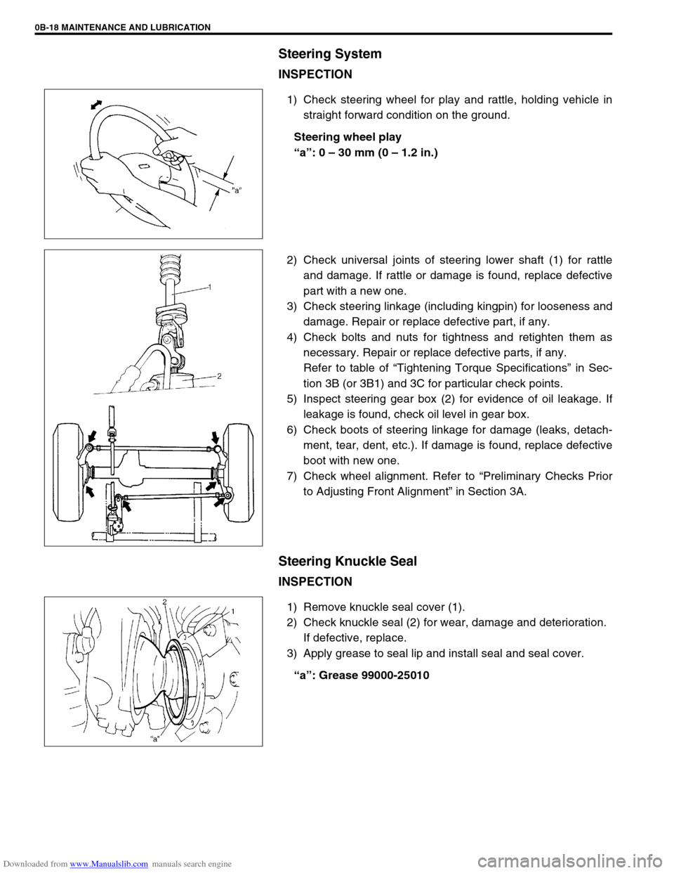
1) Check steering wheel for play and rattle, holding vehicle in
straight forward condition on the ground.
Steering wheel play
“a”: 0 – 30 mm (0 – 1.2 in.)
2) Check universal joints of steering lower shaft (1) for rattle
and damage. If rattle or damage is found, replace defective
part with a new one.
3) Check steering linkage (including kingpin) for looseness and
damage. Repair or replace defective part, if any.
4) Check bolts and nuts for tightness and retighten them as
necessary. Repair or replace defective parts, if any.
Refer to table of “Tightening Torque Specifications” in Sec-
tion 3B (or 3B1) and 3C for particular check points.
5) Inspect steering gear box (2) for evidence of oil leakage. If
leakage is found, check oil level in gear box.
6) Check boots of steering linkage for damage (leaks, detach-
ment, tear, dent, etc.). If damage is found, replace defective
boot with new one.
7) Check wheel alignment. Refer to “Preliminary Checks Prior
to Adjusting Front Alignment” in Section 3A.
Steering Knuckle Seal
INSPECTION
1) Remove knuckle seal cover (1).
2) Check knuckle seal (2) for wear, damage and deterioration.
If defective, replace.
3) Apply grease to seal lip and install seal and seal cover.
“a”: Grease 99000-25010
Page 124 of 687
Downloaded from www.Manualslib.com manuals search engine STEERING GEAR BOX (MANUAL TYPE) AND LINKAGE 3B-3
Diagnosis
Diagnosis Table
Refer to “Diagnosis Table” in Section 3.
Steering Wheel Play Check
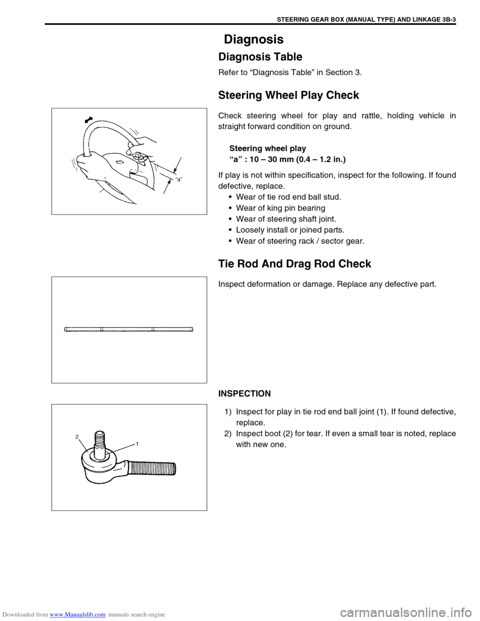
Check steering wheel for play and rattle, holding vehicle in
straight forward condition on ground.
Steering wheel play
“a” : 10 – 30 mm (0.4 – 1.2 in.)
If play is not within specification, inspect for the following. If found
defective, replace.
Wear of tie rod end ball stud.
Wear of king pin bearing
Wear of steering shaft joint.
Loosely install or joined parts.
Wear of steering rack / sector gear.
Tie Rod And Drag Rod Check
Inspect deformation or damage. Replace any defective part.
INSPECTION
1) Inspect for play in tie rod end ball joint (1). If found defective,
replace.
2) Inspect boot (2) for tear. If even a small tear is noted, replace
with new one.
Page 280 of 687
Downloaded from www.Manualslib.com manuals search engine BRAKES 5-19
PIPE
Inspect the tube for damage, cracks, dents and corrosion. If any
defect is found, replace it.
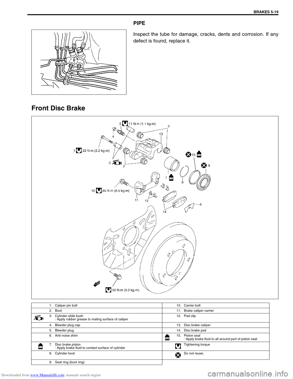
Front Disc Brake
1. Caliper pin bolt 10. Carrier bolt
2. Boot11. Brake caliper carrier
3. Cylinder slide bush
: Apply rubber grease to mating surface of caliper12. Pad clip
4. Bleeder plug cap 13. Disc brake caliper
5. Bleeder plug 14. Disc brake pad
6. Anti noise shim 15. Piston seal
: Apply brake fluid to all around part of piston seal
7. Disc brake piston
: Apply brake fluid to contact surface of cylinderTightening torque
8. Cylinder bootDo not reuse.
9. Seat ring (boot ring)
Page 282 of 687
Downloaded from www.Manualslib.com manuals search engine BRAKES 5-21
INSTALLATION
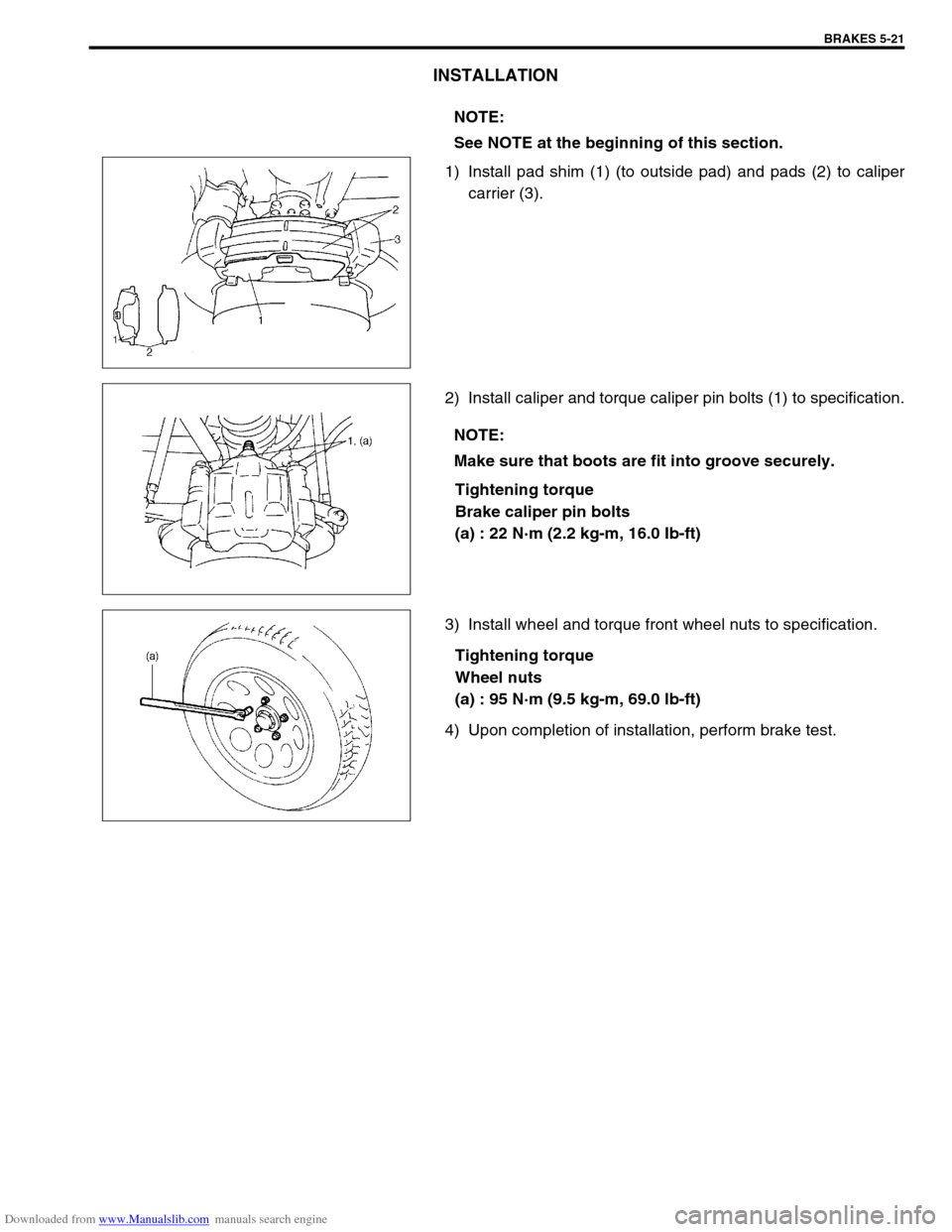
1) Install pad shim (1) (to outside pad) and pads (2) to caliper
carrier (3).
2) Install caliper and torque caliper pin bolts (1) to specification.
Tightening torque
Brake caliper pin bolts
(a) : 22 N·m (2.2 kg-m, 16.0 Ib-ft)
3) Install wheel and torque front wheel nuts to specification.
Tightening torque
Wheel nuts
(a) : 95 N·m (9.5 kg-m, 69.0 lb-ft)
4) Upon completion of installation, perform brake test.NOTE:
See NOTE at the beginning of this section.
NOTE:
Make sure that boots are fit into groove securely.
Page 283 of 687
Downloaded from www.Manualslib.com manuals search engine 5-22 BRAKES
Caliper assembly
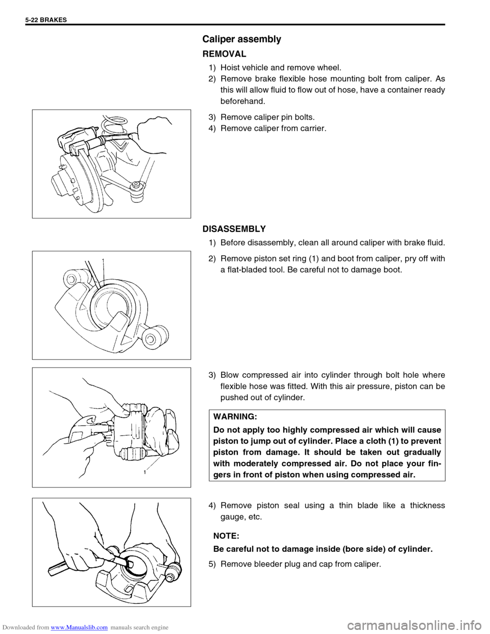
REMOVAL
1) Hoist vehicle and remove wheel.
2) Remove brake flexible hose mounting bolt from caliper. As
this will allow fluid to flow out of hose, have a container ready
beforehand.
3) Remove caliper pin bolts.
4) Remove caliper from carrier.
DISASSEMBLY
1) Before disassembly, clean all around caliper with brake fluid.
2) Remove piston set ring (1) and boot from caliper, pry off with
a flat-bladed tool. Be careful not to damage boot.
3) Blow compressed air into cylinder through bolt hole where
flexible hose was fitted. With this air pressure, piston can be
pushed out of cylinder.
4) Remove piston seal using a thin blade like a thickness
gauge, etc.
5) Remove bleeder plug and cap from caliper.
WARNING:
Do not apply too highly compressed air which will cause
piston to jump out of cylinder. Place a cloth (1) to prevent
piston from damage. It should be taken out gradually
with moderately compressed air. Do not place your fin-
gers in front of piston when using compressed air.
NOTE:
Be careful not to damage inside (bore side) of cylinder.
Page 284 of 687
Downloaded from www.Manualslib.com manuals search engine BRAKES 5-23
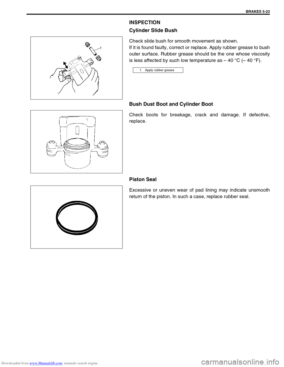
INSPECTION
Cylinder Slide Bush
Check slide bush for smooth movement as shown.
If it is found faulty, correct or replace. Apply rubber grease to bush
outer surface. Rubber grease should be the one whose viscosity
is less affected by such low temperature as – 40 °C (– 40 °F).
Bush Dust Boot and Cylinder Boot
Check boots for breakage, crack and damage. If defective,
replace.
Piston Seal
Excessive or uneven wear of pad lining may indicate unsmooth
return of the piston. In such a case, replace rubber seal.
1. Apply rubber grease
Page 285 of 687
Downloaded from www.Manualslib.com manuals search engine 5-24 BRAKES
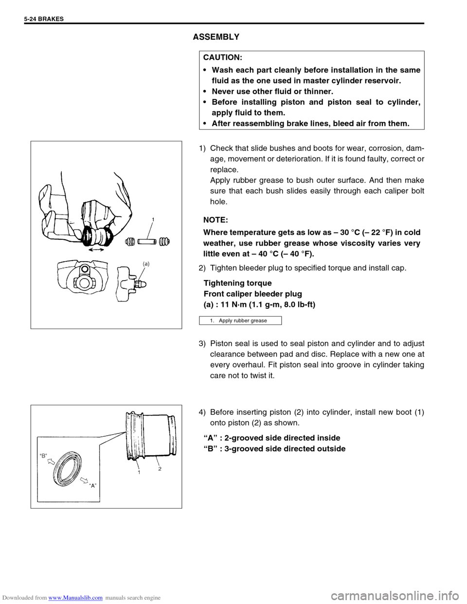
ASSEMBLY
1) Check that slide bushes and boots for wear, corrosion, dam-
age, movement or deterioration. If it is found faulty, correct or
replace.
Apply rubber grease to bush outer surface. And then make
sure that each bush slides easily through each caliper bolt
hole.
2) Tighten bleeder plug to specified torque and install cap.
Tightening torque
Front caliper bleeder plug
(a) : 11 N·m (1.1 g-m, 8.0 lb-ft)
3) Piston seal is used to seal piston and cylinder and to adjust
clearance between pad and disc. Replace with a new one at
every overhaul. Fit piston seal into groove in cylinder taking
care not to twist it.
4) Before inserting piston (2) into cylinder, install new boot (1)
onto piston (2) as shown.
“A” : 2-grooved side directed inside
“B” : 3-grooved side directed outside CAUTION:
Wash each part cleanly before installation in the same
fluid as the one used in master cylinder reservoir.
Never use other fluid or thinner.
Before installing piston and piston seal to cylinder,
apply fluid to them.
After reassembling brake lines, bleed air from them.
NOTE:
Where temperature gets as low as – 30 °C (– 22 °F) in cold
weather, use rubber grease whose viscosity varies very
little even at – 40 °C (– 40 °F).
1. Apply rubber grease
Page 286 of 687
Downloaded from www.Manualslib.com manuals search engine BRAKES 5-25
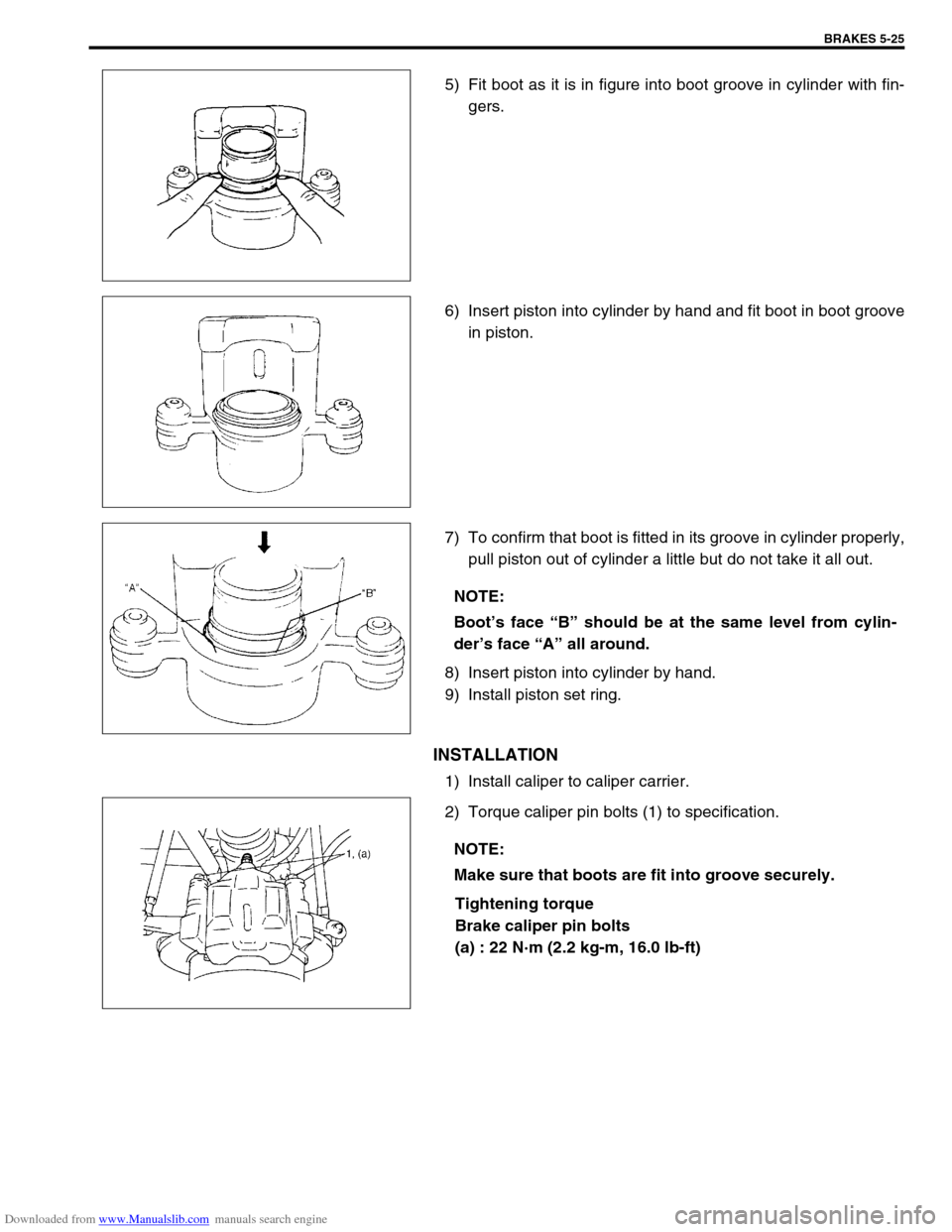
5) Fit boot as it is in figure into boot groove in cylinder with fin-
gers.
6) Insert piston into cylinder by hand and fit boot in boot groove
in piston.
7) To confirm that boot is fitted in its groove in cylinder properly,
pull piston out of cylinder a little but do not take it all out.
8) Insert piston into cylinder by hand.
9) Install piston set ring.
INSTALLATION
1) Install caliper to caliper carrier.
2) Torque caliper pin bolts (1) to specification.
Tightening torque
Brake caliper pin bolts
(a) : 22 N·m (2.2 kg-m, 16.0 lb-ft)
NOTE:
Boot’s face “B” should be at the same level from cylin-
der’s face “A” all around.
NOTE:
Make sure that boots are fit into groove securely.