wheel torque SUZUKI JIMNY 2005 3.G Service Repair Manual
[x] Cancel search | Manufacturer: SUZUKI, Model Year: 2005, Model line: JIMNY, Model: SUZUKI JIMNY 2005 3.GPages: 687, PDF Size: 13.38 MB
Page 314 of 687
Downloaded from www.Manualslib.com manuals search engine BRAKES 5-53
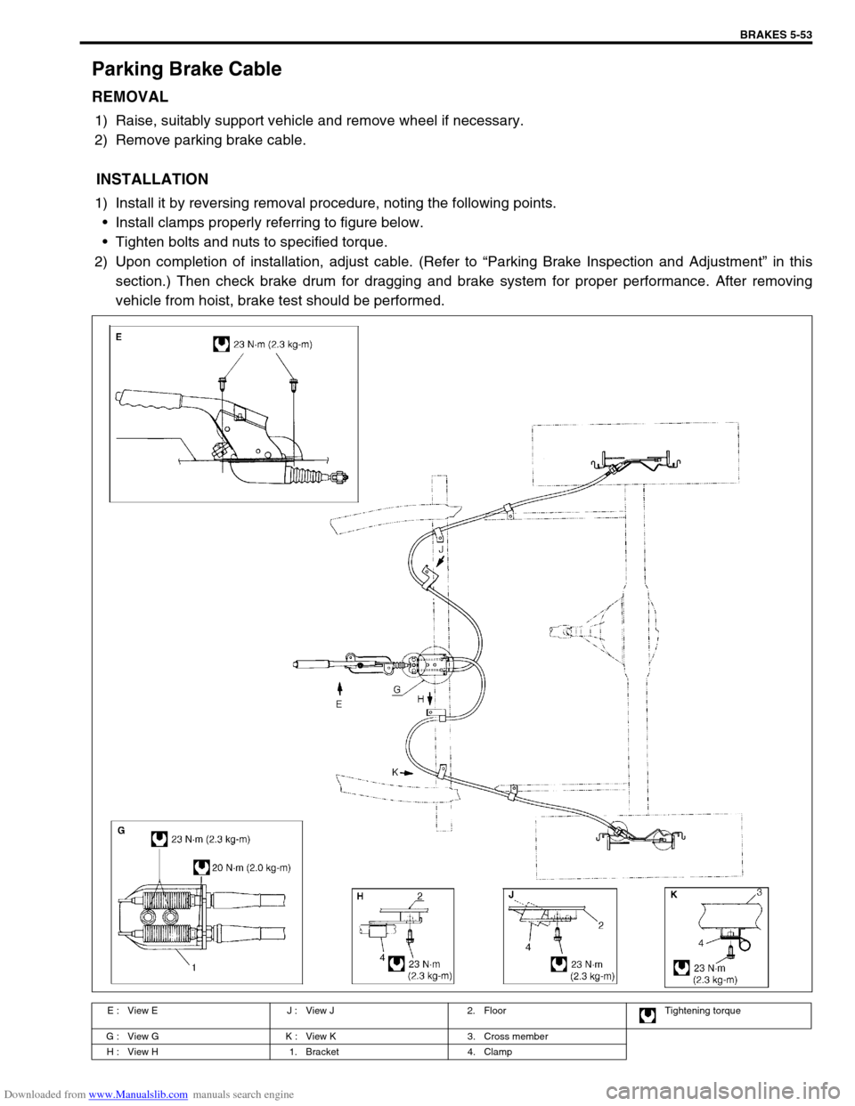
Parking Brake Cable
REMOVAL
1) Raise, suitably support vehicle and remove wheel if necessary.
2) Remove parking brake cable.
INSTALLATION
1) Install it by reversing removal procedure, noting the following points.
Install clamps properly referring to figure below.
Tighten bolts and nuts to specified torque.
2) Upon completion of installation, adjust cable. (Refer to “Parking Brake Inspection and Adjustment” in this
section.) Then check brake drum for dragging and brake system for proper performance. After removing
vehicle from hoist, brake test should be performed.
E : View E J : View J 2. Floor Tightening torque
G : View G K : View K 3. Cross member
H : View H 1. Bracket 4. Clamp
Page 315 of 687

Downloaded from www.Manualslib.com manuals search engine 5-54 BRAKES
Tightening Torque Specifications
Required Service Material
Fastening partTightening torque
Nm kg-m lb-ft
Brake caliper carrier bolt 85 8.5 61.5
Brake caliper pin bolt 22 2.2 16.0
Front brake flexible hose bolt 23 2.3 17.0
Rear brake back plate nut 23 2.3 17.0
Master cylinder nut 13 1.3 9.5
Booster nut 13 1.3 9.5
Brake pipe 5-way 4-way joint bolt 11 1.1 8.0
Brake pipe flare nut 16 1.6 12.0
LSPV bolt/P valve bolt 25 2.5 18.0
Brake bleeder plugFront caliper 11 1.1 8.0
Rear wheel cylinder, LSPV 8 0.8 6.0
Wheel nut 95 9.5 69.0
Hose bracket bolt 11 1.1 8.0
Booster clevis nut 25 2.5 18.0
Stop light switch lock nut 6.5 0.65 4.7
Parking brake lever bolt 23 2.3 17.0
Wheel cylinder mounting bolt 9 0.9 6.5
Piston stopper bolt 10 1.0 7.5
LSPV adjust bolt 25 2.5 18.0
Material Recommended SUZUKI products Use
Brake fluid Indicated on reservoir tank cap or
described in owner’s manual of vehi-
cleTo fill master cylinder reservoir.
To clean and apply to inner parts of master
cylinder caliper and wheel cylinder when they
are disassembled.
Water tight sealant SEALING COMPOUND 366E
99000-31090To apply to mating surfaces of brake back
plate and rear wheel cylinder.
Sealant SUZUKI BOND NO. 1215
99000-31110To apply to mating surfaces of brake back
plate and rear axle housing.
To apply to mating surfaces of brake back
plate and rear wheel bearing retainer.
Page 318 of 687
Downloaded from www.Manualslib.com manuals search engine ANTILOCK BRAKE SYSTEM (ABS) 5E-1
6F1
6F2
6G
6H
6K
7A
7A1
7B1
7C1
7D
7E
7F
8E
5E
9
10
10A
10B
10
10A
10B
SECTION 5E
ANTILOCK BRAKE SYSTEM (ABS)
CONTENTS
General Description ....................................... 5E-2
System Schematic ....................................... 5E-3
ABS Component Parts Location .................. 5E-4
ABS Control Module ..................................... 5E-5
Self-diagnosis function ............................. 5E-5
Fail-safe function ...................................... 5E-5
Diagnosis ........................................................ 5E-6
Precaution in Diagnosing Troubles .............. 5E-6
ABS Diagnostic Flow Table .......................... 5E-6
“ABS” Warning Lamp Check ........................ 5E-9
Diagnostic Trouble Code (DTC) Check ........ 5E-9
DTC Check (Using SUZUKI Scan Tool) ..... 5E-10
Diagnostic Trouble Code (DTC)
Clearance ................................................... 5E-10
Diagnostic Trouble Code (DTC) Table ....... 5E-11
System Circuit ............................................ 5E-12
Table – A “ABS” Warning Lamp Circuit
Check – Lamp Does Not Come “ON”
at Ignition Switch ON .................................. 5E-14
Table – B “ABS” Warning Lamp Circuit
Check – Lamp Comes “ON” Steady ........... 5E-15
Table – C “ABS” Warning Lamp Circuit
Check – Lamp Flashes Continuously
While Ignition Switch is ON ........................ 5E-16
Table – D Code (DTC) is Not Outputted
Even With Diag. Switch Terminal
Connected to Ground. ................................ 5E-17
DTC C1015 (DTC 15) – G Sensor
Circuit ......................................................... 5E-18
DTC C1016 (DTC 16) – Stop Lamp
Circuit ......................................................... 5E-20
DTC C1021 (DTC 21), DTC C1022
(DTC 22) – Right Front Wheel Speed
Sensor Circuit ............................................. 5E-21
DTC C1025 (DTC 25), DTC C1026
(DTC 26) – Left Front Wheel Speed
Sensor Circuit ............................................. 5E-21DTC C1031 (DTC 31), DTC C1032
(DTC 32) – Right Rear Wheel Speed
Sensor Circuit ............................................ 5E-21
DTC C1035 (DTC 35), DTC C1036
(DTC 36) – Left Rear Wheel Speed
Sensor Circuit ............................................ 5E-21
DTC C1041 (DTC 41), DTC C1042
(DTC 42) – Right Front Solenoid Circuit .... 5E-24
DTC C1045 (DTC 45), DTC C1046
(DTC 46) – Left Front Solenoid Circuit....... 5E-24
DTC C1055 (DTC 55), DTC C1056
(DTC 56) – Rear Solenoid Circuit .............. 5E-24
DTC C1057 (DTC 57) – Power Source
Circuit ......................................................... 5E-25
DTC C1061 (DTC 61) – ABS Pump
Motor Circuit............................................... 5E-26
DTC C1063 (DTC 63) – ABS Fail Safe
Circuit ......................................................... 5E-27
DTC C1071 (DTC 71) – ABS Control
Module ....................................................... 5E-28
On-Vehicle Service ...................................... 5E-29
Precaution .................................................. 5E-29
ABS Hydraulic Unit Operation Check ........ 5E-29
ABS Hydraulic Unit / Control Module
Assembly ................................................... 5E-30
Front Wheel Speed Sensor........................ 5E-32
Front Wheel Sensor Ring........................... 5E-35
Rear Wheel Speed Sensor ........................ 5E-36
Rear Wheel Sensor Ring ........................... 5E-38
G Sensor .................................................... 5E-39
Tightening Torque Specification ................ 5E-40
Special Tool .................................................. 5E-40 NOTE:
All brake fasteners are important attaching parts in that they could affect the performance of vital
parts and systems, and/or could result in major repair expense. They must be replaced with one of
same part number or with an equivalent part if replacement part of lesser quality or substitute design.
Torque values must be used as specified during reassembly to assure proper retention of all parts.
There is to be no welding as it may result in extensive damage and weakening of the metal.
Page 339 of 687

Downloaded from www.Manualslib.com manuals search engine 5E-22 ANTILOCK BRAKE SYSTEM (ABS)
INSPECTION
Step Action Yes No
1 1) Disconnect the applicable sensor connector with ignition
switch OFF.
2) Measure resistance between sensor terminals.
Resistance of wheel speed sensor: 1.4 – 1.8 kΩ (at
20°C, 68°F)
3) Measure resistance between each terminal and body
ground.
Insulation resistance: 1MΩ or higher
Were measured resistance values in step 2) and 3) as spec-
ified? (See [A])Go to step 2. Replace sensor.
2 1) Ignition switch OFF.
2) Disconnect connector from ABS hydraulic unit / control
module assembly. (See [B])
3) Check for proper connection to ABS hydraulic unit / con-
trol module assembly at each sensor terminal.
4) If OK, then turn ignition switch ON and measure voltage
between sensor positive terminal of module connector
and body ground.
Is it 0V?Go to step 3. Sensor positive cir-
cuit shorted to
power.
3 1) Ignition switch OFF.
2) Connect connector to sensor.
3) Measure resistance between sensor terminals at mod-
ule connector.
4) Measure resistance between sensor positive terminal
and negative terminal of module connector, between
positive terminal and body ground.
Are measured resistance values within each specified range
described in above step 1?Go to step 4. Circuit open or
shorted to ground.
4 1) Remove wheel speed sensor.
2) Check sensor for damage or foreign material being
attached.
Is it in good condition? (See [C])Go to step 5. Clean or replace
sensor.
5 Check visually through wheel speed sensor installation hole
for following.
Ring serration (teeth) neither missing or damaged.
No foreign material being attached.
Ring not being eccentric.
Wheel bearing free from excessive play.
Are they in good condition? (See [D])Go to step 6. Clean, repair or
replace.
6 1) Install sensor to knuckle or axle housing.
2) Tighten sensor bolt to specified torque and check that
there is not any clearance between sensor and knuckle
or axle housing. (See [E])
Replace sensor if any.
Referring to “Front Wheel Speed Sensor” in this section,
check output voltage or waveform of sensor. Is proper out-
put voltage or waveform obtained?Substitute a known-
good ABS hydraulic
unit / control module
assembly and
recheck.Replace sensor and
recheck.
Page 351 of 687
Downloaded from www.Manualslib.com manuals search engine 5E-34 ANTILOCK BRAKE SYSTEM (ABS)
SENSOR RING INSPECTION
Check ring teeth for being missing, damaged or deformed.
Turn drive shaft and check if ring rotation is free from eccen-
tricity and looseness.
Check that no foreign material is attached.
If any faulty is found, repair or replace.
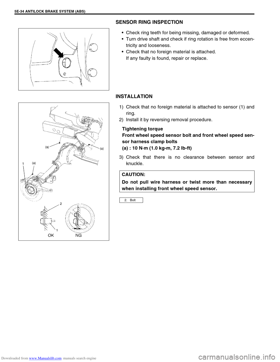
INSTALLATION
1) Check that no foreign material is attached to sensor (1) and
ring.
2) Install it by reversing removal procedure.
Tightening torque
Front wheel speed sensor bolt and front wheel speed sen-
sor harness clamp bolts
(a) : 10 N·m (1.0 kg-m, 7.2 lb-ft)
3) Check that there is no clearance between sensor and
knuckle.
CAUTION:
Do not pull wire harness or twist more than necessary
when installing front wheel speed sensor.
2. Bolt
Page 353 of 687
Downloaded from www.Manualslib.com manuals search engine 5E-36 ANTILOCK BRAKE SYSTEM (ABS)
Rear Wheel Speed Sensor
OUTPUT VOLTAGE INSPECTION
Check in the same procedure as that used of front wheel speed
sensor check.
Output AC voltage at 1 to 1 1/3 rotation per second
: 100 mV or more at 38 – 49 Hz
Reference
When using oscilloscope, peak-to-peak voltage at 1 to
1 1/3 rotation per second
: 280 mV or more at 38 – 49 Hz
REMOVAL
1) Disconnect negative cable from battery.
2) Hoist vehicle.
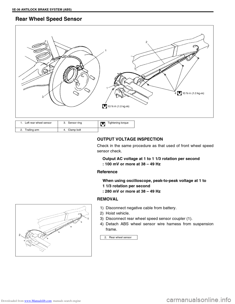
3) Disconnect rear wheel speed sensor coupler (1).
4) Detach ABS wheel sensor wire harness from suspension
frame.
1. Left rear wheel sensor 3. Sensor ring Tightening torque
2. Trailing arm 4. Clamp bolt
2. Rear wheel sensor
Page 354 of 687
Downloaded from www.Manualslib.com manuals search engine ANTILOCK BRAKE SYSTEM (ABS) 5E-37
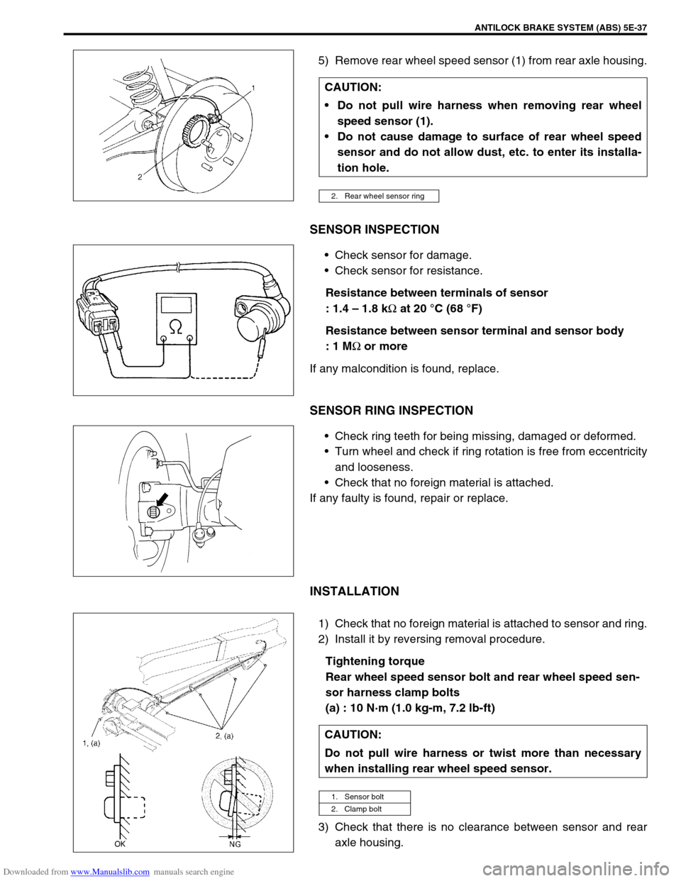
5) Remove rear wheel speed sensor (1) from rear axle housing.
SENSOR INSPECTION
Check sensor for damage.
Check sensor for resistance.
Resistance between terminals of sensor
: 1.4 – 1.8 k
Ω at 20 °C (68 °F)
Resistance between sensor terminal and sensor body
: 1 M
Ω or more
If any malcondition is found, replace.
SENSOR RING INSPECTION
Check ring teeth for being missing, damaged or deformed.
Turn wheel and check if ring rotation is free from eccentricity
and looseness.
Check that no foreign material is attached.
If any faulty is found, repair or replace.
INSTALLATION
1) Check that no foreign material is attached to sensor and ring.
2) Install it by reversing removal procedure.
Tightening torque
Rear wheel speed sensor bolt and rear wheel speed sen-
sor harness clamp bolts
(a) : 10 N·m (1.0 kg-m, 7.2 lb-ft)
3) Check that there is no clearance between sensor and rear
axle housing. CAUTION:
Do not pull wire harness when removing rear wheel
speed sensor (1).
Do not cause damage to surface of rear wheel speed
sensor and do not allow dust, etc. to enter its installa-
tion hole.
2. Rear wheel sensor ring
CAUTION:
Do not pull wire harness or twist more than necessary
when installing rear wheel speed sensor.
1. Sensor bolt
2. Clamp bolt
Page 357 of 687
Downloaded from www.Manualslib.com manuals search engine 5E-40 ANTILOCK BRAKE SYSTEM (ABS)
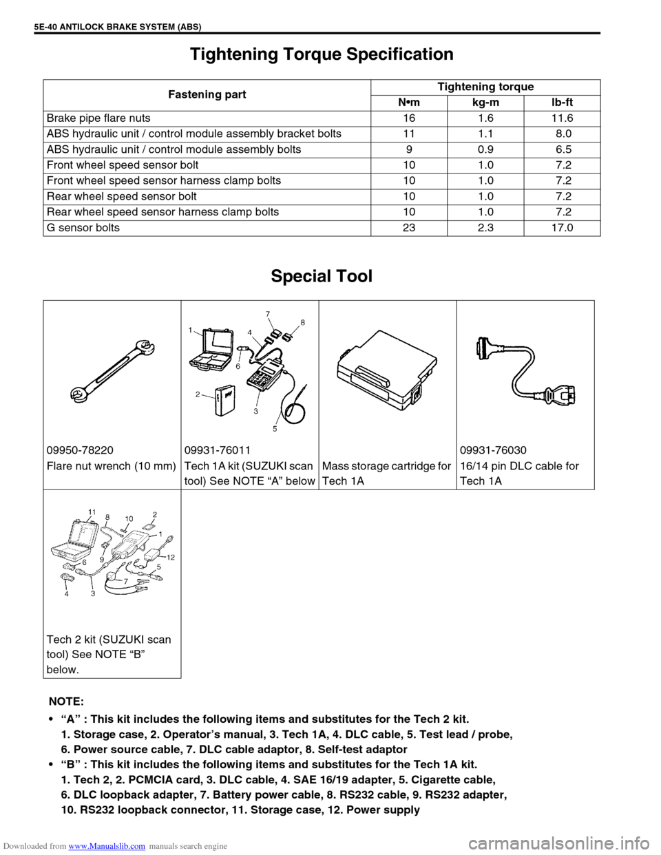
Tightening Torque Specification
Special Tool
Fastening partTightening torque
Nm kg-m lb-ft
Brake pipe flare nuts 16 1.6 11.6
ABS hydraulic unit / control module assembly bracket bolts 11 1.1 8.0
ABS hydraulic unit / control module assembly bolts 9 0.9 6.5
Front wheel speed sensor bolt 10 1.0 7.2
Front wheel speed sensor harness clamp bolts 10 1.0 7.2
Rear wheel speed sensor bolt 10 1.0 7.2
Rear wheel speed sensor harness clamp bolts 10 1.0 7.2
G sensor bolts 23 2.3 17.0
09950-78220 09931-76011 09931-76030
Flare nut wrench (10 mm) Tech 1A kit (SUZUKI scan
tool) See NOTE “A” belowMass storage cartridge for
Tech 1A16/14 pin DLC cable for
Tech 1A
Tech 2 kit (SUZUKI scan
tool) See NOTE “B”
below.
NOTE:
“A” : This kit includes the following items and substitutes for the Tech 2 kit.
1. Storage case, 2. Operator’s manual, 3. Tech 1A, 4. DLC cable, 5. Test lead / probe,
6. Power source cable, 7. DLC cable adaptor, 8. Self-test adaptor
“B” : This kit includes the following items and substitutes for the Tech 1A kit.
1. Tech 2, 2. PCMCIA card, 3. DLC cable, 4. SAE 16/19 adapter, 5. Cigarette cable,
6. DLC loopback adapter, 7. Battery power cable, 8. RS232 cable, 9. RS232 adapter,
10. RS232 loopback connector, 11. Storage case, 12. Power supply
Page 560 of 687
Downloaded from www.Manualslib.com manuals search engine ENGINE MECHANICAL (M13 ENGINE) 6A1-79
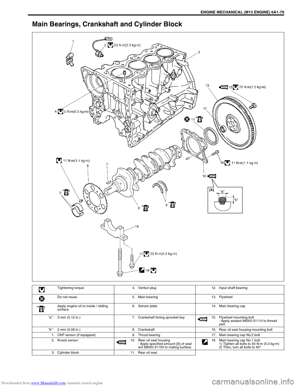
Main Bearings, Crankshaft and Cylinder Block
Tightening torque 4. Venturi plug 12. Input shaft bearing
Do not reuse. 5. Main bearing 13. Flywheel
Apply engine oil to inside / sliding
surface.6. Sensor plate 14. Main bearing cap
“a” : 3 mm (0.12 in.) 7. Crankshaft timing sprocket key 15. Flywheel mounting bolt
: Apply sealant 99000-31110 to thread
part.
“b” : 2 mm (0.08 in.) 8. Crankshaft 16. Rear oil seal housing mounting bolt
1. CKP sensor (if equipped) 9. Thrust bearing 17. Main bearing cap No.2 bolt
2. Knock sensor 10. Rear oil seal housing
: Apply specified amount [A] of seal-
ant 99000-31150 to mating surface. 18. Main bearing cap No.1 bolt
1) Tighten all bolts to 50 N·m (5.0 kg-m)
2) Then, turn all bolts to 60°
3. Cylinder block 11. Rear oil seal
Page 573 of 687
Downloaded from www.Manualslib.com manuals search engine 6A1-92 ENGINE MECHANICAL (M13 ENGINE)
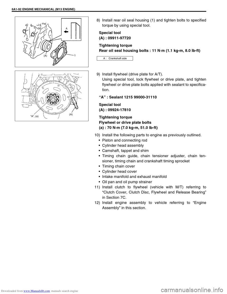
8) Install rear oil seal housing (1) and tighten bolts to specified
torque by using special tool.
Special tool
(A) : 09911-97720
Tightening torque
Rear oil seal housing bolts : 11 N·m (1.1 kg-m, 8.0 lb-ft)
9) Install flywheel (drive plate for A/T).
Using special tool, lock flywheel or drive plate, and tighten
flywheel or drive plate bolts applied with sealant to specifica-
tion.
“A” : Sealant 1215 99000-31110
Special tool
(A) : 09924-17810
Tightening torque
Flywheel or drive plate bolts
(a) : 70 N·m (7.0 kg-m, 51.0 lb-ft)
10) Install the following parts to engine as previously outlined.
Piston and connecting rod
Cylinder head assembly
Camshaft, tappet and shim
Timing chain guide, chain tensioner adjuster, chain ten-
sioner, timing chain and crankshaft timing sprocket
Timing chain cover
Cylinder head cover
Intake manifold and exhaust manifold
Oil pan and oil pump strainer
11) Install clutch to flywheel (vehicle with M/T) referring to
“Clutch Cover, Clutch Disc, Flywheel and Release Bearing”
in Section 7C.
12) Install engine assembly to vehicle referring to “Engine
Assembly” in this section.
A : Crankshaft side