ECO mode SUZUKI JIMNY 2005 3.G Service User Guide
[x] Cancel search | Manufacturer: SUZUKI, Model Year: 2005, Model line: JIMNY, Model: SUZUKI JIMNY 2005 3.GPages: 687, PDF Size: 13.38 MB
Page 396 of 687

Downloaded from www.Manualslib.com manuals search engine ENGINE GENERAL INFORMATION AND DIAGNOSIS 6-39
For TYPE B (See NOTE)
E174Blank––
5 Overdrive cut signal (A/T)0 – 1.0 VIgnition switch ON and ECT less than
60 °C
10 – 14 VIgnition switch ON and ECT more than
60 °C
6 D-range idle up signal (A/T)10 – 14 VIgnition switch ON and shift select switch
in other than P and N range
0 – 1.6 VIgnition switch ON and shift select switch
in P and N range
7 Stop lamp switch0 VIgnition switch ON
Stop lamp switch OFF
10 – 14 VIgnition switch ON
Stop lamp switch ON
8–– –
9 Ignition switch 10 – 14 V Ignition switch ON
10–– –
11 Vehicle speed sensordeflect
between
0 – 1.6 and
4 – 14 VIgnition switch ON and rear right wheel
turned slowly with rear left wheel locked
12 ABS signal (if equipped) 10 – 14 V Ignition switch ON
13 Engine start signal 6 – 14 V While engine cranking
14–– –
15–– –
16 Rear defogger switch (if equipped)10 – 14 V Ignition switch ON and rear defogger
switch ON
0 – 1.3 V Ignition switch ON and rear defogger
switch OFF
17 A/T failure signal (with immobilizer
indicator lamp) (A/T)–– TERMINAL
NO.CIRCUIT NORMAL
VOLTAGECONDITION
NOTE:
See NOTE in “ECM TERMINAL VOLTAGE VALUES TABLE” for applicable model.
TERMINAL
NO.CIRCUIT NORMAL
VOLTAGECONDITION
E171 A/C evaporator temp. sensor 2.0 – 2.3 VIgnition switch ON
A/C evaporator temp. sensor at 25 °C
(77 °F)
2 R-range signal (A/T)10 – 14 VIgnition switch ON and shift select switch
in R range
0 – 1.3 VIgnition switch ON and shift select switch
in other than R range
3Blank––
4Blank––
Page 430 of 687

Downloaded from www.Manualslib.com manuals search engine ENGINE GENERAL INFORMATION AND DIAGNOSIS 6-73
DTC CONFIRMATION PROCEDURE
1) Turn ignition switch OFF.
2) Clear DTC with ignition switch ON.
3) Check vehicle and environmental condition for :
–Altitude (barometric pressure) : 2400 m, 8000 ft or less (560 mmHg, 75 kPa or more)
–Ambient temp. : –10 °C, 14 °F or higher
–Intake air temp. : 70 °C, 158 °F or lower
–Engine coolant temp. : – 10 – 110 °C, 14 – 230 °F
4) Start engine and keep it at idle for 2 min. or more.
5) Check DTC in “DTC” mode and pending DTC in “ON BOARD TEST” or “PENDING DTC” mode.
6) If DTC is not detected at idle, consult usual driving based on information obtained in “Customer complaint
analysis” and “Freeze frame data check”.
INSPECTION
DTC DETECTING CONDITION POSSIBLE CAUSE
Engine under other than high revolution condition
Not on rough road
Engine speed changing rate (below specified value)
Manifold absolute pressure changing rate (below
specified value)
Throttle opening changing rate (below specified
value)
Misfire rate per 200 or 1000 engine revolutions (how
much and how often crankshaft revolution speed
changes) is higher than specified valueEngine overheating
Vacuum leaks (air inhaling) from air intake system
Ignition system malfunction (spark plug(s), high-
tension cord(s), ignition coil assembly)
Fuel pressure out of specification
Fuel injector malfunction (clogged or leakage)
Engine compression out of specification
Valve lash (clearance) out of specification
Manifold absolute pressure sensor malfunction
Engine coolant temp. sensor malfunction
PCV valve malfunction
EVAP control system malfunction
EGR system malfunction
NOTE:
Among different types of random misfire, if misfire occurs at cylinders 1 and 4 or cylinders 3 and 2
simultaneously, it may not possible to reconfirm DTC by using the following DTC confirmation proce-
dure. When diagnosing the trouble of DTC P0300 (Random misfire detected) of the engine which is
apparently misfiring, even if DTC P0300 cannot be reconfirmed by using the following DTC confirma-
tion procedure, proceed to the following Diag. Flow Table.
WARNING:
When performing a road test, select a place where there is no traffic or possibility of a traffic acci-
dent and be very careful during testing to avoid occurrence of an accident.
Road test should be carried out with 2 persons, a driver and a tester.
Step Action Yes No
1Was “Engine Diag. Flow Table” performed? Go to Step 2. Go to “Engine
Diag. Flow Table”.
2 Is there DTC other than Fuel system (DTC P0171/
P0172) and misfire (DTC P0300 – P0304)?Go to applicable DTC
Diag. Flow Table.Go to Step 3.
Page 436 of 687

Downloaded from www.Manualslib.com manuals search engine ENGINE GENERAL INFORMATION AND DIAGNOSIS 6-79
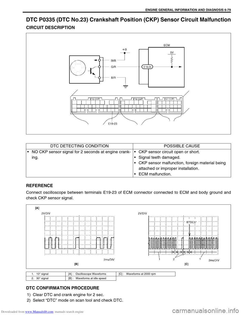
DTC P0335 (DTC No.23) Crankshaft Position (CKP) Sensor Circuit Malfunction
CIRCUIT DESCRIPTION
REFERENCE
Connect oscilloscope between terminals E19-23 of ECM connector connected to ECM and body ground and
check CKP sensor signal.
DTC CONFIRMATION PROCEDURE
1) Clear DTC and crank engine for 2 sec.
2) Select “DTC” mode on scan tool and check DTC.
DTC DETECTING CONDITION POSSIBLE CAUSE
NO CKP sensor signal for 2 seconds at engine crank-
ing.CKP sensor circuit open or short.
Signal teeth damaged.
CKP sensor malfunction, foreign material being
attached or improper installation.
ECM malfunction.
1. 10° signal [A] : Oscilloscope Waveforms [C] : Waveforms at 2000 rpm
2. 30° signal [B] : Waveforms at idle speed
Page 443 of 687

Downloaded from www.Manualslib.com manuals search engine 6-86 ENGINE GENERAL INFORMATION AND DIAGNOSIS
2) Start engine and warm it up to normal operating temperature (70 – 110 °C, 158 – 230 °F) and run it at idle
for 5 min.
3) Increase vehicle speed to 50 – 55 mph, 80 – 88 km/h in 5th gear or in “D” range.
4) Hold throttle valve at that opening position for 2 min. or longer.
5) Increase engine speed to 4000 r/min. in 3rd gear or in “2” range.
6) Release accelerator pedal and with engine brake applied, keep vehicle coasting (fuel cut condition) till
engine speed reaches 1500 r/min.
7) Stop vehicle (don’t turn ignition switch OFF) and confirm test results according to following “Test Result Con-
firmation Flow Table.”
Test Result Confirmation Flow Table
INSPECTION
Step Action Yes No
1 Check DTC in “DTC” mode and pending DTC in
“ON BOARD TEST”.
Is DTC or pending DTC displayed?Proceed to applicable
DTC flow table.Go to Step 2.
2 Set scan tool to “READINESS TESTS” mode
and check if testing has been completed.
Is test completed?No DTC is detected.
(Confirmation test is com-
pleted)Repeat DTC confirmation
procedure.
Step Action Yes No
1Was “Engine Diag. Flow Table” performed? Go to Step 2. Go to “Engine Diag. Flow
Table”.
2 1) Turn ignition switch ON.
2) Does EGR stepper motor operation for 0.6
second after ignition switch OFF?Go to Step 3. Go to Step 6.
3 With ignition switch at OFF, check voltage
between E19-28, 17, 29, 18 terminals of ECM
and body ground. See Fig. 2.
Is voltage about 0 V?Go to Step 4. Go to Step 8.
Page 632 of 687

Downloaded from www.Manualslib.com manuals search engine ENGINE AND EMISSION CONTROL SYSTEM 6E-27
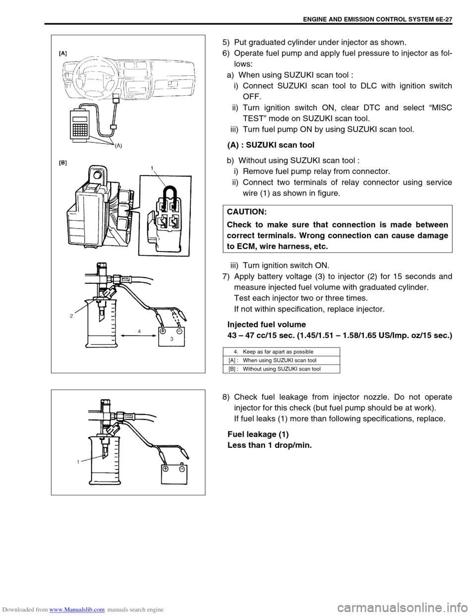
5) Put graduated cylinder under injector as shown.
6) Operate fuel pump and apply fuel pressure to injector as fol-
lows:
a) When using SUZUKI scan tool :
i) Connect SUZUKI scan tool to DLC with ignition switch
OFF.
ii) Turn ignition switch ON, clear DTC and select “MISC
TEST” mode on SUZUKI scan tool.
iii) Turn fuel pump ON by using SUZUKI scan tool.
(A) : SUZUKI scan tool
b) Without using SUZUKI scan tool :
i) Remove fuel pump relay from connector.
ii) Connect two terminals of relay connector using service
wire (1) as shown in figure.
iii) Turn ignition switch ON.
7) Apply battery voltage (3) to injector (2) for 15 seconds and
measure injected fuel volume with graduated cylinder.
Test each injector two or three times.
If not within specification, replace injector.
Injected fuel volume
43 – 47 cc/15 sec. (1.45/1.51 – 1.58/1.65 US/Imp. oz/15 sec.)
8) Check fuel leakage from injector nozzle. Do not operate
injector for this check (but fuel pump should be at work).
If fuel leaks (1) more than following specifications, replace.
Fuel leakage (1)
Less than 1 drop/min. CAUTION:
Check to make sure that connection is made between
correct terminals. Wrong connection can cause damage
to ECM, wire harness, etc.
4. Keep as far apart as possible
[A] : When using SUZUKI scan tool
[B] : Without using SUZUKI scan tool
Page 657 of 687

Downloaded from www.Manualslib.com manuals search engine 6F-8 IGNITION SYSTEM (ELECTRONIC IGNITION SYSTEM)
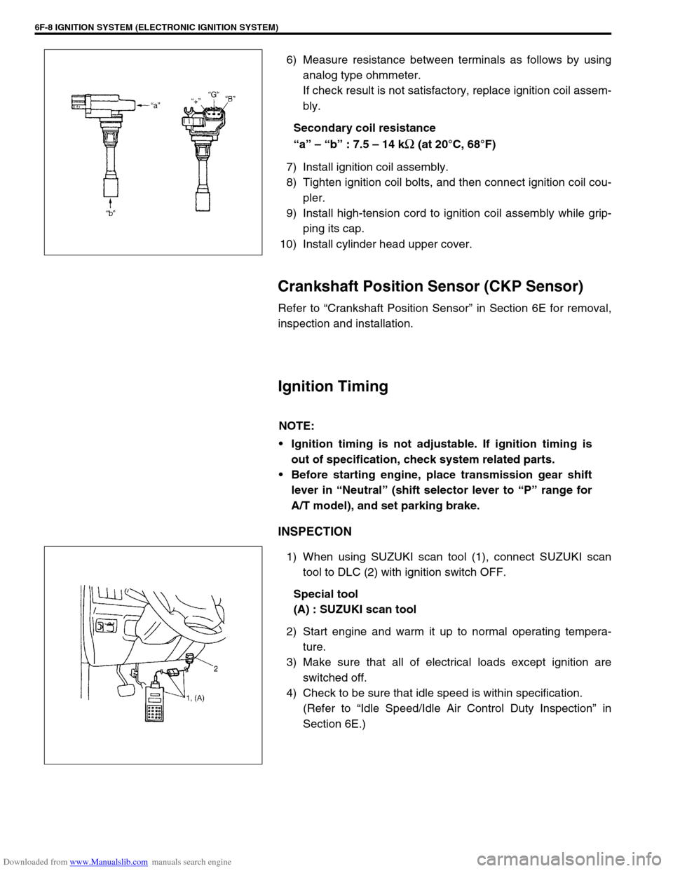
6) Measure resistance between terminals as follows by using
analog type ohmmeter.
If check result is not satisfactory, replace ignition coil assem-
bly.
Secondary coil resistance
“a” – “b” : 7.5 – 14 k
Ω (at 20°C, 68°F)
7) Install ignition coil assembly.
8) Tighten ignition coil bolts, and then connect ignition coil cou-
pler.
9) Install high-tension cord to ignition coil assembly while grip-
ping its cap.
10) Install cylinder head upper cover.
Crankshaft Position Sensor (CKP Sensor)
Refer to “Crankshaft Position Sensor” in Section 6E for removal,
inspection and installation.
Ignition Timing
INSPECTION
1) When using SUZUKI scan tool (1), connect SUZUKI scan
tool to DLC (2) with ignition switch OFF.
Special tool
(A) : SUZUKI scan tool
2) Start engine and warm it up to normal operating tempera-
ture.
3) Make sure that all of electrical loads except ignition are
switched off.
4) Check to be sure that idle speed is within specification.
(Refer to “Idle Speed/Idle Air Control Duty Inspection” in
Section 6E.)
NOTE:
Ignition timing is not adjustable. If ignition timing is
out of specification, check system related parts.
Before starting engine, place transmission gear shift
lever in “Neutral” (shift selector lever to “P” range for
A/T model), and set parking brake.
Page 660 of 687

Downloaded from www.Manualslib.com manuals search engine CRANKING SYSTEM 6G-1
6F1
6F2
6H
7C1
7D
7E
7C1
7B1
7C1
7D
7E
7F
8A
8B
8C
8D
8E
6G
7A1
10A
10B
SECTION 6G
CRANKING SYSTEM
CONTENTS
General Description ....................................... 6G-2
Cranking Circuit ............................................ 6G-2
Diagnosis ........................................................ 6G-2
Diagnosis Table ........................................... 6G-2Performance Test .........................................6G-4
On-Vehicle Service .........................................6G-5
Starting Motor ...............................................6G-5
Specifications..................................................6G-7
WARNING:
For vehicles equipped with Supplemental Restraint (Air Bag) System:
Service on and around the air bag system components or wiring must be performed only by an
authorized SUZUKI dealer. Refer to “Air Bag System Components and Wiring Location View” under
“General Description” in air bag system section in order to confirm whether you are performing ser-
vice on or near the air bag system components or wiring. Please observe all WARNINGS and “Ser-
vice Precautions” under “On-Vehicle Service” in air bag system section before performing service
on or around the air bag system components or wiring. Failure to follow WARNINGS could result in
unintentional activation of the system or could render the system inoperative. Either of these two
conditions may result in severe injury.
Technical service work must be started at least 90 seconds after the ignition switch is turned to the
“LOCK” position and the negative cable is disconnected from the battery. Otherwise, the system
may be activated by reserve energy in the Sensing and Diagnostic Module (SDM).
NOTE:
Starting motor varies depending on specifications, etc. Therefore, be sure to check model and speci-
fication of vehicle being serviced before replacing parts.