ECU SUZUKI JIMNY 2005 3.G Service Workshop Manual
[x] Cancel search | Manufacturer: SUZUKI, Model Year: 2005, Model line: JIMNY, Model: SUZUKI JIMNY 2005 3.GPages: 687, PDF Size: 13.38 MB
Page 9 of 687
Downloaded from www.Manualslib.com manuals search engine 0A-4 GENERAL INFORMATION
Servicing and handling
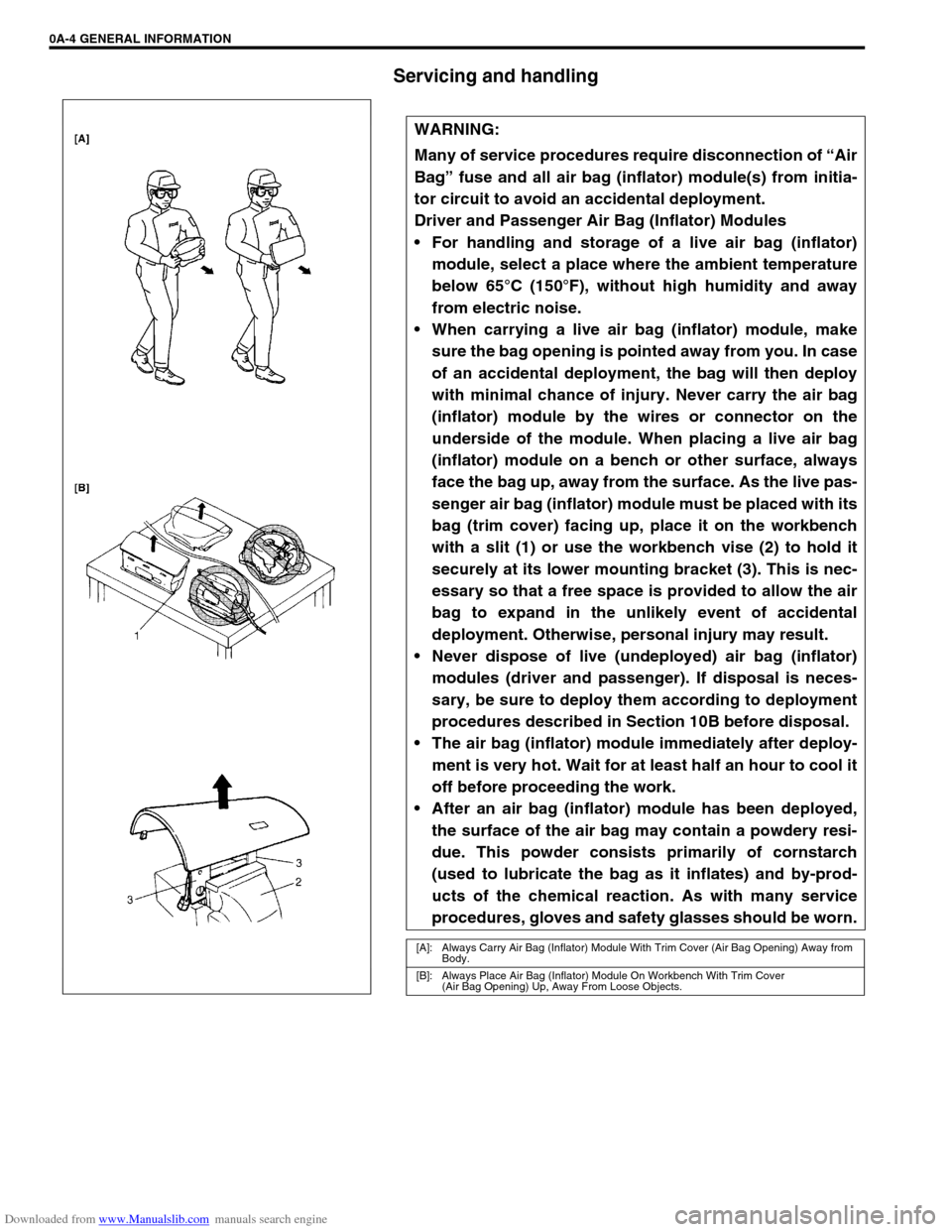
WARNING:
Many of service procedures require disconnection of “Air
Bag” fuse and all air bag (inflator) module(s) from initia-
tor circuit to avoid an accidental deployment.
Driver and Passenger Air Bag (Inflator) Modules
For handling and storage of a live air bag (inflator)
module, select a place where the ambient temperature
below 65°C (150°F), without high humidity and away
from electric noise.
When carrying a live air bag (inflator) module, make
sure the bag opening is pointed away from you. In case
of an accidental deployment, the bag will then deploy
with minimal chance of injury. Never carry the air bag
(inflator) module by the wires or connector on the
underside of the module. When placing a live air bag
(inflator) module on a bench or other surface, always
face the bag up, away from the surface. As the live pas-
senger air bag (inflator) module must be placed with its
bag (trim cover) facing up, place it on the workbench
with a slit (1) or use the workbench vise (2) to hold it
securely at its lower mounting bracket (3). This is nec-
essary so that a free space is provided to allow the air
bag to expand in the unlikely event of accidental
deployment. Otherwise, personal injury may result.
Never dispose of live (undeployed) air bag (inflator)
modules (driver and passenger). If disposal is neces-
sary, be sure to deploy them according to deployment
procedures described in Section 10B before disposal.
The air bag (inflator) module immediately after deploy-
ment is very hot. Wait for at least half an hour to cool it
off before proceeding the work.
After an air bag (inflator) module has been deployed,
the surface of the air bag may contain a powdery resi-
due. This powder consists primarily of cornstarch
(used to lubricate the bag as it inflates) and by-prod-
ucts of the chemical reaction. As with many service
procedures, gloves and safety glasses should be worn.
[A]: Always Carry Air Bag (Inflator) Module With Trim Cover (Air Bag Opening) Away from
Body.
[B]: Always Place Air Bag (Inflator) Module On Workbench With Trim Cover
(Air Bag Opening) Up, Away From Loose Objects.
Page 16 of 687
Downloaded from www.Manualslib.com manuals search engine GENERAL INFORMATION 0A-11
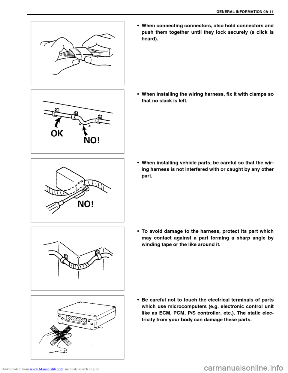
When connecting connectors, also hold connectors and
push them together until they lock securely (a click is
heard).
When installing the wiring harness, fix it with clamps so
that no slack is left.
When installing vehicle parts, be careful so that the wir-
ing harness is not interfered with or caught by any other
part.
To avoid damage to the harness, protect its part which
may contact against a part forming a sharp angle by
winding tape or the like around it.
Be careful not to touch the electrical terminals of parts
which use microcomputers (e.g. electronic control unit
like as ECM, PCM, P/S controller, etc.). The static elec-
tricity from your body can damage these parts.
Page 25 of 687
Downloaded from www.Manualslib.com manuals search engine 0A-20 GENERAL INFORMATION
When Using Floor Jack
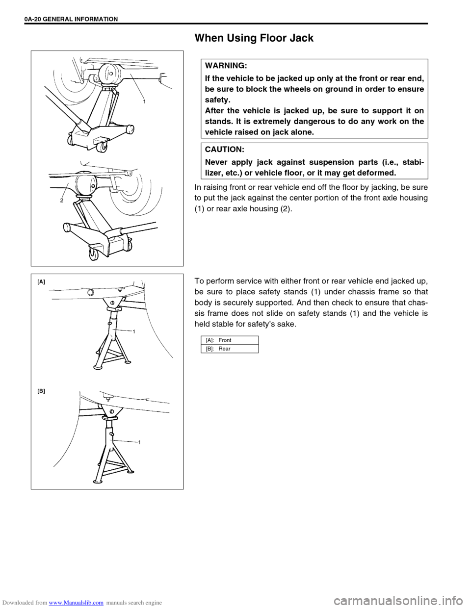
In raising front or rear vehicle end off the floor by jacking, be sure
to put the jack against the center portion of the front axle housing
(1) or rear axle housing (2).
To perform service with either front or rear vehicle end jacked up,
be sure to place safety stands (1) under chassis frame so that
body is securely supported. And then check to ensure that chas-
sis frame does not slide on safety stands (1) and the vehicle is
held stable for safety’s sake. WARNING:
If the vehicle to be jacked up only at the front or rear end,
be sure to block the wheels on ground in order to ensure
safety.
After the vehicle is jacked up, be sure to support it on
stands. It is extremely dangerous to do any work on the
vehicle raised on jack alone.
CAUTION:
Never apply jack against suspension parts (i.e., stabi-
lizer, etc.) or vehicle floor, or it may get deformed.
[A]: Front
[B]: Rear
Page 38 of 687
Downloaded from www.Manualslib.com manuals search engine MAINTENANCE AND LUBRICATION 0B-7
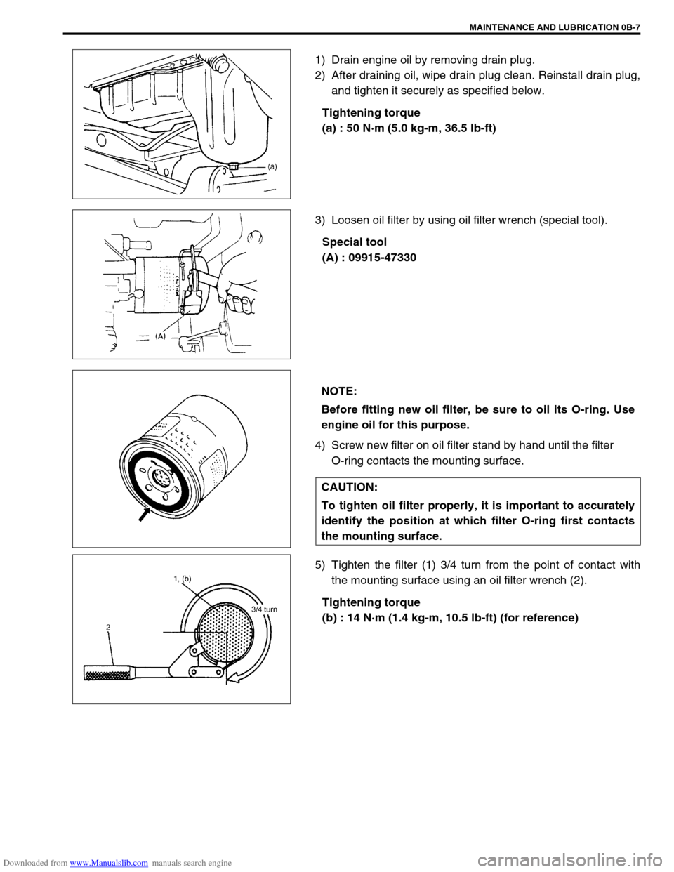
1) Drain engine oil by removing drain plug.
2) After draining oil, wipe drain plug clean. Reinstall drain plug,
and tighten it securely as specified below.
Tightening torque
(a) : 50 N·m (5.0 kg-m, 36.5 lb-ft)
3) Loosen oil filter by using oil filter wrench (special tool).
Special tool
(A) : 09915-47330
4) Screw new filter on oil filter stand by hand until the filter
O-ring contacts the mounting surface.
5) Tighten the filter (1) 3/4 turn from the point of contact with
the mounting surface using an oil filter wrench (2).
Tightening torque
(b) : 14 N·m (1.4 kg-m, 10.5 lb-ft) (for reference)
NOTE:
Before fitting new oil filter, be sure to oil its O-ring. Use
engine oil for this purpose.
CAUTION:
To tighten oil filter properly, it is important to accurately
identify the position at which filter O-ring first contacts
the mounting surface.
Page 40 of 687
Downloaded from www.Manualslib.com manuals search engine MAINTENANCE AND LUBRICATION 0B-9
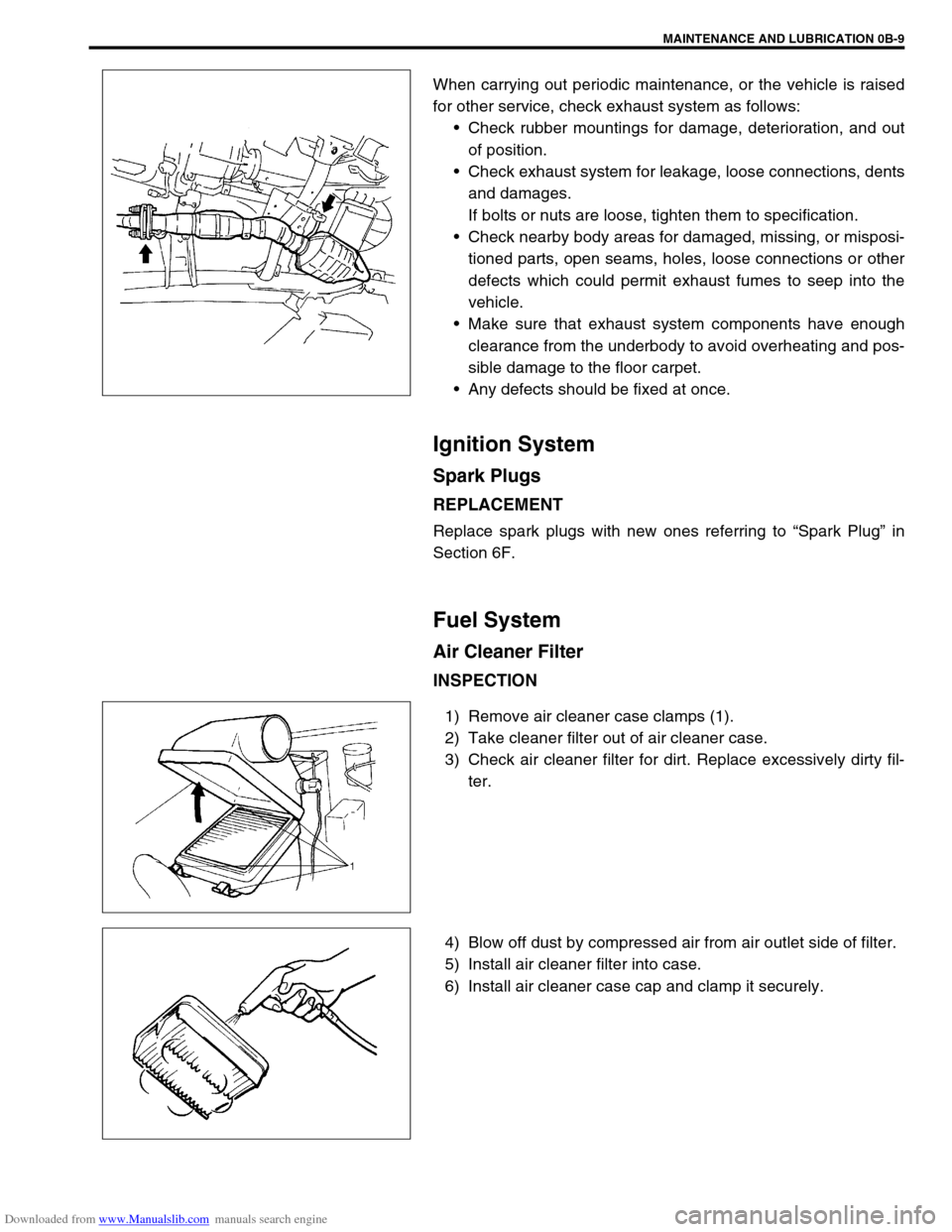
When carrying out periodic maintenance, or the vehicle is raised
for other service, check exhaust system as follows:
Check rubber mountings for damage, deterioration, and out
of position.
Check exhaust system for leakage, loose connections, dents
and damages.
If bolts or nuts are loose, tighten them to specification.
Check nearby body areas for damaged, missing, or misposi-
tioned parts, open seams, holes, loose connections or other
defects which could permit exhaust fumes to seep into the
vehicle.
Make sure that exhaust system components have enough
clearance from the underbody to avoid overheating and pos-
sible damage to the floor carpet.
Any defects should be fixed at once.
Ignition System
Spark Plugs
REPLACEMENT
Replace spark plugs with new ones referring to “Spark Plug” in
Section 6F.
Fuel System
Air Cleaner Filter
INSPECTION
1) Remove air cleaner case clamps (1).
2) Take cleaner filter out of air cleaner case.
3) Check air cleaner filter for dirt. Replace excessively dirty fil-
ter.
4) Blow off dust by compressed air from air outlet side of filter.
5) Install air cleaner filter into case.
6) Install air cleaner case cap and clamp it securely.
Page 41 of 687
Downloaded from www.Manualslib.com manuals search engine 0B-10 MAINTENANCE AND LUBRICATION
REPLACEMENT
Replace air cleaner filter with new one according to steps 1), 2)
and 5), 6) of inspection procedure.
Fuel Lines and Connections
INSPECTION
1) Visually inspect fuel lines and connections for evidence of
fuel leakage, hose cracking and damage. Make sure all
clamps are secure.
Repair leaky joints, if any.
Replace hoses that are suspected of being cracked.
Fuel Filter
REPLACEMENT
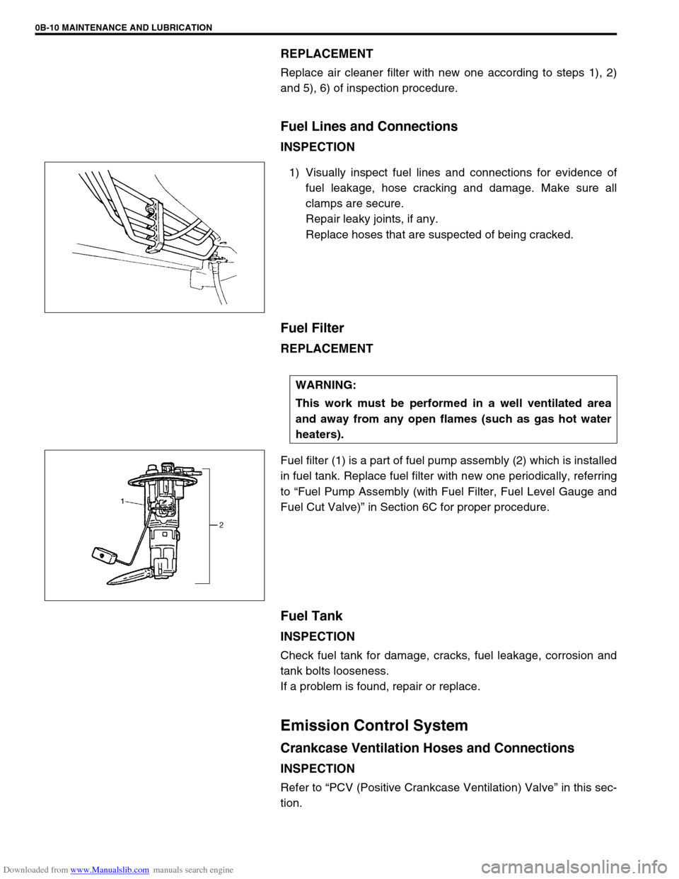
Fuel filter (1) is a part of fuel pump assembly (2) which is installed
in fuel tank. Replace fuel filter with new one periodically, referring
to “Fuel Pump Assembly (with Fuel Filter, Fuel Level Gauge and
Fuel Cut Valve)” in Section 6C for proper procedure.
Fuel Tank
INSPECTION
Check fuel tank for damage, cracks, fuel leakage, corrosion and
tank bolts looseness.
If a problem is found, repair or replace.
Emission Control System
Crankcase Ventilation Hoses and Connections
INSPECTION
Refer to “PCV (Positive Crankcase Ventilation) Valve” in this sec-
tion.
WARNING:
This work must be performed in a well ventilated area
and away from any open flames (such as gas hot water
heaters).
Page 50 of 687
Downloaded from www.Manualslib.com manuals search engine MAINTENANCE AND LUBRICATION 0B-19
Power Steering (P/S) System (if equipped)
INSPECTION
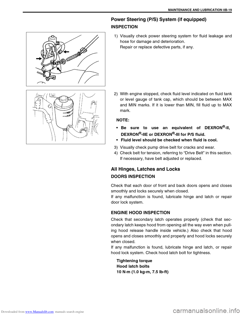
1) Visually check power steering system for fluid leakage and
hose for damage and deterioration.
Repair or replace defective parts, if any.
2) With engine stopped, check fluid level indicated on fluid tank
or level gauge of tank cap, which should be between MAX
and MIN marks. If it is lower than MIN, fill fluid up to MAX
mark.
3) Visually check pump drive belt for cracks and wear.
4) Check belt for tension, referring to “Drive Belt” in this section.
If necessary, have belt adjusted or replaced.
All Hinges, Latches and Locks
DOORS INSPECTION
Check that each door of front and back doors opens and closes
smoothly and locks securely when closed.
If any malfunction is found, lubricate hinge and latch or repair
door lock system.
ENGINE HOOD INSPECTION
Check that secondary latch operates properly (check that sec-
ondary latch keeps hood from opening all the way even when pull-
ing hood release handle inside vehicle.) Also check that hood
opens and closes smoothly and properly and hood locks securely
when closed.
If any malfunction is found, lubricate hinge and latch, or repair
hood lock system. Check hood latch bolt for tightness.
Tightening torque
Hood latch bolts
10 N·m (1.0 kg-m, 7.5 lb-ft)
NOTE:
Be sure to use an equivalent of DEXRON
®-II,
DEXRON
®-IIE or DEXRON®-III for P/S fluid.
Fluid level should be checked when fluid is cool.
Page 51 of 687

Downloaded from www.Manualslib.com manuals search engine 0B-20 MAINTENANCE AND LUBRICATION
Final Inspection
SEATS
Check that seat slides smoothly and locks securely at any position. Also check that reclining mechanism of front
seat back allows it to be locked at any angle.
SEAT BELT
Inspect belt system including webbing, buckles, latch plates, retractors and anchors for damage or wear.
If “REPLACE BELT” label on front seat belt is visible, replace belt. Check that seat belt is securely locked.
BATTERY ELECTROLYTE LEVEL CHECK
Check that the electrolyte level of all battery cells is between the upper and lower level lines on the case. If bat-
tery is equipped with built-in indicator, check battery condition by the indicator.
ACCELERATOR PEDAL OPERATION
Check that pedal operates smoothly without getting caught or interfered by any other part.
ENGINE START
Check engine start for readiness.
On automatic transmission vehicles, try to start the engine in each select lever position. The starting motor
should crank only in “P” (Park) or “N” (Neutral).
On manual transmission vehicles, place the shift lever in “Neutral,” depress clutch pedal fully any try to start.
EXHAUST SYSTEM CHECK
Check for leakage, cracks or loose supports.
CLUTCH (FOR MANUAL TRANSMISSION)
Check for the following.
Clutch is completely released when depressing clutch pedal,
No slipping clutch occurs when releasing pedal and accelerating.
Clutch itself is free from any abnormal condition. WARNING:
When carrying out road tests, select a safe place where no man or no running vehicle is seen so as to
prevent any accident.
WARNING:
Before performing the following check, be sure to have enough room around the vehicle. Then, firmly
apply both the parking brake and the regular brakes. Do not use the accelerator pedal. If the engine
starts, be ready to turn off the ignition promptly. Take these precautions because the vehicle could
move without warning and possibly cause personal injury or property damage.
Page 87 of 687
Downloaded from www.Manualslib.com manuals search engine 1B-26 AIR CONDITIONING (OPTIONAL)
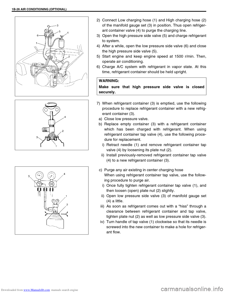
2) Connect Low charging hose (1) and High charging hose (2)
of the manifold gauge set (3) in position. Thus open refriger-
ant container valve (4) to purge the charging line.
3) Open the high pressure side valve (5) and charge refrigerant
to system.
4) After a while, open the low pressure side valve (6) and close
the high pressure side valve (5).
5) Start engine and keep engine speed at 1500 r/min. Then,
operate air conditioning.
6) Charge A/C system with refrigerant in vapor state. At this
time, refrigerant container should be held upright.
7) When refrigerant container (3) is emptied, use the following
procedure to replace refrigerant container with a new refrig-
erant container (3).
a) Close low pressure valve.
b) Replace empty container (3) with a refrigerant container
which has been charged with refrigerant. When using
refrigerant container tap valve (4), use the following proce-
dure for replacement.
i) Retract needle (1) and remove refrigerant container tap
valve (4) by loosening its plate nut (2).
ii) Install previously-removed refrigerant container tap valve
(4) to a new refrigerant container (3).
c) Purge any air existing in center charging hose
When using refrigerant container tap valve, use the follow-
ing procedure to purge air.
i) Once fully tighten refrigerant container tap valve (1), and
then loosen (open) plate nut (2) slightly.
ii) Open low pressure side valve (3) of manifold gauge set
(4) a little.
iii) As soon as refrigerant comes out with a “hiss” through a
clearance between refrigerant container and tap valve,
tighten plate nut (2) as well as low pressure side valve (3).
iv) Turn handle of tap valve (1) clockwise so that its needle is
screwed into the new container to make a hole for refriger-
ant flow. WARNING:
Make sure that high pressure side valve is closed
securely.
Page 146 of 687
Downloaded from www.Manualslib.com manuals search engine POWER STEERING (P/S) SYSTEM (If equipped) 3B1-15
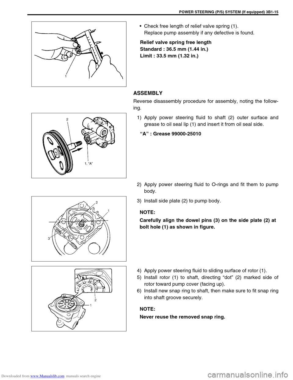
Check free length of relief valve spring (1).
Replace pump assembly if any defective is found.
Relief valve spring free length
Standard : 36.5 mm (1.44 in.)
Limit : 33.5 mm (1.32 in.)
ASSEMBLY
Reverse disassembly procedure for assembly, noting the follow-
ing.
1) Apply power steering fluid to shaft (2) outer surface and
grease to oil seal lip (1) and insert it from oil seal side.
“A” : Grease 99000-25010
2) Apply power steering fluid to O-rings and fit them to pump
body.
3) Install side plate (2) to pump body.
4) Apply power steering fluid to sliding surface of rotor (1).
5) Install rotor (1) to shaft, directing “dot” (2) marked side of
rotor toward pump cover (facing up).
6) Install new snap ring to shaft, then make sure to fit snap ring
into shaft groove securely.
NOTE:
Carefully align the dowel pins (3) on the side plate (2) at
bolt hole (1) as shown in figure.
NOTE:
Never reuse the removed snap ring.