Remove instrument panel SUZUKI JIMNY 2005 3.G Service Workshop Manual
[x] Cancel search | Manufacturer: SUZUKI, Model Year: 2005, Model line: JIMNY, Model: SUZUKI JIMNY 2005 3.GPages: 687, PDF Size: 13.38 MB
Page 1 of 687

Downloaded from www.Manualslib.com manuals search engine IMPORTANT
WARNING/CAUTION/NOTE
Please read this manual and follow its instructions carefully. To emphasize special information, the words
WARNING, CAUTION
and NOTE
have special meanings. Pay special attention to the messages highlighted by
these signal words.
WARNING:
Indicates a potential hazard that could result in death or injury.
CAUTION:
Indicates a potential hazard that could result in vehicle damage.
NOTE:
Indicates special information to make maintenance easier or instructions clearer.
WARNING:
This service manual is intended for authorized Suzuki dealers and qualified service mechanics only.
Inexperienced mechanics or mechanics without the proper tools and equipment may not be able to
properly perform the services described in this manual.
Improper repair may result in injury to the mechanic and may render the vehicle unsafe for the driver
and passengers.
WARNING:
For vehicles equipped with a Supplemental Restraint or Air Bag System:
• Service on and around the air bag system components or wiring must be performed only by an
authorized SUZUKI dealer. Refer to “Air Bag System Components and Wiring Location View” under
“General Description” in air bag system section in order to confirm whether you are performing ser-
vice on or near the air bag system components or wiring. Please observe all WARNINGS and “Ser-
vice Precautions” under “On-Vehicle Service” in air bag system section before performing service
on or around the air bag system components or wiring. Failure to follow WARNINGS could result in
unintentional activation of the system or could render the system inoperative. Either of these two
conditions may result in severe injury.
If the air bag system and another vehicle system both need repair, Suzuki recommends that the air
bag system be repaired first, to help avoid unintended air bag system activation.
Do not modify the steering wheel, instrument panel or any other air bag system component on or
around air bag system components or wiring. Modifications can adversely affect air bag system
performance and lead to injury.
If the vehicle will be exposed to temperatures over 93°C (200°F), for example, during a paint baking
process, remove the air bag system components, that is air bag or inflator modules, SDM and/or
seat belt with pretensioner, beforehand to avoid component damage or unintended activation.
Page 8 of 687

Downloaded from www.Manualslib.com manuals search engine GENERAL INFORMATION 0A-3
Precautions
Precaution for Vehicles Equipped with a Sup-
plemental Restraint (Air Bag) System
Diagnosis
When troubleshooting air bag system, be sure to follow “Air
Bag Diagnostic System Check” in Section 10B. Bypassing
these procedures may result in extended diagnostic time,
incorrect diagnosis, and incorrect parts replacement.
Never use electrical test equipment other than that specified
in this manual. WARNING:
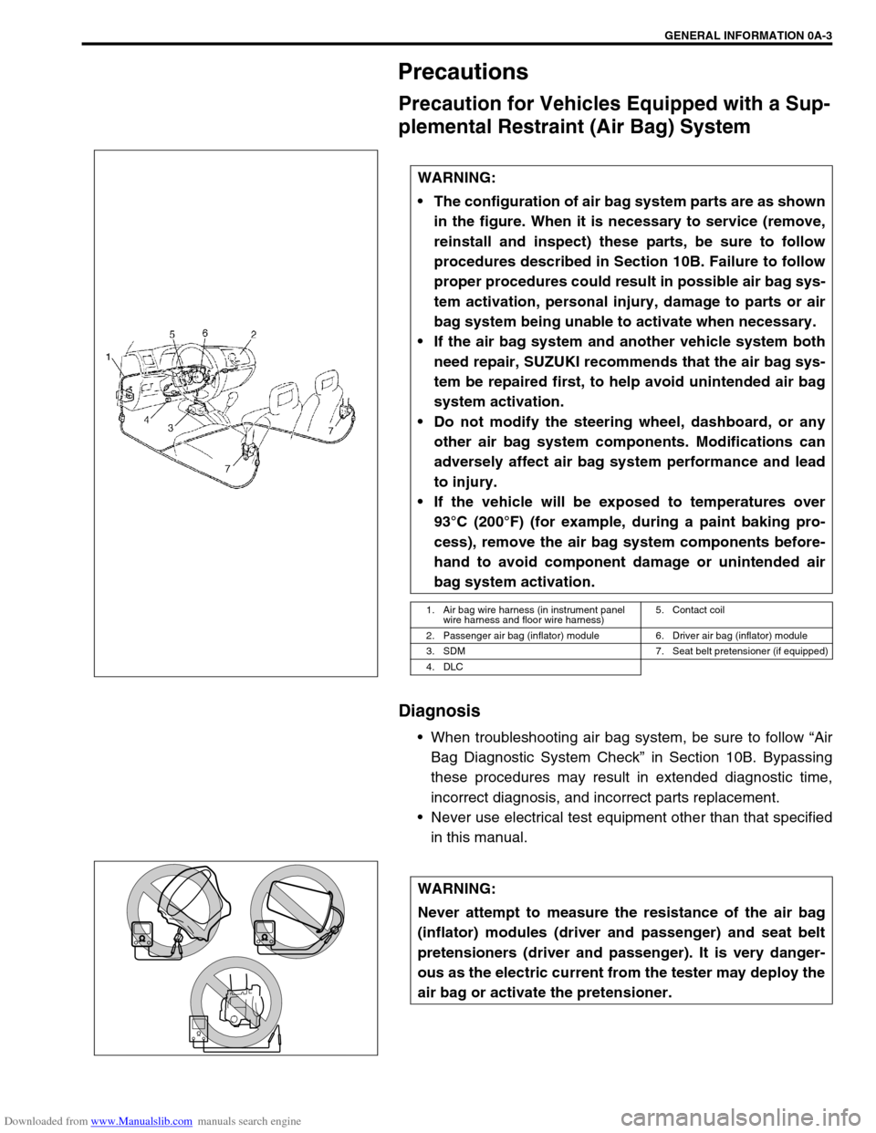
The configuration of air bag system parts are as shown
in the figure. When it is necessary to service (remove,
reinstall and inspect) these parts, be sure to follow
procedures described in Section 10B. Failure to follow
proper procedures could result in possible air bag sys-
tem activation, personal injury, damage to parts or air
bag system being unable to activate when necessary.
If the air bag system and another vehicle system both
need repair, SUZUKI recommends that the air bag sys-
tem be repaired first, to help avoid unintended air bag
system activation.
Do not modify the steering wheel, dashboard, or any
other air bag system components. Modifications can
adversely affect air bag system performance and lead
to injury.
If the vehicle will be exposed to temperatures over
93°C (200°F) (for example, during a paint baking pro-
cess), remove the air bag system components before-
hand to avoid component damage or unintended air
bag system activation.
1. Air bag wire harness (in instrument panel
wire harness and floor wire harness)5. Contact coil
2. Passenger air bag (inflator) module 6. Driver air bag (inflator) module
3. SDM 7. Seat belt pretensioner (if equipped)
4. DLC
WARNING:
Never attempt to measure the resistance of the air bag
(inflator) modules (driver and passenger) and seat belt
pretensioners (driver and passenger). It is very danger-
ous as the electric current from the tester may deploy the
air bag or activate the pretensioner.
Page 60 of 687

Downloaded from www.Manualslib.com manuals search engine HEATER AND VENTILATION 1A-7
Heater Blower Fan Switch
INSPECTION
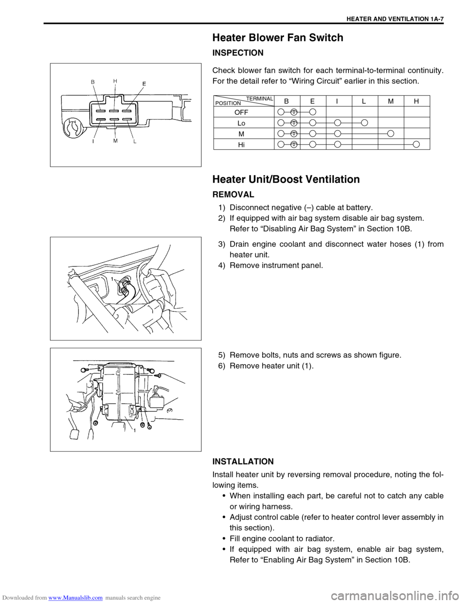
Check blower fan switch for each terminal-to-terminal continuity.
For the detail refer to “Wiring Circuit” earlier in this section.
Heater Unit/Boost Ventilation
REMOVAL
1) Disconnect negative (–) cable at battery.
2) If equipped with air bag system disable air bag system.
Refer to “Disabling Air Bag System” in Section 10B.
3) Drain engine coolant and disconnect water hoses (1) from
heater unit.
4) Remove instrument panel.
5) Remove bolts, nuts and screws as shown figure.
6) Remove heater unit (1).
INSTALLATION
Install heater unit by reversing removal procedure, noting the fol-
lowing items.
When installing each part, be careful not to catch any cable
or wiring harness.
Adjust control cable (refer to heater control lever assembly in
this section).
Fill engine coolant to radiator.
If equipped with air bag system, enable air bag system,
Refer to “Enabling Air Bag System” in Section 10B.
TERMINAL
POSITIONBEI L MH
OFF
Lo
M
Hi
Page 96 of 687

Downloaded from www.Manualslib.com manuals search engine AIR CONDITIONING (OPTIONAL) 1B-35
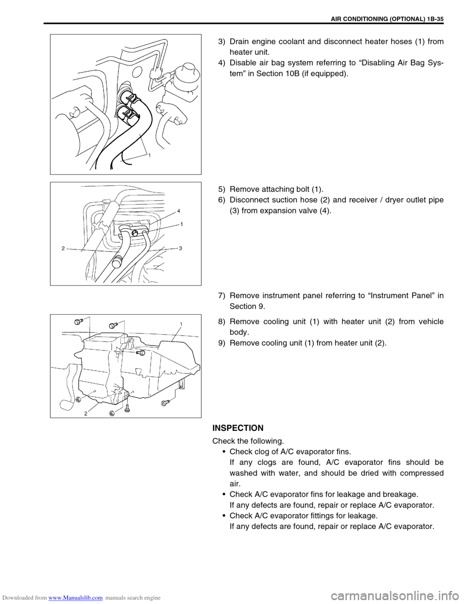
3) Drain engine coolant and disconnect heater hoses (1) from
heater unit.
4) Disable air bag system referring to “Disabling Air Bag Sys-
tem” in Section 10B (if equipped).
5) Remove attaching bolt (1).
6) Disconnect suction hose (2) and receiver / dryer outlet pipe
(3) from expansion valve (4).
7) Remove instrument panel referring to “Instrument Panel” in
Section 9.
8) Remove cooling unit (1) with heater unit (2) from vehicle
body.
9) Remove cooling unit (1) from heater unit (2).
INSPECTION
Check the following.
Check clog of A/C evaporator fins.
If any clogs are found, A/C evaporator fins should be
washed with water, and should be dried with compressed
air.
Check A/C evaporator fins for leakage and breakage.
If any defects are found, repair or replace A/C evaporator.
Check A/C evaporator fittings for leakage.
If any defects are found, repair or replace A/C evaporator.
Page 164 of 687

Downloaded from www.Manualslib.com manuals search engine STEERING WHEEL AND COLUMN 3C-11
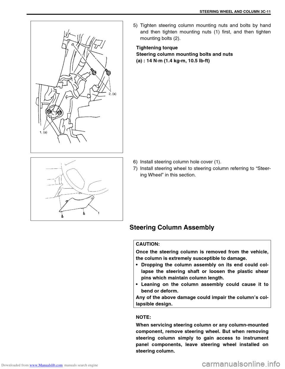
5) Tighten steering column mounting nuts and bolts by hand
and then tighten mounting nuts (1) first, and then tighten
mounting bolts (2).
Tightening torque
Steering column mounting bolts and nuts
(a) : 14 N·m (1.4 kg-m, 10.5 lb-ft)
6) Install steering column hole cover (1).
7) Install steering wheel to steering column referring to “Steer-
ing Wheel” in this section.
Steering Column Assembly
CAUTION:
Once the steering column is removed from the vehicle,
the column is extremely susceptible to damage.
Dropping the column assembly on its end could col-
lapse the steering shaft or loosen the plastic shear
pins which maintain column length.
Leaning on the column assembly could cause it to
bend or deform.
Any of the above damage could impair the column’s col-
lapsible design.
NOTE:
When servicing steering column or any column-mounted
component, remove steering wheel. But when removing
steering column simply to gain access to instrument
panel components, leave steering wheel installed on
steering column.