Speed SUZUKI JIMNY 2005 3.G Service Workshop Manual
[x] Cancel search | Manufacturer: SUZUKI, Model Year: 2005, Model line: JIMNY, Model: SUZUKI JIMNY 2005 3.GPages: 687, PDF Size: 13.38 MB
Page 26 of 687

Downloaded from www.Manualslib.com manuals search engine GENERAL INFORMATION 0A-21
Abbreviations May Be Used In This Manual
Abbreviations
AABC
ATDC
API
ATF
ALR
AC
A/T
A/C
ABDC
A/F
A-ELRAnti-lock Brake System
After Top Dead Center
American Petroleum Institute
Automatic Transmission Fluid
Automatic Locking Retractor
Alternating Current
Automatic Transmission
Air Conditioning
After Bottom Dead Center
Air Fuel Mixture Ratio
Automatic-Emergency
Locking RetractorEEBCM
ECM
ECT Sensor
EGR
EGRT Sensor
EFE Heater
ELR
EPS
EVAP
EVAP CanisterElectronic Brake Control Module,
ABS Control Module
Engine Control Module
Engine Coolant Temperature
Sensor (Water Temp. Sensor,
WTS)
Exhaust Gas Recirculation
EGR Temperature Sensor
(Recirculated Exhaust Gas Temp.
Sensor, REGTS)
Early Fuel Evaporation
Heater (Positive Temperature
Coefficient, PTC Heater)
Emergency Locking Retractor
Electronic Power Steering
Evaporative Emission
Evaporative Emission Canister
(Charcoal Canister) BB+
BTDC
BBDCBattery Positive Voltage
Before Top Dead Center
Before Bottom Dead Center
CCKT
CMP Sensor
CO
CPP Switch
CPU
CRSCircuit
Camshaft Position Sensor
(Crank Angle Sensor, CAS)
Carbon Monoxide
Clutch Pedal Position Switch
(Clutch Switch, Clutch Start
Switch)
Central Processing Unit
Child Restraint SystemF 4WD 4 Wheel Drive
GGEN
GNDGenerator
Ground
HHC
HO2SHydrocarbons
Heated Oxygen Sensor
DDC
DLC
DOHC
DOJ
DRL
DTCDirect Current
Data Link Connector
(Assembly Line Diag. Link, ALDL,
Serial Data Link, SDL)
Double Over Head Camshaft
Double Offset Joint
Daytime Running Light
Diagnostic Trouble Code
(Diagnostic Code)IIAC Valve
IAT Sensor
ICM
IG
ISC ActuatorIdle Air Control Valve (Idle Speed
Control Solenoid Valve, ISC
Solenoid Valve)
Intake Air Temperature Sensor
(Air temperature Sensor, ATS)
Immobilizer Control Module
Ignition
Idle Speed Control Actuator
(Motor)
Page 27 of 687

Downloaded from www.Manualslib.com manuals search engine 0A-22 GENERAL INFORMATION
LLH
LSPVLeft Hand
Load Sensing Proportioning Valve
TTBI
TCC
TCM
TP Sensor
TVV
TWC
2WDThrottle Body Fuel Injection
(Single-Point Fuel Injection, SPI)
Torque Converter Clutch
Transmission Control Module
(A/T Controller, A/T Control Mod-
ule)
Throttle Position Sensor
Thermal Vacuum Valve
(Thermal Vacuum Switching Valve,
TVSV, Bimetal Vacuum Switching
Valve, BVSV)
Three Way Catalytic Converter
(Three Way Catalyst)
2 Wheel Drive MMAF Sensor
MAP Sensor
Max
MFI
Min
MIL
M/TMass Air Flow Sensor
(Air Flow Sensor, AFS, Air Flow
Meter, AFM)
Manifold Absolute Pressure
Sensor (Pressure Sensor, PS)
Maximum
Multiport Fuel Injection
(Multipoint Fuel Injection)
Minimum
Malfunction Indicator Lamp
(“CHECK ENGINE” Light)
Manual Transmission
N NOx Nitrogen Oxides VVIN
VSSVehicle Identification Number
Vehicle Speed Sensor
OOBD
O/D
OHCOn-Board Diagnostic System
(Self-Diagnosis Function)
Overdrive
Over Head CamshaftWWU-OC
WU-TWCWarm Up Oxidation Catalytic
Converter
Warm Up Three Way Catalytic
Converter
PPNP
P/S
PSP Switch
PCM
PCVPark/Neutral Position
Power Steering
Power Steering Pressure Switch
(P/S Pressure Switch)
Powertrain Control Module
Positive Crankcase Ventilation
R RH Right Hand
SSAE
SDM
SFI
SOHCSociety of Automotive Engineers
Sensing and Diagnostic Module
(Air bag controller, Air bag control
module)
Sequential Multiport Fuel Injection
Single Over Head Camshaft
Page 52 of 687

Downloaded from www.Manualslib.com manuals search engine MAINTENANCE AND LUBRICATION 0B-21
GEARSHIFT OR SELECTOR LEVER (TRANSMISSION)
Check gear shift or selector lever for smooth shifting to all positions and for good performance of transmission in
any position.
With automatic transmission equipped vehicle, also check that shift indicator indicates properly according to
which position selector lever is shifted to.
With automatic transmission equipped vehicle, make sure that vehicle is at complete stop when shifting selector
lever to “P” range position and release all brakes.
BRAKE
Foot Brake
Check the following:
that brake pedal has proper travel,
that brake works properly,
that it is free from noise,
that braking force is applied equally on all wheels,
and that brake do not drag.
Parking Brake
Check that lever has proper travel.
Check to ensure that parking brake is fully effective when the vehicle is stopped on the safe slope and brake
lever is pulled all the way.
STEERING
Check to ensure that steering wheel is free from instability, or abnormally heavy feeling.
Check that the vehicle does not wander or pull to one side.
ENGINE
Check that engine responds readily at all speeds.
Check that engine is free from abnormal noise and abnormal vibration.
BODY, WHEELS AND POWER TRANSMITTING SYSTEM
Check that body, wheels and power transmitting system are free from abnormal noise and abnormal vibration or
any other abnormal condition.
METERS AND GAUGE
Check that speedometer, odometer, fuel meter, temperature gauge, etc. are operating accurately.
LIGHTS
Check that all lights operate properly.
WINDSHIELD DEFROSTER
Periodically check that air comes out from defroster outlet when operating heater or air conditioning.
Set mode control lever to defroster position and fan switch lever to “HI” position for this check. WARNING:
With vehicle parked on a fairly steep slope, make sure nothing is in the way downhill to avoid any per-
sonal injury or property damage. Be prepared to apply regular brake quickly even if vehicle should
start to move.
Page 67 of 687

Downloaded from www.Manualslib.com manuals search engine 1B-6 AIR CONDITIONING (OPTIONAL)
Cool air won’t come
out or insufficient
cooling (A/C system
normal operative)Insufficient or excessive charge of
refrigerantCheck charge of refrigerant and system for
leaks.
Condenser clogged Check condenser.
A/C evaporator clogged or frosted Check A/C evaporator and A/C evaporator
thermistor.
A/C evaporator thermistor faulty Check A/C evaporator thermistor.
Expansion valve faulty Check expansion valve.
Receiver / dryer clogged Check receiver / dryer.
Compressor drive belt loosen or broken Adjust or replace drive belt.
Magnetic clutch faulty Check magnetic clutch.
Compressor faulty Check compressor.
Air in A/C system Replace receiver / dryer, and perform
evacuation and charging.
Air leaking from cooling unit or air duct Repair as necessary.
Heater and ventilation system faulty Check air inlet box (cooling unit), heater
control lever assembly and heater unit
referring to Section 1A.
Blower fan motor faulty Check blower fan motor referring to Sec-
tion 1A.
Excessive compressor oil existing in
A/C systemPull out compressor oil in A/C system cir-
cuit, and replace compressor.
Cool air won’t come
out only intermittentlyWiring connection faulty Repair as necessary.
Expansion valve faulty Check expansion valve.
Excessive moisture in A/C system Replace receiver / dryer, and perform
evacuation and charging.
Magnetic clutch faulty Check magnetic clutch.
Excessive charge of refrigerant Check charge of refrigerant.
Thermal switch faulty Check thermal switch.
Cool air comes out
only at high speedCondenser clogged Check A/C condenser.
Insufficient charge of refrigerant Check charge of refrigerant.
Air in A/C system Replace receiver / dryer, and perform
evacuation and charging.
Compressor drive belt loosen or broken Adjust or replace drive belt.
Compressor faulty Check compressor.
Cool air won’t come
out only at high speedExcessive charge of refrigerant Check charge refrigerant.
A/C evaporator frosted Check A/C evaporator and A/C evaporator
thermistor.
Insufficient velocity of
cooled airA/C evaporator clogged or frosted Check A/C evaporator and A/C evaporator
thermistor.
Air leaking from cooling unit or air duct Repair as necessary.
Blower fan motor faulty Check blower fan motor referring to Sec-
tion 1A.
Wiring or grounding faulty Repair as necessary. Condition Possible Cause Correction
Page 69 of 687

Downloaded from www.Manualslib.com manuals search engine 1B-8 AIR CONDITIONING (OPTIONAL)
Abnormal noise from crankshaft pulley
Abnormal noise from tension pulley
Abnormal noise from A/C evaporator
Abnormal noise from blower fan motor
Condition Possible Cause Correction
A large rattling noise
is heard at idle or sud-
den acceleration.Loosen crankshaft pulley bolt. Retighten bolt.
Condition Possible Cause Correction
Clattering noise is
heard from pulley.Worn or damaged bearing. Replace tension pulley.
Pulley cranks upon
contact.Cracked or loose bracket. Replace or retighten bracket.
Condition Possible Cause Correction
Whistling sound is
heard from A/C evapo-
rator.Depending on the combination of the interior /
exterior temperatures, engine rpm and refriger-
ant pressure, the refrigerant flowing out of the
expansion valve may, under certain conditions,
make a whistling sound.At times, slightly decreasing refrig-
erant volume may stop this noise.
Inspect expansion valve and
replace if faulty.
Condition Possible Cause Correction
Blower fan motor
emits a chirping
sound in proportion to
its speed of rotation.Worn or damaged motor brushes or commuta-
tor.Repair or replace blower fan motor.
Fluttering noise or
large droning noise is
heard from blower fan
motor.Leaves or other debris introduced from fresh air
inlet to blower fan motor.Remove debris and make sure that
the screen at fresh air inlet is intact.
Page 71 of 687

Downloaded from www.Manualslib.com manuals search engine 1B-10 AIR CONDITIONING (OPTIONAL)
Performance Diagnosis
1) Confirm that vehicle and environmental conditions are as fol-
lows.
Vehicle is not exposed to direct sun.
Ambient temperature is within 15 – 35 °C (59 – 95 °F).
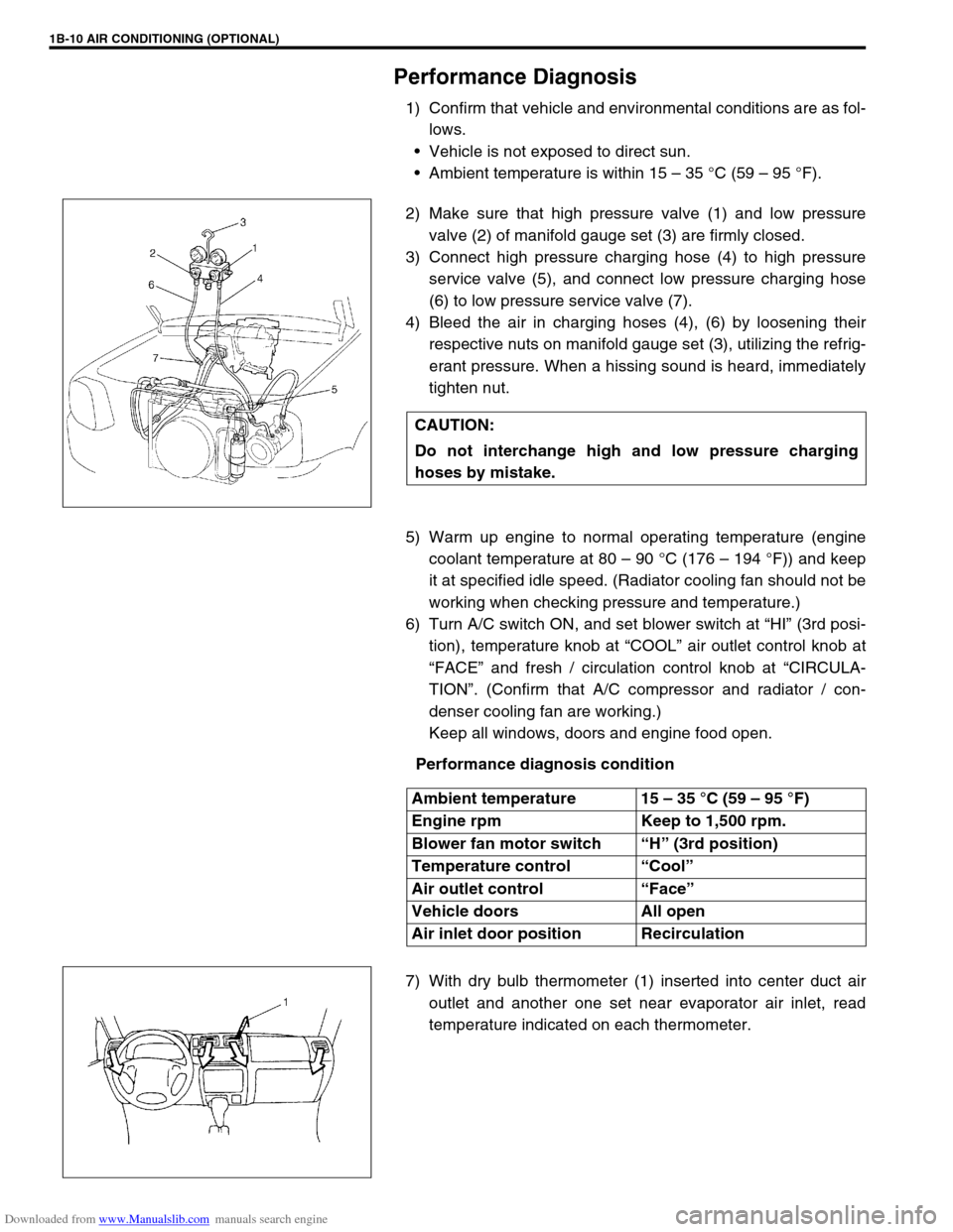
2) Make sure that high pressure valve (1) and low pressure
valve (2) of manifold gauge set (3) are firmly closed.
3) Connect high pressure charging hose (4) to high pressure
service valve (5), and connect low pressure charging hose
(6) to low pressure service valve (7).
4) Bleed the air in charging hoses (4), (6) by loosening their
respective nuts on manifold gauge set (3), utilizing the refrig-
erant pressure. When a hissing sound is heard, immediately
tighten nut.
5) Warm up engine to normal operating temperature (engine
coolant temperature at 80 – 90 °C (176 – 194 °F)) and keep
it at specified idle speed. (Radiator cooling fan should not be
working when checking pressure and temperature.)
6) Turn A/C switch ON, and set blower switch at “HI” (3rd posi-
tion), temperature knob at “COOL” air outlet control knob at
“FACE” and fresh / circulation control knob at “CIRCULA-
TION”. (Confirm that A/C compressor and radiator / con-
denser cooling fan are working.)
Keep all windows, doors and engine food open.
Performance diagnosis condition
7) With dry bulb thermometer (1) inserted into center duct air
outlet and another one set near evaporator air inlet, read
temperature indicated on each thermometer. CAUTION:
Do not interchange high and low pressure charging
hoses by mistake.
Ambient temperature 15 – 35 °C (59 – 95 °F)
Engine rpm Keep to 1,500 rpm.
Blower fan motor switch “H” (3rd position)
Temperature control “Cool”
Air outlet control “Face”
Vehicle doors All open
Air inlet door position Recirculation
Page 80 of 687

Downloaded from www.Manualslib.com manuals search engine AIR CONDITIONING (OPTIONAL) 1B-19
ECM VOLTAGE VALUES TABLE FOR RELATION OF A/C CONTROL
Terminal Wire CircuitMeasurement
groundNormal value Condition
E18-1 PCompressor
magnet clutch
outputGround to
engine (Fig B)10 – 14 voltBlower fan motor switch and A/C
switch ON with engine running
0 – 1 voltsExcept the above-mentioned condi-
tion with engine running
E18-5 Bl/BMain power sup-
ply for ECMGround to
engine (Fig B)10 – 14 voltsIgnition switch ON with engine
stopped
E18-6 Bl/BMain power sup-
ply for ECMGround to
engine (Fig B)10 – 14 voltsIgnition switch ON with engine
stopped
E18-10 Bl Main relay driveGround to
engine (Fig B)0.5 – 1.2 voltIgnition switch ON with engine
stopped
0 volts Ignition switch OFF
E18-16 G/W A/C switch inputGround to
engine (Fig B)12 – 15 voltsBlower fan motor switch or A/C switch
OFF with engine running
0 – 1 voltBlower fan motor switch and A/C
switch ON with engine running
12 – 15 voltsWithin several seconds after operate
transfer lever between 2WD and 4WD
with above condition
E18-18 P/BCompressor
cooling fan relay
outputGround to
engine (Fig B)0 – 1 voltBlower fan motor switch and A/C
switch ON or engine coolant tempera-
ture at more than 110 °C (230 °F) with
engine running.
12 – 15 voltsExcept the above-mentioned condi-
tion with engine running
E18-20 B/BlSensor ground
for A/C evapora-
torGround to
body (Fig A)–0.5 – 0 volt Engine running
E18-24 Bl/YBlower fan
speed inputGround to
engine (Fig B)0 – 1 voltBlower fan motor switch 2nd or 3rd
with engine running
4 – 7 voltsBlower fan motor switch 1st with
engine running
12 – 15 voltsBlower fan motor switch and A/C
switch OFF with engine running
E19-1 BMain ground for
ECMGround to
engine (Fig A)–0.5 – 1 volt Engine running
E19-2 B/RECM ground for
power circuitGround to
engine (Fig A)–0.5 – 1 volt Engine running
E19-3 B/RECM ground for
power circuitGround to
engine (Fig A)–0.5 – 1 volt Engine running
E19-10 B/BlSensor ground
for ECT sensorGround to
body (Fig A)–0.5 – 1 volt Engine running
Page 87 of 687

Downloaded from www.Manualslib.com manuals search engine 1B-26 AIR CONDITIONING (OPTIONAL)
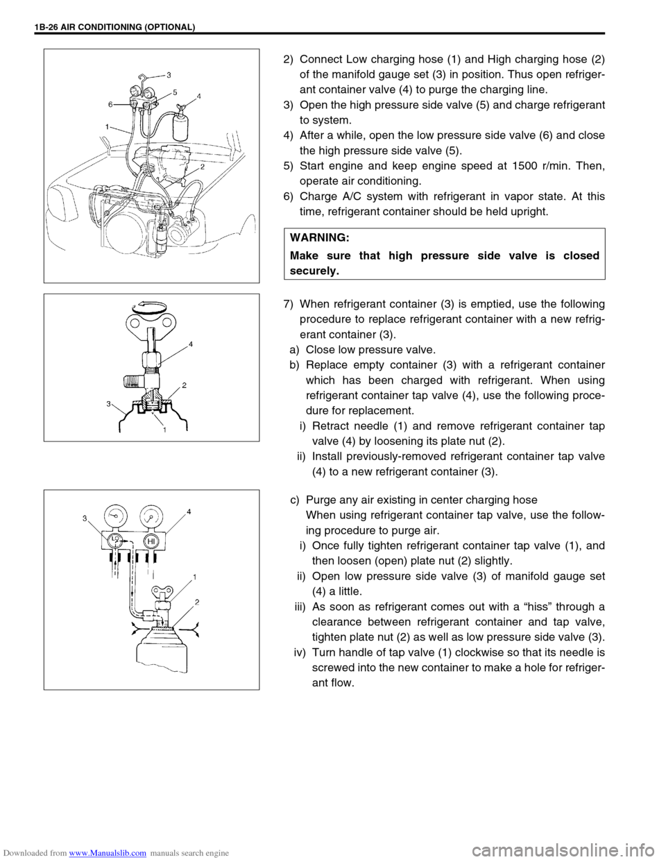
2) Connect Low charging hose (1) and High charging hose (2)
of the manifold gauge set (3) in position. Thus open refriger-
ant container valve (4) to purge the charging line.
3) Open the high pressure side valve (5) and charge refrigerant
to system.
4) After a while, open the low pressure side valve (6) and close
the high pressure side valve (5).
5) Start engine and keep engine speed at 1500 r/min. Then,
operate air conditioning.
6) Charge A/C system with refrigerant in vapor state. At this
time, refrigerant container should be held upright.
7) When refrigerant container (3) is emptied, use the following
procedure to replace refrigerant container with a new refrig-
erant container (3).
a) Close low pressure valve.
b) Replace empty container (3) with a refrigerant container
which has been charged with refrigerant. When using
refrigerant container tap valve (4), use the following proce-
dure for replacement.
i) Retract needle (1) and remove refrigerant container tap
valve (4) by loosening its plate nut (2).
ii) Install previously-removed refrigerant container tap valve
(4) to a new refrigerant container (3).
c) Purge any air existing in center charging hose
When using refrigerant container tap valve, use the follow-
ing procedure to purge air.
i) Once fully tighten refrigerant container tap valve (1), and
then loosen (open) plate nut (2) slightly.
ii) Open low pressure side valve (3) of manifold gauge set
(4) a little.
iii) As soon as refrigerant comes out with a “hiss” through a
clearance between refrigerant container and tap valve,
tighten plate nut (2) as well as low pressure side valve (3).
iv) Turn handle of tap valve (1) clockwise so that its needle is
screwed into the new container to make a hole for refriger-
ant flow. WARNING:
Make sure that high pressure side valve is closed
securely.
Page 100 of 687

Downloaded from www.Manualslib.com manuals search engine AIR CONDITIONING (OPTIONAL) 1B-39
A/C Switch
REMOVAL AND INSTALLATION
Refer to “Heater Control Lever Assembly” in Section 1A.
INSPECTION
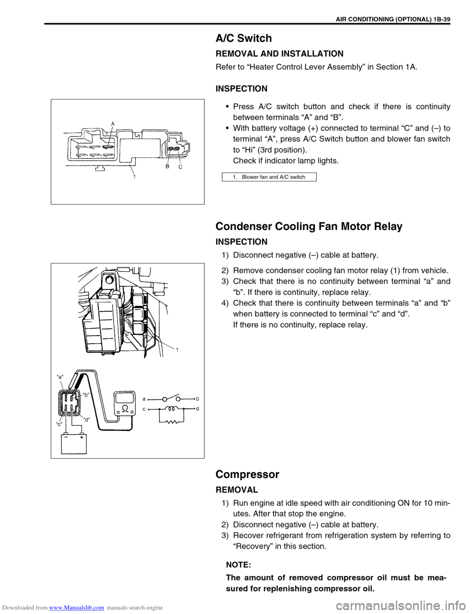
Press A/C switch button and check if there is continuity
between terminals “A” and “B”.
With battery voltage (+) connected to terminal “C” and (–) to
terminal “A”, press A/C Switch button and blower fan switch
to “Hi” (3rd position).
Check if indicator lamp lights.
Condenser Cooling Fan Motor Relay
INSPECTION
1) Disconnect negative (–) cable at battery.
2) Remove condenser cooling fan motor relay (1) from vehicle.
3) Check that there is no continuity between terminal “a” and
“b”. If there is continuity, replace relay.
4) Check that there is continuity between terminals “a” and “b”
when battery is connected to terminal “c” and “d”.
If there is no continuity, replace relay.
Compressor
REMOVAL
1) Run engine at idle speed with air conditioning ON for 10 min-
utes. After that stop the engine.
2) Disconnect negative (–) cable at battery.
3) Recover refrigerant from refrigeration system by referring to
“Recovery” in this section.
1. Blower fan and A/C switch
NOTE:
The amount of removed compressor oil must be mea-
sured for replenishing compressor oil.
Page 114 of 687

Downloaded from www.Manualslib.com manuals search engine STEERING, SUSPENSION, WHEELS AND TIRES 3-5
Tire Diagnosis
Irregular and/or Premature Wear
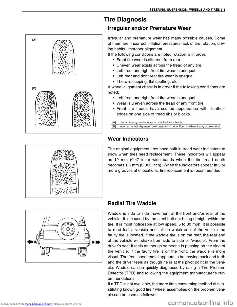
Irregular and premature wear has many possible causes. Some
of them are: incorrect inflation pressures lack of tire rotation, driv-
ing habits, improper alignment.
If the following conditions are noted rotation is in order:
Front tire wear is different from rear.
Uneven wear exists across the tread of any tire.
Left front and right front tire wear is unequal.
Left rear and right rear tire wear is unequal.
There is cupping, flat spotting, etc.
A wheel alignment check is in order if the following conditions are
noted:
Left front and right front tire wear is unequal.
Wear is uneven across the tread of any front tire.
Front tire treads have scuffed appearance with “feather”
edges on one side of tread ribs or blocks.
Wear Indicators
The original equipment tires have built-in tread wear indicators to
show when tires need replacement. These indicators will appear
as 12 mm (0.47 inch) wide bands when the tire tread depth
becomes 1.6 mm (0.063 inch). When the indicators appear in 3 or
more grooves at 6 locations, tire replacement is recommended.
Radial Tire Waddle
Waddle is side to side movement at the front and/or rear of the
vehicle. It is caused by the steel belt not being straight within the
tire. It is most noticeable at low speed, 5 to 30 mph. It is possible
to road test a vehicle and tell on which end of the vehicle the
faulty tire is located. If the waddle tire is on the rear, the rear end
of the vehicle will shake from side to side or “waddle”. From the
driver’s seat it feels as though someone is pushing on the side of
the vehicle. If the faulty tire is on the front, the waddle is more
visual. The front sheet metal appears to be moving back and forth
and the driver feels as though he is at the pivot point in the vehi-
cle. Waddle can be quickly diagnosed by using a Tire Problem
Detector (TPD) and following the equipment manufacturer’s rec-
ommendations.
If a TPD is not available, the more time consuming method of sub-
stituting known good tire / wheel assemblies on the problem vehi-
cle can be used as follows:
[A] : Hard cornering, under inflation or lack of tire rotation
[B] : Incorrect wheel alignment, tire construction not uniform or wheel heavy acceleration