electrical system SUZUKI JIMNY 2005 3.G Service Workshop Manual
[x] Cancel search | Manufacturer: SUZUKI, Model Year: 2005, Model line: JIMNY, Model: SUZUKI JIMNY 2005 3.GPages: 687, PDF Size: 13.38 MB
Page 4 of 687
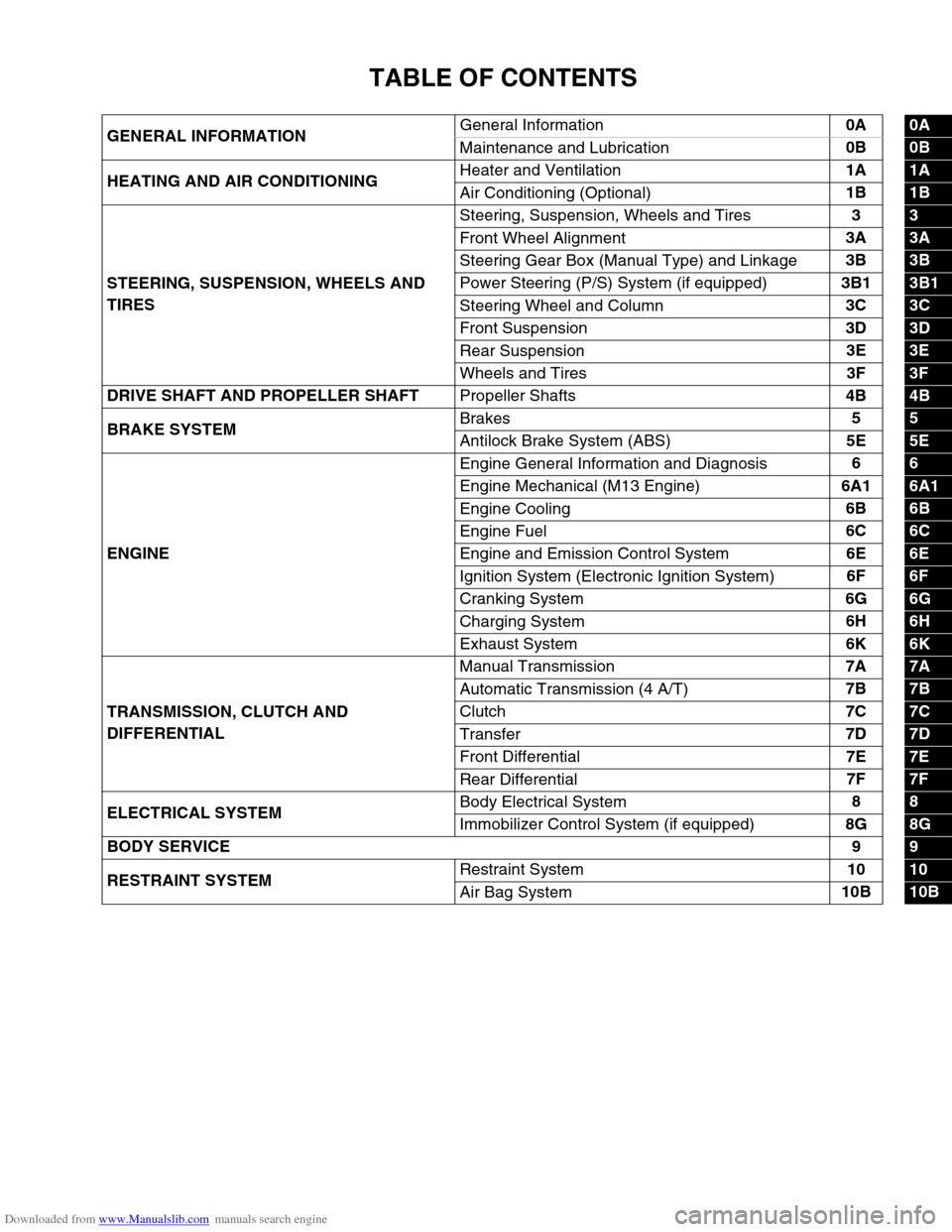
Downloaded from www.Manualslib.com manuals search engine TABLE OF CONTENTS
GENERAL INFORMATIONGeneral Information0A0A
Maintenance and Lubrication0B
0B
HEATING AND AIR CONDITIONINGHeater and Ventilation1A
1A
Air Conditioning (Optional)1B
1B
STEERING, SUSPENSION, WHEELS AND
TIRESSteering, Suspension, Wheels and Tires3
3
Front Wheel Alignment3A
3A
Steering Gear Box (Manual Type) and Linkage3B
3B
Power Steering (P/S) System (if equipped)3B1
3B1
Steering Wheel and Column3C
3C
Front Suspension3D
3D
Rear Suspension3E
3E
Wheels and Tires3F
3F
DRIVE SHAFT AND PROPELLER SHAFT
Propeller Shafts4B
4B
BRAKE SYSTEMBrakes5
5
Antilock Brake System (ABS)5E
5E
ENGINEEngine General Information and Diagnosis6
6
Engine Mechanical (M13 Engine)6A1
6A1
Engine Cooling6B
6B
Engine Fuel6C
6C
Engine and Emission Control System6E
6E
Ignition System (Electronic Ignition System)6F
6F
Cranking System6G
6G
Charging System6H
6H
Exhaust System6K
6K
TRANSMISSION, CLUTCH AND
DIFFERENTIALManual Transmission7A
7A
Automatic Transmission (4 A/T)7B
7B
Clutch7C
7C
Transfer7D
7D
Front Differential7E
7E
Rear Differential7F
7F
ELECTRICAL SYSTEMBody Electrical System8
8
Immobilizer Control System (if equipped)8G
8G
BODY SERVICE9
9
RESTRAINT SYSTEMRestraint System10
10
Air Bag System10B
10B
Page 6 of 687
Downloaded from www.Manualslib.com manuals search engine GENERAL INFORMATION 0A-1
0A
6F2
6G
6H
6K
7A
7A1
7B1
7C1
7D
7E
7F
8A
8B
8C
8D
8E
9
10
10A
10B
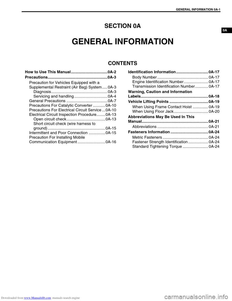
SECTION 0A
GENERAL INFORMATION
CONTENTS
How to Use This Manual .................................0A-2
Precautions......................................................0A-3
Precaution for Vehicles Equipped with a
Supplemental Restraint (Air Bag) System ..... 0A-3
Diagnosis................................................... 0A-3
Servicing and handling .............................. 0A-4
General Precautions ..................................... 0A-7
Precautions For Catalytic Converter ........... 0A-10
Precautions For Electrical Circuit Service ... 0A-10
Electrical Circuit Inspection Procedure........ 0A-13
Open circuit check ................................... 0A-13
Short circuit check (wire harness to
ground) .................................................... 0A-15
Intermittent and Poor Connection ............... 0A-15
Precaution For Installing Mobile
Communication Equipment ......................... 0A-16Identification Information ............................. 0A-17
Body Number .............................................. 0A-17
Engine Identification Number ...................... 0A-17
Transmission Identification Number............ 0A-17
Warning, Caution and Information
Labels............................................................. 0A-18
Vehicle Lifting Points ................................... 0A-19
When Using Frame Contact Hoist .............. 0A-19
When Using Floor Jack ............................... 0A-20
Abbreviations May Be Used In This
Manual............................................................ 0A-21
Abbreviations .............................................. 0A-21
Fasteners Information .................................. 0A-24
Metric Fasteners ......................................... 0A-24
Fastener Strength Identification .................. 0A-24
Standard Tightening Torque ....................... 0A-24
Page 8 of 687
Downloaded from www.Manualslib.com manuals search engine GENERAL INFORMATION 0A-3
Precautions
Precaution for Vehicles Equipped with a Sup-
plemental Restraint (Air Bag) System
Diagnosis
When troubleshooting air bag system, be sure to follow “Air
Bag Diagnostic System Check” in Section 10B. Bypassing
these procedures may result in extended diagnostic time,
incorrect diagnosis, and incorrect parts replacement.
Never use electrical test equipment other than that specified
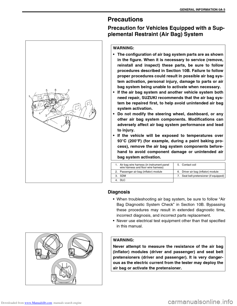
in this manual. WARNING:
The configuration of air bag system parts are as shown
in the figure. When it is necessary to service (remove,
reinstall and inspect) these parts, be sure to follow
procedures described in Section 10B. Failure to follow
proper procedures could result in possible air bag sys-
tem activation, personal injury, damage to parts or air
bag system being unable to activate when necessary.
If the air bag system and another vehicle system both
need repair, SUZUKI recommends that the air bag sys-
tem be repaired first, to help avoid unintended air bag
system activation.
Do not modify the steering wheel, dashboard, or any
other air bag system components. Modifications can
adversely affect air bag system performance and lead
to injury.
If the vehicle will be exposed to temperatures over
93°C (200°F) (for example, during a paint baking pro-
cess), remove the air bag system components before-
hand to avoid component damage or unintended air
bag system activation.
1. Air bag wire harness (in instrument panel
wire harness and floor wire harness)5. Contact coil
2. Passenger air bag (inflator) module 6. Driver air bag (inflator) module
3. SDM 7. Seat belt pretensioner (if equipped)
4. DLC
WARNING:
Never attempt to measure the resistance of the air bag
(inflator) modules (driver and passenger) and seat belt
pretensioners (driver and passenger). It is very danger-
ous as the electric current from the tester may deploy the
air bag or activate the pretensioner.
Page 12 of 687
Downloaded from www.Manualslib.com manuals search engine GENERAL INFORMATION 0A-7
General Precautions
The WARNING and CAUTION below describe some general precautions that you should observe when servic-
ing a vehicle. These general precautions apply to many of the service procedures described in this manual, and
they will not necessarily be repeated with each procedure to which they apply.
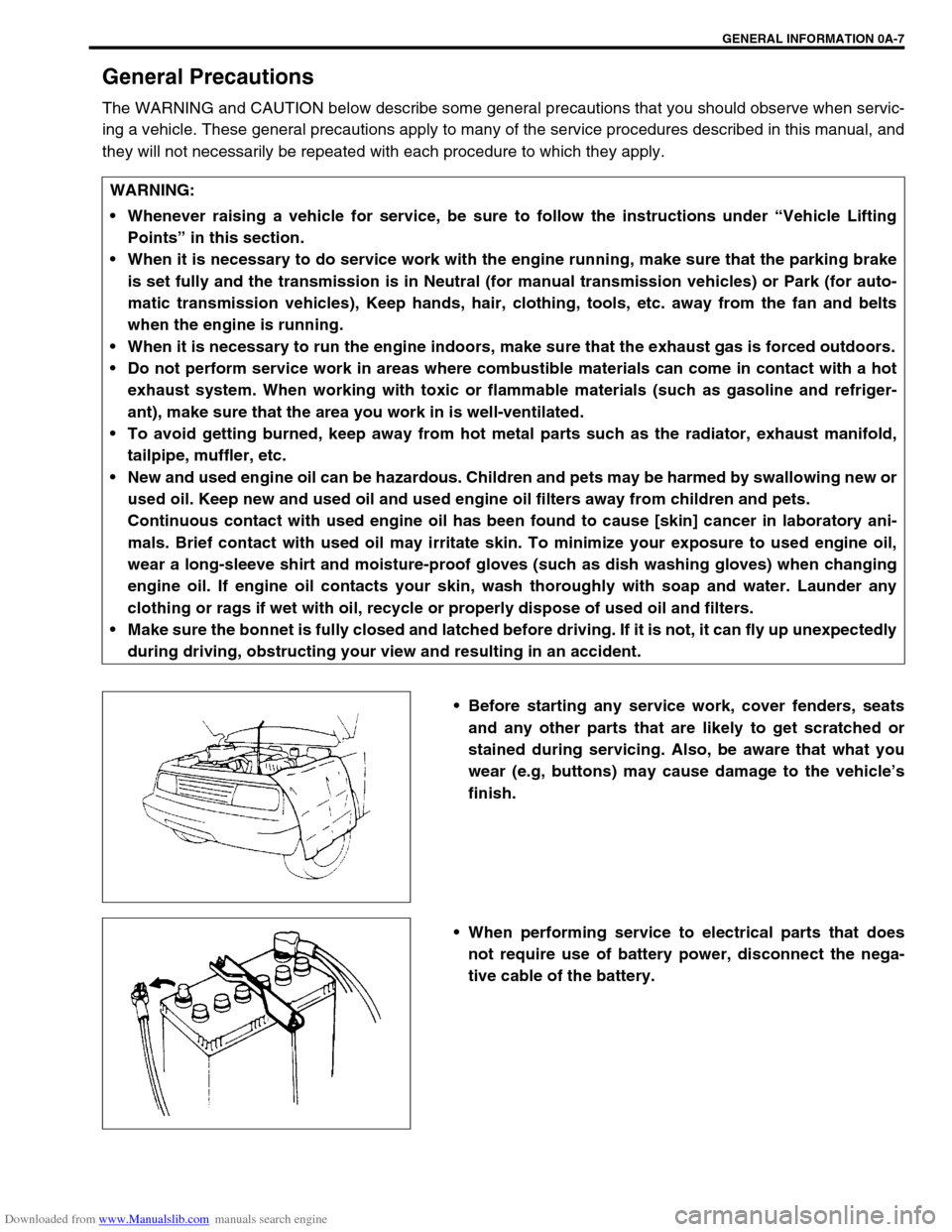
Before starting any service work, cover fenders, seats
and any other parts that are likely to get scratched or
stained during servicing. Also, be aware that what you
wear (e.g, buttons) may cause damage to the vehicle’s
finish.
When performing service to electrical parts that does
not require use of battery power, disconnect the nega-
tive cable of the battery. WARNING:
Whenever raising a vehicle for service, be sure to follow the instructions under “Vehicle Lifting
Points” in this section.
When it is necessary to do service work with the engine running, make sure that the parking brake
is set fully and the transmission is in Neutral (for manual transmission vehicles) or Park (for auto-
matic transmission vehicles), Keep hands, hair, clothing, tools, etc. away from the fan and belts
when the engine is running.
When it is necessary to run the engine indoors, make sure that the exhaust gas is forced outdoors.
Do not perform service work in areas where combustible materials can come in contact with a hot
exhaust system. When working with toxic or flammable materials (such as gasoline and refriger-
ant), make sure that the area you work in is well-ventilated.
To avoid getting burned, keep away from hot metal parts such as the radiator, exhaust manifold,
tailpipe, muffler, etc.
New and used engine oil can be hazardous. Children and pets may be harmed by swallowing new or
used oil. Keep new and used oil and used engine oil filters away from children and pets.
Continuous contact with used engine oil has been found to cause [skin] cancer in laboratory ani-
mals. Brief contact with used oil may irritate skin. To minimize your exposure to used engine oil,
wear a long-sleeve shirt and moisture-proof gloves (such as dish washing gloves) when changing
engine oil. If engine oil contacts your skin, wash thoroughly with soap and water. Launder any
clothing or rags if wet with oil, recycle or properly dispose of used oil and filters.
Make sure the bonnet is fully closed and latched before driving. If it is not, it can fly up unexpectedly
during driving, obstructing your view and resulting in an accident.
Page 14 of 687
Downloaded from www.Manualslib.com manuals search engine GENERAL INFORMATION 0A-9
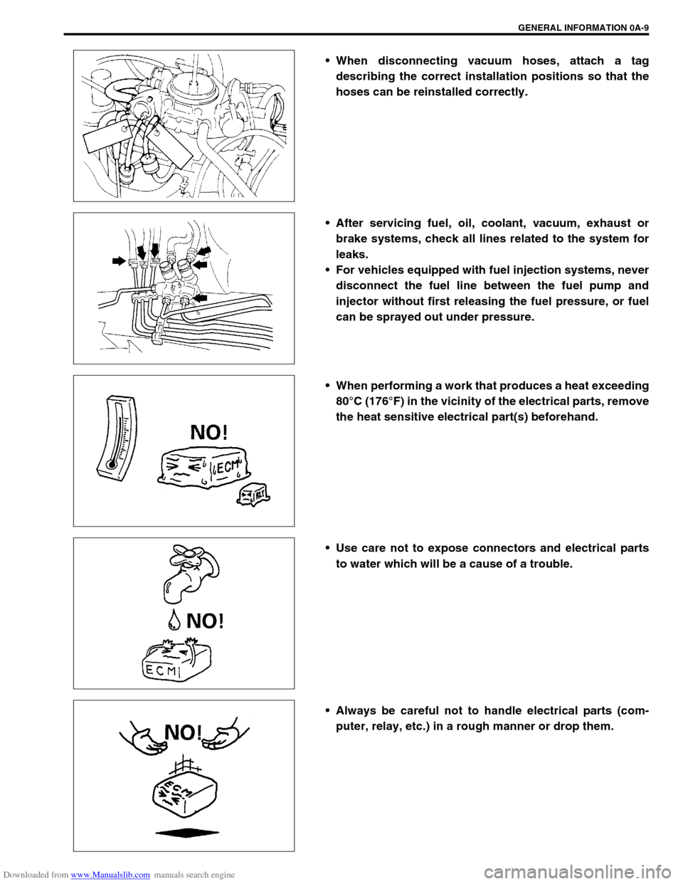
When disconnecting vacuum hoses, attach a tag
describing the correct installation positions so that the
hoses can be reinstalled correctly.
After servicing fuel, oil, coolant, vacuum, exhaust or
brake systems, check all lines related to the system for
leaks.
For vehicles equipped with fuel injection systems, never
disconnect the fuel line between the fuel pump and
injector without first releasing the fuel pressure, or fuel
can be sprayed out under pressure.
When performing a work that produces a heat exceeding
80°C (176°F) in the vicinity of the electrical parts, remove
the heat sensitive electrical part(s) beforehand.
Use care not to expose connectors and electrical parts
to water which will be a cause of a trouble.
Always be careful not to handle electrical parts (com-
puter, relay, etc.) in a rough manner or drop them.
Page 17 of 687
Downloaded from www.Manualslib.com manuals search engine 0A-12 GENERAL INFORMATION
Never connect any tester (voltmeter, ohmmeter, or what-
ever) to electronic control unit when its coupler is dis-
connected. Attempt to do it may cause damage to it.
Never connect an ohmmeter to electronic control unit
with its coupler connected to it. Attempt to do it may
cause damage to electronic control unit and sensors.
Be sure to use a specified voltmeter / ohmmeter. Other-
wise, accurate measurements may not be obtained or
personal injury may result.
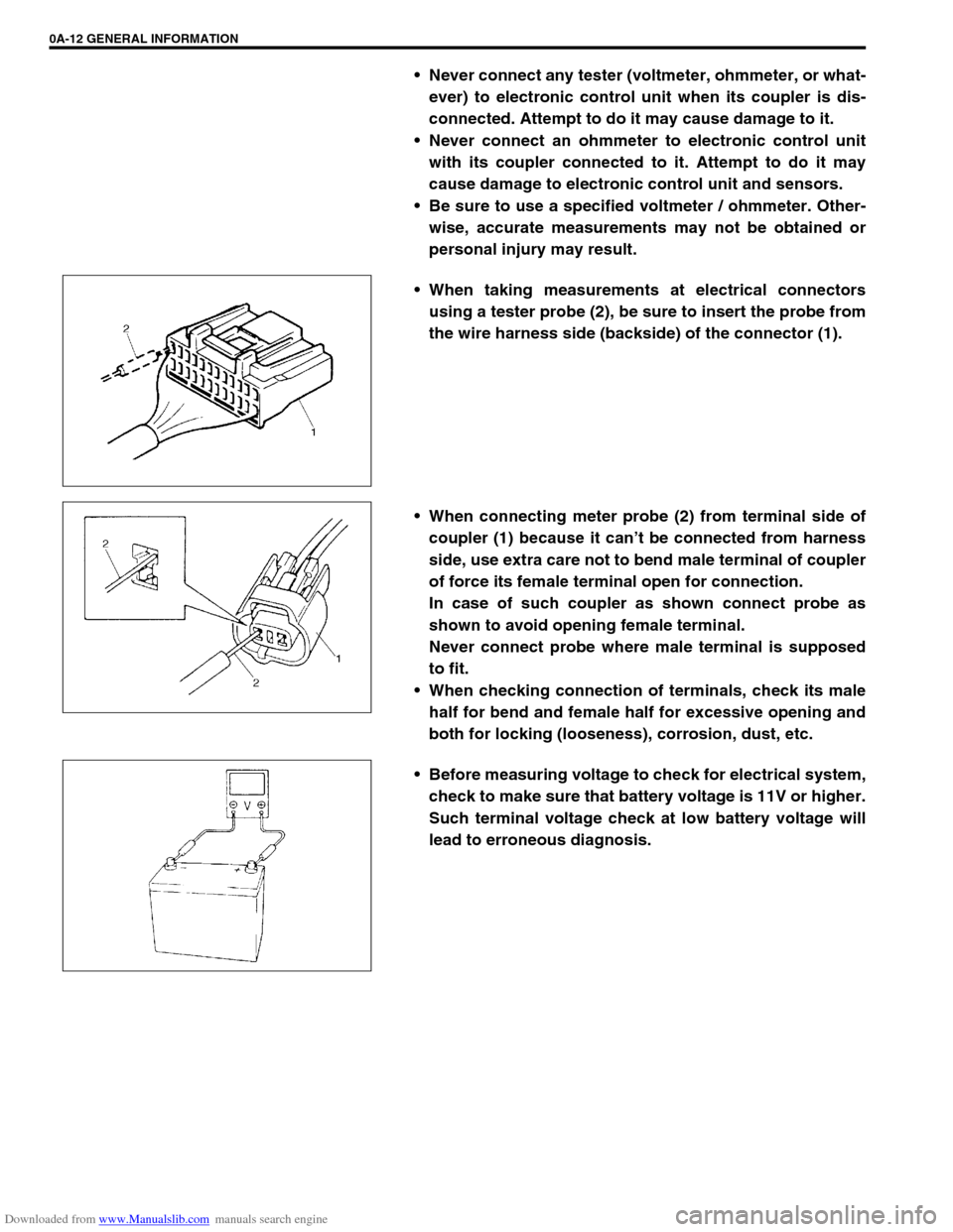
When taking measurements at electrical connectors
using a tester probe (2), be sure to insert the probe from
the wire harness side (backside) of the connector (1).
When connecting meter probe (2) from terminal side of
coupler (1) because it can’t be connected from harness
side, use extra care not to bend male terminal of coupler
of force its female terminal open for connection.
In case of such coupler as shown connect probe as
shown to avoid opening female terminal.
Never connect probe where male terminal is supposed
to fit.
When checking connection of terminals, check its male
half for bend and female half for excessive opening and
both for locking (looseness), corrosion, dust, etc.
Before measuring voltage to check for electrical system,
check to make sure that battery voltage is 11V or higher.
Such terminal voltage check at low battery voltage will
lead to erroneous diagnosis.
Page 18 of 687
Downloaded from www.Manualslib.com manuals search engine GENERAL INFORMATION 0A-13
Electrical Circuit Inspection Procedure
While there are various electrical circuit inspection methods,
described here is a general method to check its open and short
circuit by using an ohmmeter and a voltmeter.
Open circuit check
Possible causes for the open circuit are as follows. As the cause
is in the connector or terminal in many cases, they need to be
checked particularly carefully.
Loose connection of connector
Poor contact of terminal (due to dirt, corrosion or rust on it,
poor contact tension, entry of foreign object etc.)
Wire harness being open
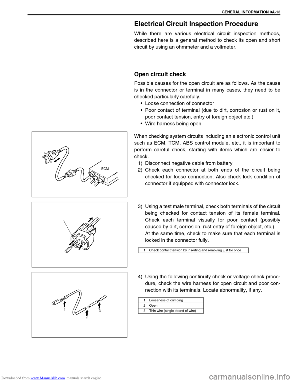
When checking system circuits including an electronic control unit
such as ECM, TCM, ABS control module, etc., it is important to
perform careful check, starting with items which are easier to
check.
1) Disconnect negative cable from battery
2) Check each connector at both ends of the circuit being
checked for loose connection. Also check lock condition of
connector if equipped with connector lock.
3) Using a test male terminal, check both terminals of the circuit
being checked for contact tension of its female terminal.
Check each terminal visually for poor contact (possibly
caused by dirt, corrosion, rust entry of foreign object, etc.).
At the same time, check to make sure that each terminal is
locked in the connector fully.
4) Using the following continuity check or voltage check proce-
dure, check the wire harness for open circuit and poor con-
nection with its terminals. Locate abnormality, if any.
1. Check contact tension by inserting and removing just for once
1. Looseness of crimping
2. Open
3. Thin wire (single strand of wire)
Page 181 of 687

Downloaded from www.Manualslib.com manuals search engine 3D-8 FRONT SUSPENSION
Diagnosis
Diagnosis Table
For description not found in the table below, refer to “Diagnosis Table” in Section 3.
4WD CONTROL SYSTEM
4WD CONTROL SYSTEM DIAGNOSTIC FLOW TABLE
Before performing the trouble diagnosis, check that the air locking hub assemblies are in good condition and
there is no air leakage from vacuum hoses and vacuum pipe. Refer to “4WD Control System Check” in this sec-
tion for air leakage.
[NOTES ON SYSTEM CIRCUIT INSPECTION]
Be sure to read “Precautions for Electrical Circuit Service” in Section 0A before circuit inspection and
observe what is written there.
For system circuit, refer to the figure of “System Circuit” in this section. Condition Possible Cause Correction
4WD Indicator light
flashingHub locking procedure error
Defective VSV2
Defective vacuum switch
Defective check valve or vacuum tank
Air leak from vacuum circuit
Clogged vacuum hose or pipe
Faulty 4WD controllerShift transfer shift control lever
2WD → 4WD once again
Replace
Replace
Replace
Check and repair
Replace
Check and replace
2WD/4WD switching
errorDefective air locking hub assembly
Abnormality in 4WD control system
Air leakage from vacuum circuit
Clogged vacuum hose or pipe
Defective check valve or vacuum tankReplace
Inspect referring to “4WD Control
System Diagnostic Flow Table”
Check and replace
Replace
Replace
Step Action Yes No
1 Check ground circuit.
1) Disconnect coupler from 4WD controller
with ignition switch OFF.
2) Check for proper connection to 4WD con-
troller at all terminals.
3) If OK, check continuity between A5 terminal
and body ground.
Is there continuity between A5 terminal and
body ground?Go to Step 2.“B” wire is open.
2 Check power circuit.
1) Disconnect coupler from 4WD controller.
2) Turn ignition switch ON.
3) Check voltage between A10 terminal and
ground.
Is it 10 – 14 V?Go to Step 3.“Y/R” circuit is open or
short.
Page 360 of 687
Downloaded from www.Manualslib.com manuals search engine ENGINE GENERAL INFORMATION AND DIAGNOSIS 6-3
General Information
Statement on Cleanliness and Care
An automobile engine is a combination of many machined, honed, polished and lapped surfaces with tolerances
that are measured in the thousands of an millimeter (ten thousands of an inch).
Accordingly, when any internal engine parts are serviced, care and cleanliness are important.
Throughout this section, it should be understood that proper cleaning and protection of machined surfaces and
friction areas is part of the repair procedure. This is considered standard shop practice even if not specifically
stated.
A liberal coating of engine oil should be applied to friction areas during assembly to protect and lubricate the
surfaces on initial operation.
Whenever valve train components, pistons, piston rings, connecting rods, rod bearings, and crankshaft jour-
nal bearings are removed for service, they should be retained in order.
At the time of installation, they should be installed in the same locations and with the same mating surfaces
as when removed.
Battery cables should be disconnected before any major work is performed on the engine.
Failure to disconnect cables may result in damage to wire harness or other electrical parts.
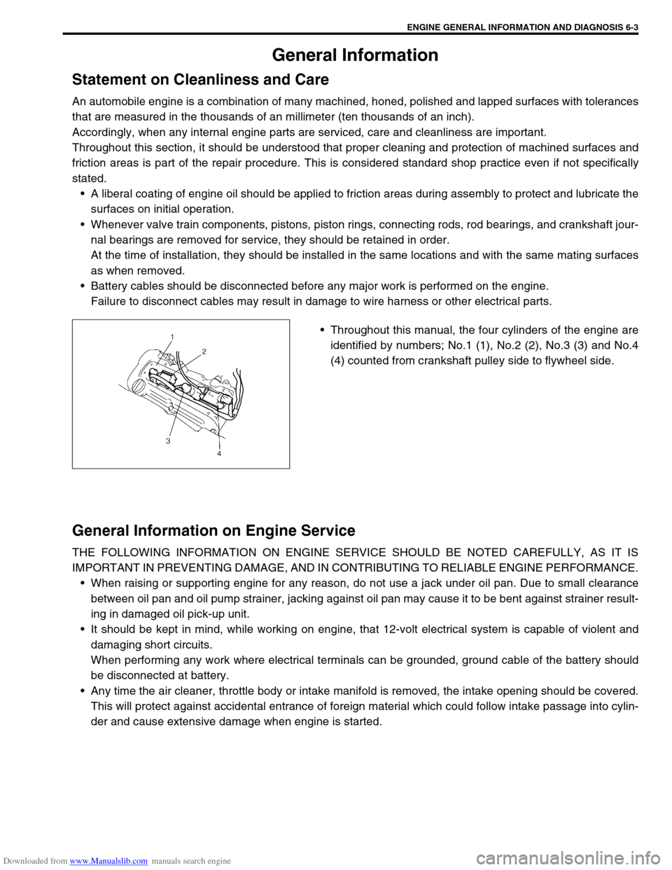
Throughout this manual, the four cylinders of the engine are
identified by numbers; No.1 (1), No.2 (2), No.3 (3) and No.4
(4) counted from crankshaft pulley side to flywheel side.
General Information on Engine Service
THE FOLLOWING INFORMATION ON ENGINE SERVICE SHOULD BE NOTED CAREFULLY, AS IT IS
IMPORTANT IN PREVENTING DAMAGE, AND IN CONTRIBUTING TO RELIABLE ENGINE PERFORMANCE.
When raising or supporting engine for any reason, do not use a jack under oil pan. Due to small clearance
between oil pan and oil pump strainer, jacking against oil pan may cause it to be bent against strainer result-
ing in damaged oil pick-up unit.
It should be kept in mind, while working on engine, that 12-volt electrical system is capable of violent and
damaging short circuits.
When performing any work where electrical terminals can be grounded, ground cable of the battery should
be disconnected at battery.
Any time the air cleaner, throttle body or intake manifold is removed, the intake opening should be covered.
This will protect against accidental entrance of foreign material which could follow intake passage into cylin-
der and cause extensive damage when engine is started.
Page 367 of 687

Downloaded from www.Manualslib.com manuals search engine 6-10 ENGINE GENERAL INFORMATION AND DIAGNOSIS
Precaution in Diagnosing Trouble
Don’t disconnect couplers from ECM, battery cable at battery, ECM ground wire harness from engine or
main fuse before confirming diagnostic information (DTC, freeze frame data, etc.) stored in ECM memory.
Such disconnection will erase memorized information in ECM memory.
Diagnostic information stored in ECM memory can be cleared as well as checked by using SUZUKI scan
tool or generic scan tool. Before using scan tool, read its Operator’s (Instruction) Manual carefully to have
good understanding as to what functions are available and how to use it.
Priorities for diagnosing troubles (Vehicle with Immobilizer indicator lamp).
If multiple diagnostic trouble codes (DTCs) are stored, proceed to the flow table of the DTC which has
detected earliest in the order and follow the instruction in that table.
If no instructions are given, troubleshoot diagnostic trouble codes according to the following priorities.
–Diagnostic trouble codes (DTCs) other than DTC P0171/P0172 (Fuel system too lean / too rich), DTC
P0300/P0301/P0302/P0303/P0304 (Misfire detected) and DTC P0400 (EGR flow malfunction)
–DTC P0171/P0172 (Fuel system too lean / too rich) and DTC P0400 (EGR flow malfunction)
–DTC P0300/P0301/P0302/P0303/P0304 (Misfire detected)
Be sure to read “Precautions for Electrical Circuit Service” in Section 0A before inspection and observe what
is written there.
ECM Replacement
When substituting a known-good ECM, check for following conditions. Neglecting this check may cause
damage to a known-good ECM.
–Resistance value of all relays, actuators is as specified respectively.
–MAP sensor and TP sensor are in good condition and none of power circuits of these sensors is shorted
to ground.AMBIENT TEMPERATURE TIME TO CUT POWER TO
ECM
Over 0 °C (32 °F) 60 sec. or longer
Under 0 °C (32 °F)Not specifiable.
Select a place with higher than
0 °C (32 °F) temperature.