recommended oil SUZUKI JIMNY 2005 3.G Service Workshop Manual
[x] Cancel search | Manufacturer: SUZUKI, Model Year: 2005, Model line: JIMNY, Model: SUZUKI JIMNY 2005 3.GPages: 687, PDF Size: 13.38 MB
Page 32 of 687
Downloaded from www.Manualslib.com manuals search engine MAINTENANCE AND LUBRICATION 0B-1
0A 6F1
0B
0B
6G
1A 6H
1B 6K
37A
3A 7A1
3B1 7B1
3C1 7C1
3D 7D
3E 7E
3F 7F
4A2 8A
4B 8B
8C
58D
5A 8E
5B
5C 9
5E
5E1 10
10A
610B
6-1
6A1
6A2
6A4
6B
6C
6E1
6E2
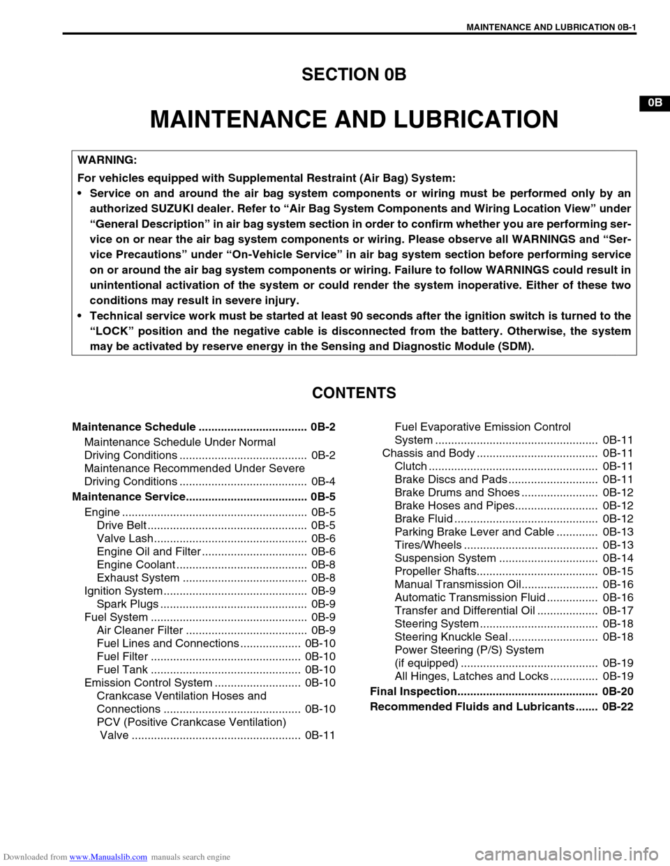
SECTION 0B
MAINTENANCE AND LUBRICATION
CONTENTS
Maintenance Schedule .................................. 0B-2
Maintenance Schedule Under Normal
Driving Conditions ........................................ 0B-2
Maintenance Recommended Under Severe
Driving Conditions ........................................ 0B-4
Maintenance Service...................................... 0B-5
Engine .......................................................... 0B-5
Drive Belt .................................................. 0B-5
Valve Lash................................................ 0B-6
Engine Oil and Filter ................................. 0B-6
Engine Coolant ......................................... 0B-8
Exhaust System ....................................... 0B-8
Ignition System ............................................. 0B-9
Spark Plugs .............................................. 0B-9
Fuel System ................................................. 0B-9
Air Cleaner Filter ...................................... 0B-9
Fuel Lines and Connections ................... 0B-10
Fuel Filter ............................................... 0B-10
Fuel Tank ............................................... 0B-10
Emission Control System ........................... 0B-10
Crankcase Ventilation Hoses and
Connections ........................................... 0B-10
PCV (Positive Crankcase Ventilation)
Valve ..................................................... 0B-11Fuel Evaporative Emission Control
System ................................................... 0B-11
Chassis and Body ...................................... 0B-11
Clutch ..................................................... 0B-11
Brake Discs and Pads ............................ 0B-11
Brake Drums and Shoes ........................ 0B-12
Brake Hoses and Pipes.......................... 0B-12
Brake Fluid ............................................. 0B-12
Parking Brake Lever and Cable ............. 0B-13
Tires/Wheels .......................................... 0B-13
Suspension System ............................... 0B-14
Propeller Shafts...................................... 0B-15
Manual Transmission Oil........................ 0B-16
Automatic Transmission Fluid ................ 0B-16
Transfer and Differential Oil ................... 0B-17
Steering System ..................................... 0B-18
Steering Knuckle Seal ............................ 0B-18
Power Steering (P/S) System
(if equipped) ........................................... 0B-19
All Hinges, Latches and Locks ............... 0B-19
Final Inspection............................................ 0B-20
Recommended Fluids and Lubricants ....... 0B-22
WARNING:
For vehicles equipped with Supplemental Restraint (Air Bag) System:
Service on and around the air bag system components or wiring must be performed only by an
authorized SUZUKI dealer. Refer to “Air Bag System Components and Wiring Location View” under
“General Description” in air bag system section in order to confirm whether you are performing ser-
vice on or near the air bag system components or wiring. Please observe all WARNINGS and “Ser-
vice Precautions” under “On-Vehicle Service” in air bag system section before performing service
on or around the air bag system components or wiring. Failure to follow WARNINGS could result in
unintentional activation of the system or could render the system inoperative. Either of these two
conditions may result in severe injury.
Technical service work must be started at least 90 seconds after the ignition switch is turned to the
“LOCK” position and the negative cable is disconnected from the battery. Otherwise, the system
may be activated by reserve energy in the Sensing and Diagnostic Module (SDM).
Page 33 of 687

Downloaded from www.Manualslib.com manuals search engine 0B-2 MAINTENANCE AND LUBRICATION
Maintenance Schedule
Maintenance Schedule Under Normal Driving Conditions
NOTE:
This interval should be judged by odometer reading or months, whichever comes first.
This table includes service as scheduled up to 90,000 km (54,000 miles) mileage. Beyond 90,000 km
(54,000 miles), carry out the same services at the same intervals respectively.
IntervalKm (x 1,000) 15 30 45 60 75 90
Miles (x 1,000) 9 1827364554
Months 12 24 36 48 60 72
ENGINE
Drive belt V-belt I R I R I R
V-rib belt (Flat type)––I––R
Valve lash (clearance) –I–I–I
Engine oil and oil filter R R R R R R
Engine coolant––R––R
Exhaust system–I–I–I
IGNITION SYSTEM
✱Spark plugs When
unleaded
fuel is usedVehicle without
HO2SNickel spark
plug–R–R–R
Iridium spark
plug––R––R
Vehicle with
HO2SNickel spark
plug––R––R
Iridium spark
plug–––R––
When leaded fuel is used, refer to “Maintenance Recommended Under Severe Driving Condi-
tions” in this section.
FUEL SYSTEM
Air cleaner filter I I R I I R
Fuel lines and connections–I–I–I
Fuel filter Replace every 210,000 km (126,000 miles).
Fuel tank––I––I
EMISSION CONTROL SYSTEM
Crankcase ventilation hoses and connections
(Vehicle without HO2S)––I––I
✱PCV valve Vehicle without HO2S––I––I
Vehicle with HO2S–––––I
✱Fuel evaporative emission
control systemVehicle without HO2S–I–I–I
Vehicle with HO2S–––––I
NOTE:
“R”: Replace or change
“I”: Inspect and correct, replace or lubricate if necessary
For Sweden, items with
✱
✱✱ ✱ (asterisk) should be performed by odometer reading only.
For spark plugs, replace every 50,000 km if the local law requires.
Nickel spark plug: BKR6E-11 (NGK) or K20PR-U11 (DENSO)
Iridium spark plug: IFR5E11 (NGK) or SK16PR-A11 (DENSO)
Page 35 of 687

Downloaded from www.Manualslib.com manuals search engine 0B-4 MAINTENANCE AND LUBRICATION
Maintenance Recommended Under Severe Driving Conditions
If the vehicle is usually used under the conditions corresponding to any severe condition code given below, it is
recommended that applicable maintenance operation be performed at the particular interval as shown in the fol-
lowing table.
Severe condition code
A : Repeated short trips
B : Driving on rough and/or muddy roads
C : Driving on dusty roads
D : Driving in extremely cold weather and/or salted roads
E : Repeated short trips in extremely cold weather
F : Leaded fuel use
G : – – – – –
H : Trailer towing (if admitted)
Severe
Condition CodeMaintenanceMaintenance
OperationMaintenance Interval
– B C D – – – –Drive belt (V-rib belt)IEvery 15,000 km
(9,000 miles) or 12 months
REvery 45,000 km
(27,000 miles) or 36 months
A – C D E F – H Engine oil and oil filter R Every 5,000 km (3,000 miles) or 4 months
– B – – – – – –Exhaust pipe mountings IEvery 15,000 km
(9,000 miles) or 12 months
– – C – – – – –Air cleaner filter ✱1I Every 2,500 km (1,500 miles)
REvery 30,000 km
(18,000 miles) or 24 months
A B C – E F – H Spark plugsNickel spark plug R Every 10,000 km (6,000 miles) or 8 months
Iridium spark plug
REvery 30,000 km
(18,000 miles) or 24 months
– B C D – – – H Wheel bearing IEvery 15,000 km
(9,000 miles) or 12 months
– B – – – – – –Suspension bolts and nuts TEvery 15,000 km
(9,000 miles) or 12 months
– B – D E – – H Propeller shafts IEvery 15,000 km
(9,000 miles) or 12 months
– B – – E – – HManual transmission,
transfer and differential oilRFirst time only:
15,000 km (9,000 miles) or 12 months
Second time and after: Every 30,000 km
(18,000 miles) or 24 months reckoning from
0 km (0 mile) or 0 month
– B – – E – – H Automatic transmission fluid REvery 30,000 km
(18,000 miles) or 24 months
– B C D – – – –Steering knuckle seal IEvery 15,000 km
(9,000 miles) or 12 months
NOTE:
“I”: Inspect and correct, replace or lubricate if necessary
“R”: Replace or change
“T”: Tighten to the specified torque
✱
✱✱ ✱1: Inspect or replace more frequently if necessary
Page 39 of 687
Downloaded from www.Manualslib.com manuals search engine 0B-8 MAINTENANCE AND LUBRICATION
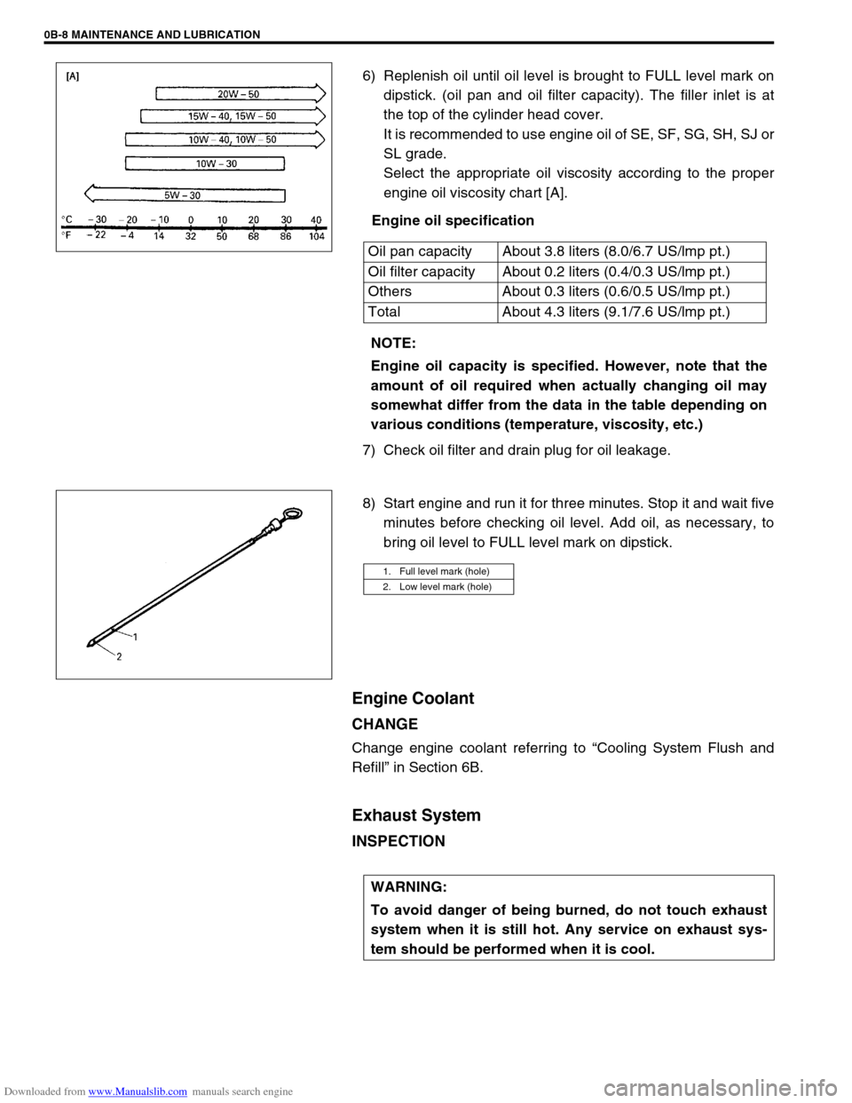
6) Replenish oil until oil level is brought to FULL level mark on
dipstick. (oil pan and oil filter capacity). The filler inlet is at
the top of the cylinder head cover.
It is recommended to use engine oil of SE, SF, SG, SH, SJ or
SL grade.
Select the appropriate oil viscosity according to the proper
engine oil viscosity chart [A].
Engine oil specification
7) Check oil filter and drain plug for oil leakage.
8) Start engine and run it for three minutes. Stop it and wait five
minutes before checking oil level. Add oil, as necessary, to
bring oil level to FULL level mark on dipstick.
Engine Coolant
CHANGE
Change engine coolant referring to “Cooling System Flush and
Refill” in Section 6B.
Exhaust System
INSPECTION
Oil pan capacity About 3.8 liters (8.0/6.7 US/lmp pt.)
Oil filter capacity About 0.2 liters (0.4/0.3 US/lmp pt.)
Others About 0.3 liters (0.6/0.5 US/lmp pt.)
Total About 4.3 liters (9.1/7.6 US/lmp pt.)
NOTE:
Engine oil capacity is specified. However, note that the
amount of oil required when actually changing oil may
somewhat differ from the data in the table depending on
various conditions (temperature, viscosity, etc.)
1. Full level mark (hole)
2. Low level mark (hole)
WARNING:
To avoid danger of being burned, do not touch exhaust
system when it is still hot. Any service on exhaust sys-
tem should be performed when it is cool.
Page 53 of 687

Downloaded from www.Manualslib.com manuals search engine 0B-22 MAINTENANCE AND LUBRICATION
Recommended Fluids and Lubricants
Engine oilSE, SF, SG, SH, SJ or SL
(Refer to “Engine Oil and Oil Filter” in this section for engine oil viscos-
ity.)
Engine coolant
(Ethylene glycol base coolant)“Antifreeze/Anticorrosion coolant”
Brake fluid DOT 3
Manual transmission oil Refer to “Maintenance Service” in Section 7A.
Transfer oil Refer to “Oil Change” in Section 7D.
Differential oil (front & rear) Refer to “Oil Change” in Section 7E and 7F.
Automatic transmission fluid
An equivalent of DEXRON
®-IIE or DEXRON®-III
Power steering fluid
An equivalent of DEXRON
®-II, DEXRON®-IIE or DEXRON®-III
Clutch linkage pivot points
Water resistance chassis grease
(SUZUKI SUPER GREASE A 99000-25010)
Steering knuckle seal
Door hinges
Engine oil or water resistance chassis grease
Hood latch assembly
Key lock cylinder Spray lubricant
Page 108 of 687
Downloaded from www.Manualslib.com manuals search engine AIR CONDITIONING (OPTIONAL) 1B-47
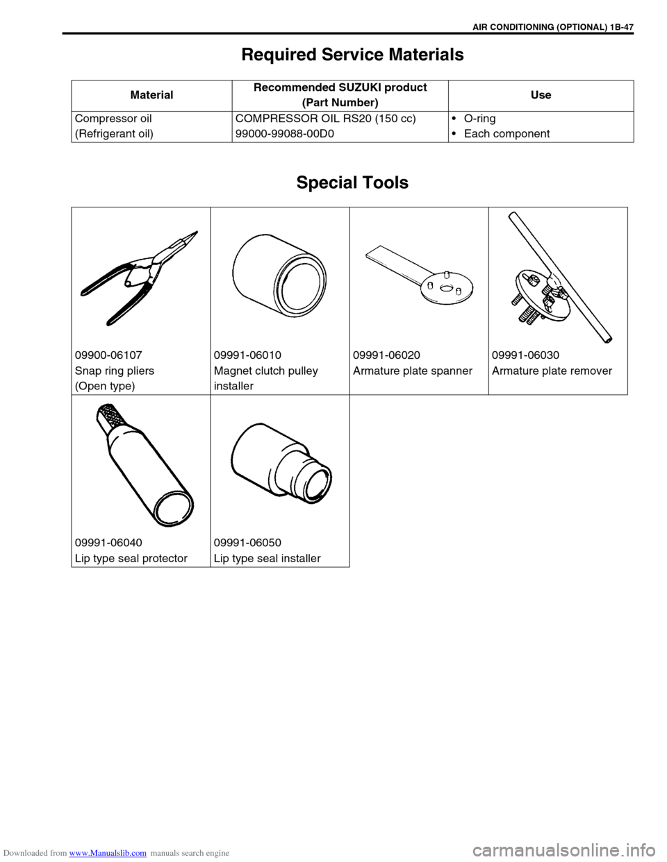
Required Service Materials
Special Tools
MaterialRecommended SUZUKI product
(Part Number)Use
Compressor oil
(Refrigerant oil)COMPRESSOR OIL RS20 (150 cc)
99000-99088-00D0O-ring
Each component
09900-06107 09991-06010 09991-06020 09991-06030
Snap ring pliers
(Open type)Magnet clutch pulley
installerArmature plate spanner Armature plate remover
09991-06040 09991-06050
Lip type seal protector Lip type seal installer
Page 131 of 687
Downloaded from www.Manualslib.com manuals search engine 3B-10 STEERING GEAR BOX (MANUAL TYPE) AND LINKAGE
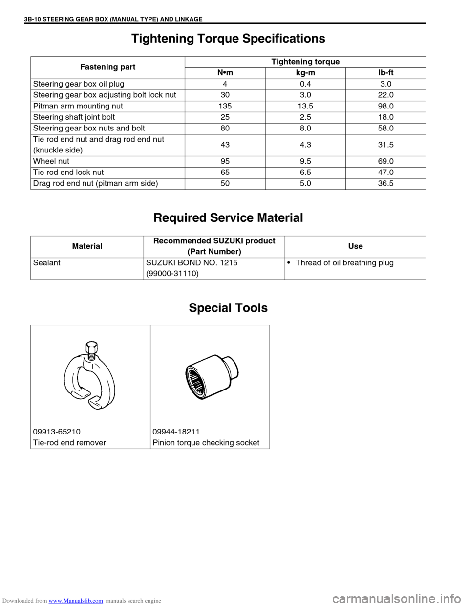
Tightening Torque Specifications
Required Service Material
Special Tools
Fastening partTightening torque
Nm kg-m lb-ft
Steering gear box oil plug 4 0.4 3.0
Steering gear box adjusting bolt lock nut 30 3.0 22.0
Pitman arm mounting nut 135 13.5 98.0
Steering shaft joint bolt 25 2.5 18.0
Steering gear box nuts and bolt 80 8.0 58.0
Tie rod end nut and drag rod end nut
(knuckle side)43 4.3 31.5
Wheel nut 95 9.5 69.0
Tie rod end lock nut 65 6.5 47.0
Drag rod end nut (pitman arm side) 50 5.0 36.5
MaterialRecommended SUZUKI product
(Part Number)Use
Sealant SUZUKI BOND NO. 1215
(99000-31110)Thread of oil breathing plug
09913-65210 09944-18211
Tie-rod end remover Pinion torque checking socket
Page 152 of 687
Downloaded from www.Manualslib.com manuals search engine POWER STEERING (P/S) SYSTEM (If equipped) 3B1-21
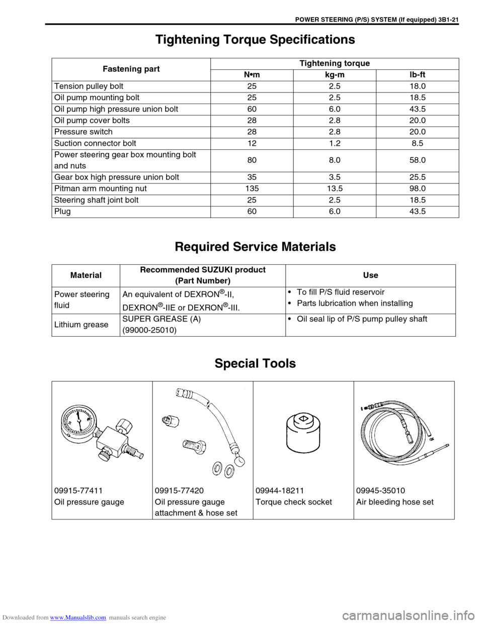
Tightening Torque Specifications
Required Service Materials
Special Tools
Fastening partTightening torque
Nm kg-m lb-ft
Tension pulley bolt 25 2.5 18.0
Oil pump mounting bolt 25 2.5 18.5
Oil pump high pressure union bolt 60 6.0 43.5
Oil pump cover bolts 28 2.8 20.0
Pressure switch 28 2.8 20.0
Suction connector bolt 12 1.2 8.5
Power steering gear box mounting bolt
and nuts80 8.0 58.0
Gear box high pressure union bolt 35 3.5 25.5
Pitman arm mounting nut 135 13.5 98.0
Steering shaft joint bolt 25 2.5 18.5
Plug 60 6.0 43.5
MaterialRecommended SUZUKI product
(Part Number)Use
Power steering
fluidAn equivalent of DEXRON
®-II,
DEXRON
®-IIE or DEXRON®-III.To fill P/S fluid reservoir
Parts lubrication when installing
Lithium greaseSUPER GREASE (A)
(99000-25010)Oil seal lip of P/S pump pulley shaft
09915-77411 09915-77420 09944-18211 09945-35010
Oil pressure gauge Oil pressure gauge
attachment & hose setTorque check socket Air bleeding hose set
Page 155 of 687
Downloaded from www.Manualslib.com manuals search engine 3C-2 STEERING WHEEL AND COLUMN
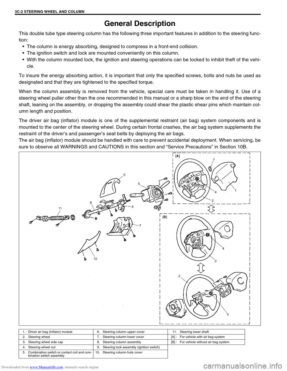
General Description
This double tube type steering column has the following three important features in addition to the steering func-
tion:
The column is energy absorbing, designed to compress in a front-end collision.
The ignition switch and lock are mounted conveniently on this column.
With the column mounted lock, the ignition and steering operations can be locked to inhibit theft of the vehi-
cle.
To insure the energy absorbing action, it is important that only the specified screws, bolts and nuts be used as
designated and that they are tightened to the specified torque.
When the column assembly is removed from the vehicle, special care must be taken in handling it. Use of a
steering wheel puller other than the one recommended in this manual or a sharp blow on the end of the steering
shaft, leaning on the assembly, or dropping the assembly could shear the plastic shear pins which maintain col-
umn length and position.
The driver air bag (inflator) module is one of the supplemental restraint (air bag) system components and is
mounted to the center of the steering wheel. During certain frontal crashes, the air bag system supplements the
restraint of the driver’s and passenger’s seat belts by deploying the air bags.
The air bag (inflator) module should be handled with care to prevent accidental deployment. When servicing, be
sure to observe all WARNINGS and CAUTIONS in this section and “Service Precautions” in Section 10B.
1. Driver air bag (inflator) module 6. Steering column upper cover 11. Steering lower shaft
2. Steering wheel 7. Steering column lower cover [A] : For vehicle with air bag system
3. Steering wheel side cap 8. Steering column assembly [B] : For vehicle without air bag system
4. Steering wheel nut 9. Steering lock assembly (ignition switch)
5. Combination switch or contact coil and com-
bination switch assembly10. Steering column hole cover
Page 217 of 687

Downloaded from www.Manualslib.com manuals search engine 3D-44 FRONT SUSPENSION
Tightening Torque Specifications
Required Service Material
Fastening partTightening torque
Nm kg-m lb-ft
Stabilizer mount bracket bolt 20 2.0 14.5
Stabilizer ball joint nut 50 5.0 36.5
Shock absorber lock nut 29 2.9 21.0
Shock absorber lower nut 90 9.0 65.0
Brake caliper carrier bolt 85 8.5 61.5
Wheel bearing lock nut 220 22.0 160.0
Wheel bearing lock washer screw 1.5 0.15 1.0
Air locking hub bolt 48 4.8 35.0
Wheel spindle bolt 50 5.0 36.5
Kingpin bolt 25 2.5 18.0
Knuckle seal cover bolt 10 1.0 7.5
Tie-rod end nut
43 4.3 31.5
Drag-rod end nut (Knuckle side)
Lateral rod bolt and nut
90 9.0 65.0
Leading arm nut
Front differential carrier bolt 23 2.3 17.0
Front propeller shaft flange bolt 50 5.0 36.5
Wheel nut 95 9.5 69.0
Vacuum pipe clamp bolt 5.5 0.55 4.0
MaterialRecommended SUZUKI product
(Part Number)Use
Lithium grease SUZUKI SUPER GREASE (A)
(99000-25010)Knuckle seal / axle shaft oil seal
Recess of wheel spindles
Wheel hub oil seal
Wheel bearing
Spindle thrust washer
Spindle bush (inside and flange
part)
Spindle oil seal
SUZUKI SUPER GREASE (C)
(99000-25030)Kingpin bearing
Axle shaft joint (for 4WD)
Sealant SUZUKI BOND NO. 1215
(99000-31110)Mating surfaces of wheel spindle
and knuckle
Mating surface of differential carrier
and axle housing
Sealing compound SUZUKI SEALING COMPOUND
366E
(99000-31090)Mating surface of wheel spindle and
knuckle
Kingpin
Mating surfaces of hub cap and
wheel hub