ransmission gear ratio SUZUKI JIMNY 2005 3.G Service Workshop Manual
[x] Cancel search | Manufacturer: SUZUKI, Model Year: 2005, Model line: JIMNY, Model: SUZUKI JIMNY 2005 3.GPages: 687, PDF Size: 13.38 MB
Page 52 of 687

Downloaded from www.Manualslib.com manuals search engine MAINTENANCE AND LUBRICATION 0B-21
GEARSHIFT OR SELECTOR LEVER (TRANSMISSION)
Check gear shift or selector lever for smooth shifting to all positions and for good performance of transmission in
any position.
With automatic transmission equipped vehicle, also check that shift indicator indicates properly according to
which position selector lever is shifted to.
With automatic transmission equipped vehicle, make sure that vehicle is at complete stop when shifting selector
lever to “P” range position and release all brakes.
BRAKE
Foot Brake
Check the following:
that brake pedal has proper travel,
that brake works properly,
that it is free from noise,
that braking force is applied equally on all wheels,
and that brake do not drag.
Parking Brake
Check that lever has proper travel.
Check to ensure that parking brake is fully effective when the vehicle is stopped on the safe slope and brake
lever is pulled all the way.
STEERING
Check to ensure that steering wheel is free from instability, or abnormally heavy feeling.
Check that the vehicle does not wander or pull to one side.
ENGINE
Check that engine responds readily at all speeds.
Check that engine is free from abnormal noise and abnormal vibration.
BODY, WHEELS AND POWER TRANSMITTING SYSTEM
Check that body, wheels and power transmitting system are free from abnormal noise and abnormal vibration or
any other abnormal condition.
METERS AND GAUGE
Check that speedometer, odometer, fuel meter, temperature gauge, etc. are operating accurately.
LIGHTS
Check that all lights operate properly.
WINDSHIELD DEFROSTER
Periodically check that air comes out from defroster outlet when operating heater or air conditioning.
Set mode control lever to defroster position and fan switch lever to “HI” position for this check. WARNING:
With vehicle parked on a fairly steep slope, make sure nothing is in the way downhill to avoid any per-
sonal injury or property damage. Be prepared to apply regular brake quickly even if vehicle should
start to move.
Page 257 of 687

Downloaded from www.Manualslib.com manuals search engine 4B-4 PROPELLER SHAFTS
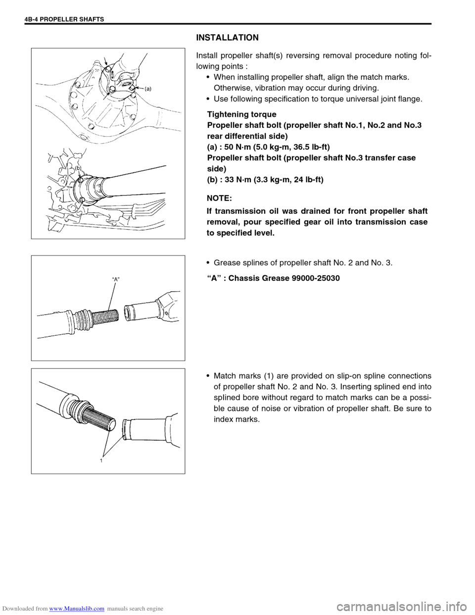
INSTALLATION
Install propeller shaft(s) reversing removal procedure noting fol-
lowing points :
When installing propeller shaft, align the match marks.
Otherwise, vibration may occur during driving.
Use following specification to torque universal joint flange.
Tightening torque
Propeller shaft bolt (propeller shaft No.1, No.2 and No.3
rear differential side)
(a) : 50 N·m (5.0 kg-m, 36.5 lb-ft)
Propeller shaft bolt (propeller shaft No.3 transfer case
side)
(b) : 33 N·m (3.3 kg-m, 24 lb-ft)
Grease splines of propeller shaft No. 2 and No. 3.
“A” : Chassis Grease 99000-25030
Match marks (1) are provided on slip-on spline connections
of propeller shaft No. 2 and No. 3. Inserting splined end into
spIined bore without regard to match marks can be a possi-
ble cause of noise or vibration of propeller shaft. Be sure to
index marks. NOTE:
If transmission oil was drained for front propeller shaft
removal, pour specified gear oil into transmission case
to specified level.
Page 375 of 687

Downloaded from www.Manualslib.com manuals search engine 6-18 ENGINE GENERAL INFORMATION AND DIAGNOSIS
DTC NO. DETECTING ITEM DETECTING CONDITION
(DTC will set when detecting :)MIL
P0702 Transmission Control System Electrical
Refer to Section 7B.
These DTCs can not be read on vehicle without
Immobilizer indicator lamp (by ECM application of
SUZUKI scan tool). P0705 Temperature Sensor Circuit Malfunction
P0710Transmission Temperature Sensor Circuit Mal-
function
P0715Input / Turbine Speed Sensor Circuit Malfunc-
tion
P0720Output Shaft Speed Sensor Circuit Malfunc-
tion
P0725 Engine Speed Input Circuit Malfunction
P0730 Incorrect Gear Ratio
P0743 Torque Converter Clutch Circuit Electrical
P0753 Shift Solenoid A Electrical
P0758 Shift Solenoid B Electrical
P0763 Shift Solenoid C Electrical
P0768 Shift Solenoid D Electrical
P1700 Throttle Position Signal Input Malfunction
P1702Internal Control Module Memory Check Some
Error
P1709Engine Coolant Temperature Signal Input
Malfunction
P1887 Transfer Signal
P1620
(No.84)ECU code not registered
Refer to Section 8G. P1621
(No.83)No ECU code transmitted from Immobilizer
Control Module
P1622
(No.82)Faulty in ECM
P1623
(No.81)ECU code not matched
NOTE:
For ( ) marked No. in DTC column, it is used for vehicle without Immobilizer indicator lamp.
DTC No.12 appears when none of the other codes is identified (vehicle without Immobilizer indica-
tor lamp).