viscosity SUZUKI JIMNY 2005 3.G Service Workshop Manual
[x] Cancel search | Manufacturer: SUZUKI, Model Year: 2005, Model line: JIMNY, Model: SUZUKI JIMNY 2005 3.GPages: 687, PDF Size: 13.38 MB
Page 39 of 687
Downloaded from www.Manualslib.com manuals search engine 0B-8 MAINTENANCE AND LUBRICATION
6) Replenish oil until oil level is brought to FULL level mark on
dipstick. (oil pan and oil filter capacity). The filler inlet is at
the top of the cylinder head cover.
It is recommended to use engine oil of SE, SF, SG, SH, SJ or
SL grade.
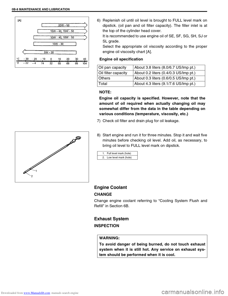
Select the appropriate oil viscosity according to the proper
engine oil viscosity chart [A].
Engine oil specification
7) Check oil filter and drain plug for oil leakage.
8) Start engine and run it for three minutes. Stop it and wait five
minutes before checking oil level. Add oil, as necessary, to
bring oil level to FULL level mark on dipstick.
Engine Coolant
CHANGE
Change engine coolant referring to “Cooling System Flush and
Refill” in Section 6B.
Exhaust System
INSPECTION
Oil pan capacity About 3.8 liters (8.0/6.7 US/lmp pt.)
Oil filter capacity About 0.2 liters (0.4/0.3 US/lmp pt.)
Others About 0.3 liters (0.6/0.5 US/lmp pt.)
Total About 4.3 liters (9.1/7.6 US/lmp pt.)
NOTE:
Engine oil capacity is specified. However, note that the
amount of oil required when actually changing oil may
somewhat differ from the data in the table depending on
various conditions (temperature, viscosity, etc.)
1. Full level mark (hole)
2. Low level mark (hole)
WARNING:
To avoid danger of being burned, do not touch exhaust
system when it is still hot. Any service on exhaust sys-
tem should be performed when it is cool.
Page 134 of 687
Downloaded from www.Manualslib.com manuals search engine POWER STEERING (P/S) SYSTEM (If equipped) 3B1-3
Diagnosis
Diagnosis Table
Condition Possible Cause Correction
Steering wheel feels
heavy
(at low speed)Fluid deteriorated, low viscosity, different type of
fluid mixedChange fluid.
Pipes or hoses deformed, air entering through
jointCorrect or replace.
Insufficient air bleeding from piping Bleed air.
Belt worn, lacking in tension Adjust belt tension or replace belt
as necessary.
Tire inflation pressure too low Inflate tire.
Wheel alignment out of adjustment Adjust front wheel alignment.
Steering wheel installed improperly (twisted) Install steering wheel correctly.
Hydraulic pressure failing to rise (See NOTE
“A”.)Replace P/S pump.
Slow hydraulic pressure rise (See NOTE “A”.)
Steering wheel feels
heavy momentarily
when turning it to the
left or right.Air drawn in due to insufficient amount of fluid Add fluid and bleed air.
Slipping belt Adjust belt tension or replace belt
as necessary.
No idle-up (See NOTE
“B”.)Defective pressure switch Replace pressure switch
(terminal set).
NOTE:
“A” : Be sure to warm up engine fully before performing this check. Pump vanes are sometimes
hard to come out where temperature is low.
“B” : Acceptable if idling speed does not drop.
Condition Possible Cause Correction
Steering wheel returns
slowly from turns.
(See NOTE “C”.)Dust or foreign object mixed in fluid Change fluid.
Deformed pipes or hoses Correct or replace.
Steering column installed improperly Install correctly.
Wheel alignment maladjusted Adjust.
Linkage or joints not operating smoothly Correct.
Vehicle pulls to one
side during straight
driving.Low or uneven tire inflation pressure Inflate tire (s) as necessary.
Wheel alignment maladjusted Adjust.
Defective spool valve Replace gear box assembly.
Steering wheel play is
large and vehicle wan-
ders.Loose steering shaft nut Retighten.
Loose linkage or joint Retighten.
Loose gear box fixing bolt Retighten.
Front wheel bearing worn Replace.
Fluid leakage
Loose joints of hydraulic pressure pipes and
hosesRetighten.
Deformed or damaged pipes or hoses Correct or replace.
Gear box Replace gear box assembly.
Page 284 of 687
Downloaded from www.Manualslib.com manuals search engine BRAKES 5-23
INSPECTION
Cylinder Slide Bush
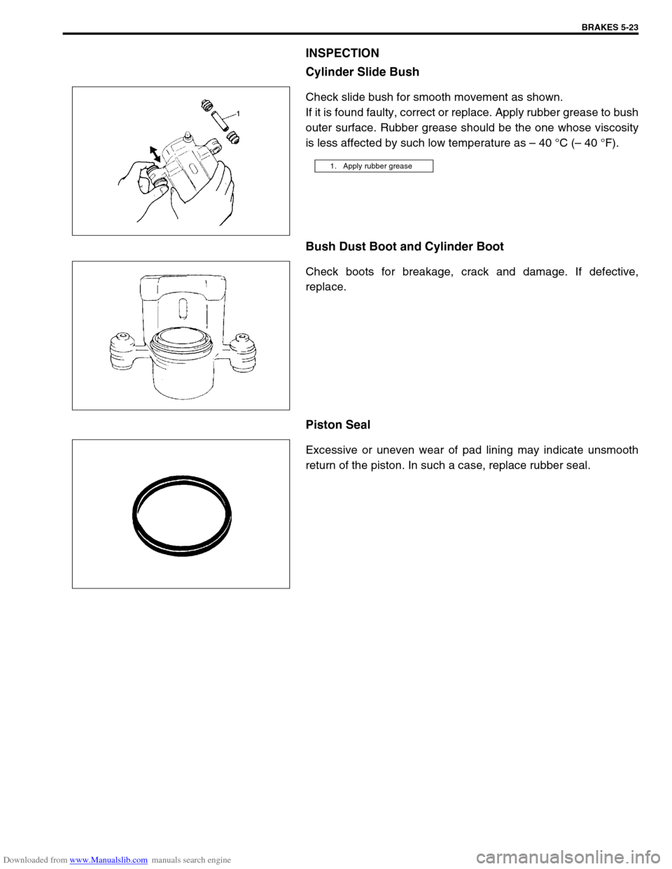
Check slide bush for smooth movement as shown.
If it is found faulty, correct or replace. Apply rubber grease to bush
outer surface. Rubber grease should be the one whose viscosity
is less affected by such low temperature as – 40 °C (– 40 °F).
Bush Dust Boot and Cylinder Boot
Check boots for breakage, crack and damage. If defective,
replace.
Piston Seal
Excessive or uneven wear of pad lining may indicate unsmooth
return of the piston. In such a case, replace rubber seal.
1. Apply rubber grease
Page 285 of 687
Downloaded from www.Manualslib.com manuals search engine 5-24 BRAKES
ASSEMBLY
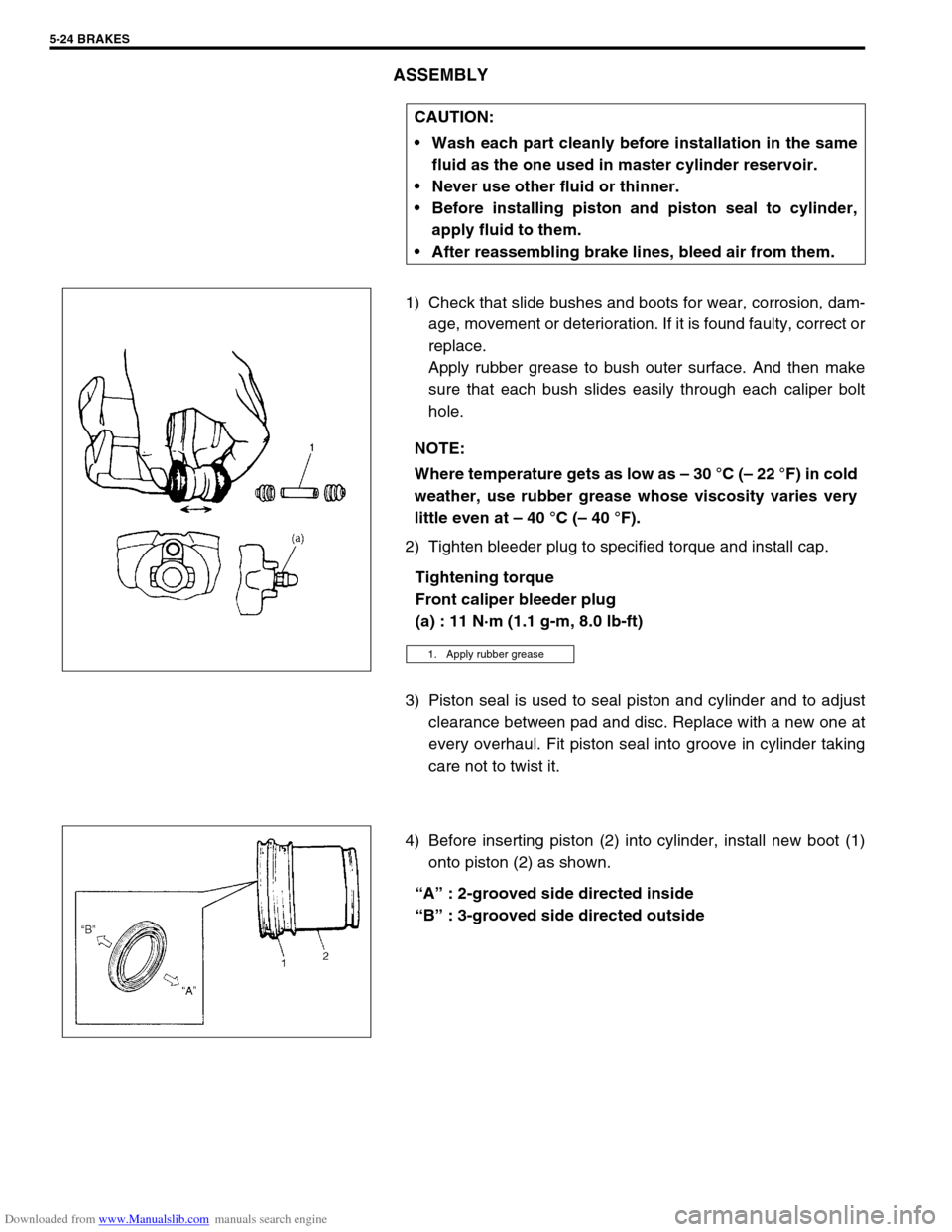
1) Check that slide bushes and boots for wear, corrosion, dam-
age, movement or deterioration. If it is found faulty, correct or
replace.
Apply rubber grease to bush outer surface. And then make
sure that each bush slides easily through each caliper bolt
hole.
2) Tighten bleeder plug to specified torque and install cap.
Tightening torque
Front caliper bleeder plug
(a) : 11 N·m (1.1 g-m, 8.0 lb-ft)
3) Piston seal is used to seal piston and cylinder and to adjust
clearance between pad and disc. Replace with a new one at
every overhaul. Fit piston seal into groove in cylinder taking
care not to twist it.
4) Before inserting piston (2) into cylinder, install new boot (1)
onto piston (2) as shown.
“A” : 2-grooved side directed inside
“B” : 3-grooved side directed outside CAUTION:
Wash each part cleanly before installation in the same
fluid as the one used in master cylinder reservoir.
Never use other fluid or thinner.
Before installing piston and piston seal to cylinder,
apply fluid to them.
After reassembling brake lines, bleed air from them.
NOTE:
Where temperature gets as low as – 30 °C (– 22 °F) in cold
weather, use rubber grease whose viscosity varies very
little even at – 40 °C (– 40 °F).
1. Apply rubber grease
Page 383 of 687
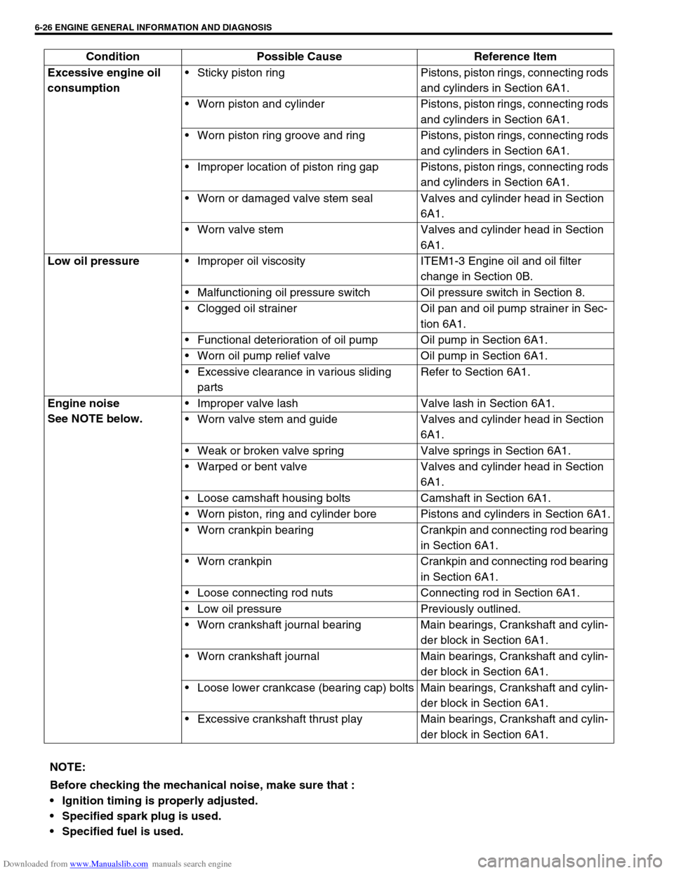
Downloaded from www.Manualslib.com manuals search engine 6-26 ENGINE GENERAL INFORMATION AND DIAGNOSIS
Excessive engine oil
consumptionSticky piston ring Pistons, piston rings, connecting rods
and cylinders in Section 6A1.
Worn piston and cylinder Pistons, piston rings, connecting rods
and cylinders in Section 6A1.
Worn piston ring groove and ring Pistons, piston rings, connecting rods
and cylinders in Section 6A1.
Improper location of piston ring gap Pistons, piston rings, connecting rods
and cylinders in Section 6A1.
Worn or damaged valve stem seal Valves and cylinder head in Section
6A1.
Worn valve stem Valves and cylinder head in Section
6A1.
Low oil pressure
Improper oil viscosity ITEM1-3 Engine oil and oil filter
change in Section 0B.
Malfunctioning oil pressure switch Oil pressure switch in Section 8.
Clogged oil strainer Oil pan and oil pump strainer in Sec-
tion 6A1.
Functional deterioration of oil pump Oil pump in Section 6A1.
Worn oil pump relief valve Oil pump in Section 6A1.
Excessive clearance in various sliding
partsRefer to Section 6A1.
Engine noise
See NOTE below.Improper valve lash Valve lash in Section 6A1.
Worn valve stem and guide Valves and cylinder head in Section
6A1.
Weak or broken valve spring Valve springs in Section 6A1.
Warped or bent valve Valves and cylinder head in Section
6A1.
Loose camshaft housing bolts Camshaft in Section 6A1.
Worn piston, ring and cylinder bore Pistons and cylinders in Section 6A1.
Worn crankpin bearing Crankpin and connecting rod bearing
in Section 6A1.
Worn crankpin Crankpin and connecting rod bearing
in Section 6A1.
Loose connecting rod nuts Connecting rod in Section 6A1.
Low oil pressure Previously outlined.
Worn crankshaft journal bearing Main bearings, Crankshaft and cylin-
der block in Section 6A1.
Worn crankshaft journal Main bearings, Crankshaft and cylin-
der block in Section 6A1.
Loose lower crankcase (bearing cap) bolts Main bearings, Crankshaft and cylin-
der block in Section 6A1.
Excessive crankshaft thrust play Main bearings, Crankshaft and cylin-
der block in Section 6A1. Condition Possible Cause Reference Item
NOTE:
Before checking the mechanical noise, make sure that :
Ignition timing is properly adjusted.
Specified spark plug is used.
Specified fuel is used.