mirror SUZUKI KIZASHI 2010 1.G User Guide
[x] Cancel search | Manufacturer: SUZUKI, Model Year: 2010, Model line: KIZASHI, Model: SUZUKI KIZASHI 2010 1.GPages: 388, PDF Size: 4.94 MB
Page 42 of 388
2-23BEFORE DRIVING
57L20-03E
NOTE:
If your vehicle is equipped with the heated
outside rearview mirrors, refer to “Heated
Rear Window and Heated Outside Rear-
view Mirrors (if equipped) Switch” in this
section.
Front SeatsStandard Seat (if equipped)Adjusting seat position
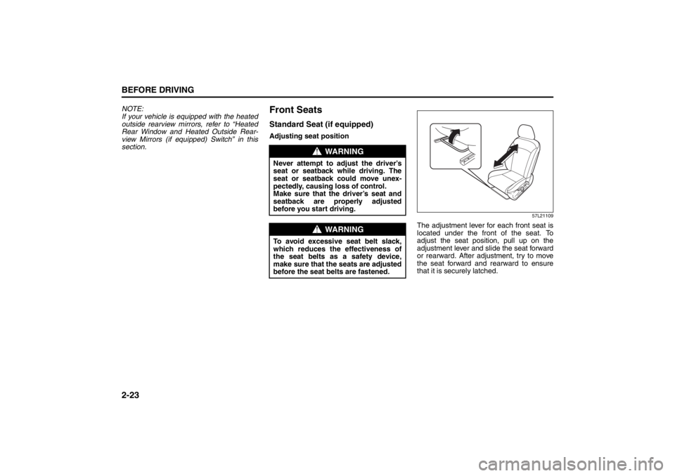
57L21109
The adjustment lever for each front seat is
located under the front of the seat. To
adjust the seat position, pull up on the
adjustment lever and slide the seat forward
or rearward. After adjustment, try to move
the seat forward and rearward to ensure
that it is securely latched.
WARNING
Never attempt to adjust the driver’s
seat or seatback while driving. The
seat or seatback could move unex-
pectedly, causing loss of control.
Make sure that the driver’s seat and
seatback are properly adjusted
before you start driving.
WARNING
To avoid excessive seat belt slack,
which reduces the effectiveness of
the seat belts as a safety device,
make sure that the seats are adjusted
before the seat belts are fastened.
Seat Belts and Child Restraint Systems: 3
Page 130 of 388
2-111BEFORE DRIVING
57L20-03E
Horn
57L21119
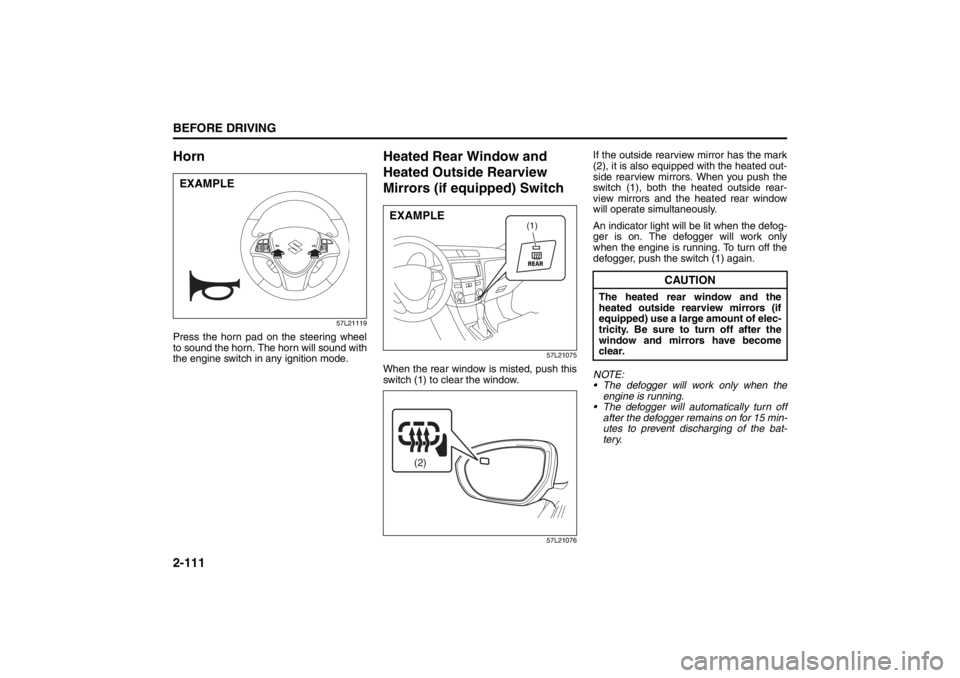
Press the horn pad on the steering wheel
to sound the horn. The horn will sound with
the engine switch in any ignition mode.
Heated Rear Window and
Heated Outside Rearview
Mirrors (if equipped) Switch
57L21075
When the rear window is misted, push this
switch (1) to clear the window.
57L21076
If the outside rearview mirror has the mark
(2), it is also equipped with the heated out-
side rearview mirrors. When you push the
switch (1), both the heated outside rear-
view mirrors and the heated rear window
will operate simultaneously.
An indicator light will be lit when the defog-
ger is on. The defogger will work only
when the engine is running. To turn off the
defogger, push the switch (1) again.
NOTE:
The defogger will work only when the
engine is running.
The defogger will automatically turn off
after the defogger remains on for 15 min-
utes to prevent discharging of the bat-
tery.
EXAMPLE
(1)
EXAMPLE
(2)
CAUTION
The heated rear window and the
heated outside rearview mirrors (if
equipped) use a large amount of elec-
tricity. Be sure to turn off after the
window and mirrors have become
clear.
Page 132 of 388
3-1OPERATING YOUR VEHICLE
57L20-03E
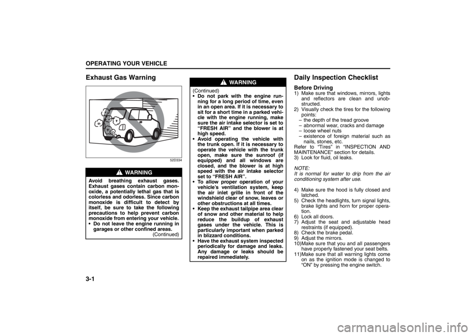
Exhaust Gas Warning
52D334
Daily Inspection ChecklistBefore Driving1) Make sure that windows, mirrors, lights
and reflectors are clean and unob-
structed.
2) Visually check the tires for the following
points:
– the depth of the tread groove
– abnormal wear, cracks and damage
– loose wheel nuts
– existence of foreign material such as
nails, stones, etc.
Refer to “Tires” in “INSPECTION AND
MAINTENANCE” section for details.
3) Look for fluid, oil leaks.
NOTE:
It is normal for water to drip from the air
conditioning system after use.
4) Make sure the hood is fully closed and
latched.
5) Check the headlights, turn signal lights,
brake lights and horn for proper opera-
tion.
6) Lock all doors.
7) Adjust the seat and adjustable head
restraints (if equipped).
8) Check the brake pedal.
9) Adjust the mirrors.
10)Make sure that you and all passengers
have properly fastened your seat belts.
11)Make sure that all warning lights come
on as the ignition mode is changed to
“ON” by pressing the engine switch.
WARNING
Avoid breathing exhaust gases.
Exhaust gases contain carbon mon-
oxide, a potentially lethal gas that is
colorless and odorless. Since carbon
monoxide is difficult to detect by
itself, be sure to take the following
precautions to help prevent carbon
monoxide from entering your vehicle.
Do not leave the engine running in
garages or other confined areas.
(Continued)
WARNING
(Continued)
Do not park with the engine run-
ning for a long period of time, even
in an open area. If it is necessary to
sit for a short time in a parked vehi-
cle with the engine running, make
sure the air intake selector is set to
“FRESH AIR” and the blower is at
high speed.
Avoid operating the vehicle with
the trunk open. If it is necessary to
operate the vehicle with the trunk
open, make sure the sunroof (if
equipped) and all windows are
closed, and the blower is at high
speed with the air intake selector
set to “FRESH AIR”.
To allow proper operation of your
vehicle’s ventilation system, keep
the air inlet grille in front of the
windshield clear of snow, leaves or
other obstructions at all times.
Keep the exhaust tailpipe area clear
of snow and other material to help
reduce the buildup of exhaust
gases under the vehicle. This is
particularly important when parked
in blizzard conditions.
Have the exhaust system inspected
periodically for damage and leaks.
Any damage or leaks should be
repaired immediately.
Ignition Switch: 8
Page 155 of 388
3-24
OPERATING YOUR VEHICLE
57L20-03E
taken by the ultrasonic wave to reach the
obstacle and return from it, from which it
determines the obstacle’s position.
The parking sensor function can be used
when you press the engine switch to
change the ignition mode to “ON”, the
gearshift lever is in the “R” position and
the parking sensor switch is in the ON
position. This function is helpful when
parallel-parking the vehicle, steering the
vehicle into the garage or moving slowly
in a place with obstacles.
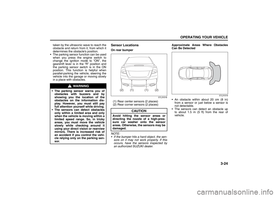
Sensor LocationsOn rear bumper
57L31018
(1) Rear center sensors (2 places)
(2) Rear corner sensors (2 places)
NOTE:
If the bumper hits a hard object, the sen-
sors on it may not work properly. If this
occurs, have the sensors inspected by
an authorized SUZUKI dealer.Approximate Areas Where Obstacles
Can Be Detected
57L31019
An obstacle within about 20 cm (8 in)
from a sensor or just below a sensor is
not detectable.
The sensors can detect an obstacle up
to about 1.5 m (5 ft) from the rear of
vehicle.
WARNING
The parking sensor warns you of
obstacles with buzzers and by
showing you the location of the
obstacles on the information dis-
play. However, you must still pay
full attention yourself while driving.
The sensors can detect obstacles
only within a limited area and only
when the vehicle is moving within a
limited speed range. So, in tricky
areas, you must move the vehicle
slowly while checking around it
using your direct vision or rearview
mirrors. There is increased risk of
an accident if you control the vehi-
cle relying only on the parking sen-
sor.
CAUTION
Avoid hitting the sensor areas or
directing the nozzle of a high-pres-
sure car washer onto the sensor
areas. Otherwise, the sensors may be
damaged.
(1)
(1)
(2)
(2)
Page 256 of 388
5-77OTHER CONTROLS AND EQUIPMENT
57L20-03E
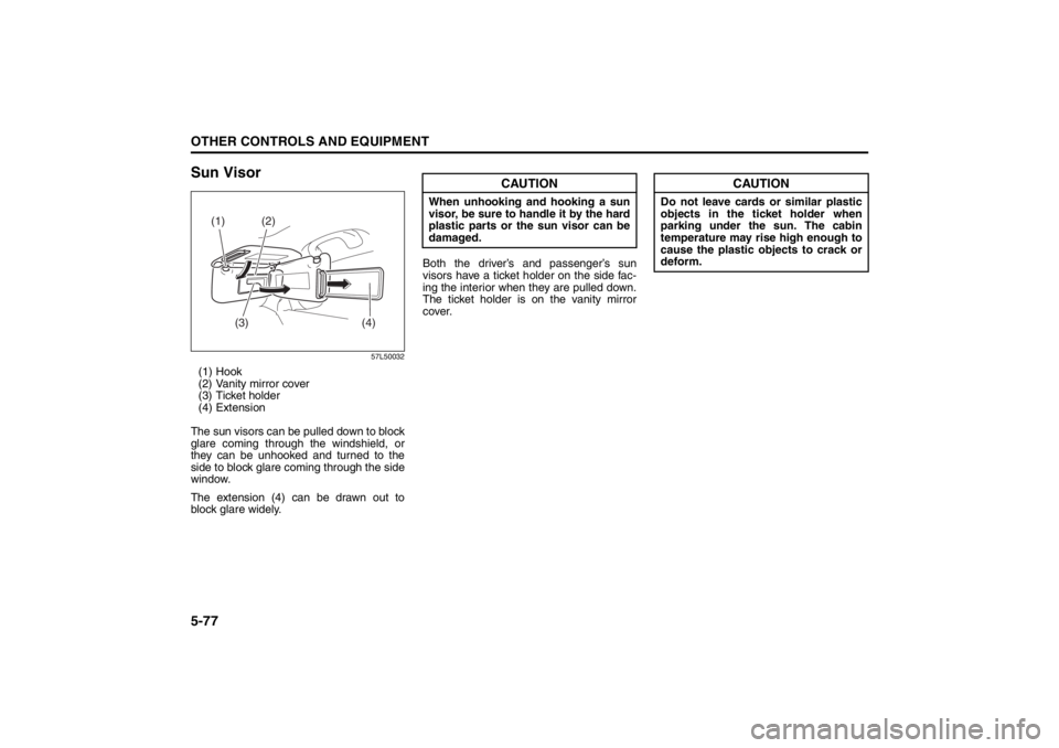
Sun Visor
57L50032
(1) Hook
(2) Vanity mirror cover
(3) Ticket holder
(4) Extension
The sun visors can be pulled down to block
glare coming through the windshield, or
they can be unhooked and turned to the
side to block glare coming through the side
window.
The extension (4) can be drawn out to
block glare widely. Both the driver’s and passenger’s sun
visors have a ticket holder on the side fac-
ing the interior when they are pulled down.
The ticket holder is on the vanity mirror
cover.
(1)
(2)
(3)
(4)
CAUTION
When unhooking and hooking a sun
visor, be sure to handle it by the hard
plastic parts or the sun visor can be
damaged.
CAUTION
Do not leave cards or similar plastic
objects in the ticket holder when
parking under the sun. The cabin
temperature may rise high enough to
cause the plastic objects to crack or
deform.
Page 325 of 388
7-40
INSPECTION AND MAINTENANCE
57L20-03E
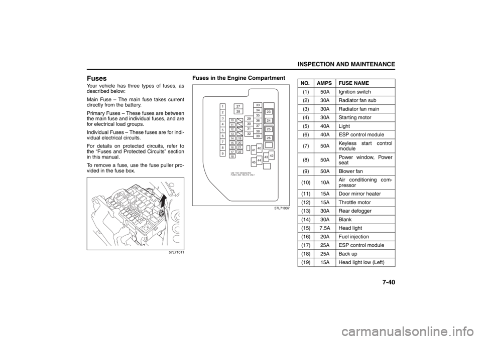
FusesYour vehicle has three types of fuses, as
described below:
Main Fuse – The main fuse takes current
directly from the battery.
Primary Fuses – These fuses are between
the main fuse and individual fuses, and are
for electrical load groups.
Individual Fuses – These fuses are for indi-
vidual electrical circuits.
For details on protected circuits, refer to
the “Fuses and Protected Circuits” section
in this manual.
To remove a fuse, use the fuse puller pro-
vided in the fuse box.
57L71011
Fuses in the Engine Compartment
57L71037
1
10
11
12
13
14
15
16
1719
20
21
22
23
24
25
26 29
30
31
3233
34 27
28
37
38
39
40
41
444342
4535
36
18
2
3
4
5
6
7
8
9
USE THE DESIGNATED
FUSES AND RELAYS ONLY
NO. AMPS FUSE NAME
(1) 50A Ignition switch
(2) 30A Radiator fan sub
(3) 30A Radiator fan main
(4) 30A Starting motor
(5) 40A Light
(6) 40A ESP control module
(7) 50AKeyless start control
module
(8) 50APowe r w i n d ow, Powe r
seat
(9) 50A Blower fan
(10) 10AAir conditioning com-
pressor
(11) 15A Door mirror heater
(12) 15A Throttle motor
(13) 30A Rear defogger
(14) 30A Blank
(15) 7.5A Head light
(16) 20A Fuel injection
(17) 25A ESP control module
(18) 25A Back up
(19) 15A Head light low (Left)
Page 326 of 388
7-41INSPECTION AND MAINTENANCE
57L20-03E
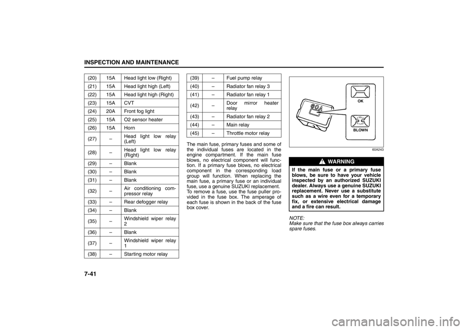
The main fuse, primary fuses and some of
the individual fuses are located in the
engine compartment. If the main fuse
blows, no electrical component will func-
tion. If a primary fuse blows, no electrical
component in the corresponding load
group will function. When replacing the
main fuse, a primary fuse or an individual
fuse, use a genuine SUZUKI replacement.
To remove a fuse, use the fuse puller pro-
vided in the fuse box. The amperage of
each fuse is shown in the back of the fuse
box cover.
60A243
NOTE:
Make sure that the fuse box always carries
spare fuses. (20) 15A Head light low (Right)
(21) 15A Head light high (Left)
(22) 15A Head light high (Right)
(23) 15A CVT
(24) 20A Front fog light
(25) 15A O2 sensor heater
(26) 15A Horn
(27) –Head light low relay
(Left)
(28) –Head light low relay
(Right)
(29) – Blank
(30) – Blank
(31) – Blank
(32) –Air conditioning com-
pressor relay
(33) – Rear defogger relay
(34) – Blank
(35) –Windshield wiper relay
2
(36) – Blank
(37) –Windshield wiper relay
1
(38) – Starting motor relay
(39) – Fuel pump relay
(40) – Radiator fan relay 3
(41) – Radiator fan relay 1
(42) –Door mirror heater
relay
(43) – Radiator fan relay 2
(44) – Main relay
(45) – Throttle motor relay
WARNING
If the main fuse or a primary fuse
blows, be sure to have your vehicle
inspected by an authorized SUZUKI
dealer. Always use a genuine SUZUKI
replacement. Never use a substitute
such as a wire even for a temporary
fix, or extensive electrical damage
and a fire can result.
BLOWNOK
Page 331 of 388
7-46
INSPECTION AND MAINTENANCE
57L20-03E
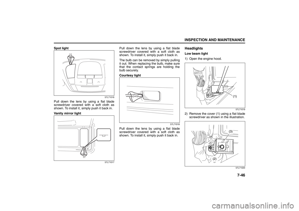
Spot light
57L71016
Pull down the lens by using a flat blade
screwdriver covered with a soft cloth as
shown. To install it, simply push it back in.
Vanity mirror light
57L71017
Pull down the lens by using a flat blade
screwdriver covered with a soft cloth as
shown. To install it, simply push it back in.
The bulb can be removed by simply pulling
it out. When replacing the bulb, make sure
that the contact springs are holding the
bulb securely.
Courtesy light
57L71018
Pull down the lens by using a flat blade
screwdriver covered with a soft cloth as
shown. To install it, simply push it back in.
HeadlightsLow beam light
1) Open the engine hood.
57L71019
2) Remove the cover (1) using a flat blade
screwdriver as shown in the illustration.
57L71020(1)
(3)
(2)
Page 368 of 388

11-2FUSES AND PROTECTED CIRCUITS
57L20-03E57L71037
COLOR/SIZE (AMPS)
FUSE NAME
PROTECTED CIRCUIT
In engine
compartment MAIN
FUSE
BOX(9) RED (50) BLW Blower fan
(10) RED (10) A/C Air conditioning compressor
(11) BLUE (15) MRR HTR Door mirror heater
(12) BLUE (15) THR MOT Throttle motor
(13) GREEN (30) RR DEF Rear defogger
(14) GREEN (30) H/L CLNR Blank
(15) BROWN (7.5) H/L Head light
(16) YELLOW (20) FI Fuel injection
(17) WHITE (25) ABS SOL ESP control module
1
10
11
12
13
14
15
16
1719
20
21
22
23
24
25
26 29
30
31
3233
34 27
28
37
38
39
40
41
444342
4535
36
18
2
3
4
5
6
7
8
9
USE THE DESIGNATED
FUSES AND RELAYS ONLY
Fuses and Protected Circuits: 7
Page 371 of 388

11-5
FUSES AND PROTECTED CIRCUITS
57L20-03E57L71037
COLOR/SIZE (AMPS)
FUSE NAME
PROTECTED CIRCUIT
In engine
compartment MAIN
FUSE
BOX(36) – – Blank
(37) – – Windshield wiper relay 1
(38) – – Starting motor relay
(39) – – Fuel pump relay
(40) – – Radiator fan relay 3
(41) – – Radiator fan relay 1
(42) – – Door mirror heater relay
(43) – – Radiator fan relay 2
(44) – – Main relay
(45) – – Throttle motor relay
1
10
11
12
13
14
15
16
1719
20
21
22
23
24
25
26 29
30
31
3233
34 27
28
37
38
39
40
41
444342
4535
36
18
2
3
4
5
6
7
8
9
USE THE DESIGNATED
FUSES AND RELAYS ONLY