SUZUKI KIZASHI 2010 1.G Owners Manual
Manufacturer: SUZUKI, Model Year: 2010, Model line: KIZASHI, Model: SUZUKI KIZASHI 2010 1.GPages: 388, PDF Size: 4.94 MB
Page 331 of 388
7-46
INSPECTION AND MAINTENANCE
57L20-03E
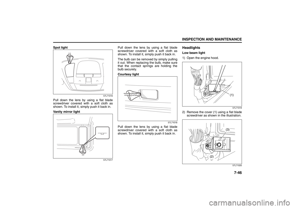
Spot light
57L71016
Pull down the lens by using a flat blade
screwdriver covered with a soft cloth as
shown. To install it, simply push it back in.
Vanity mirror light
57L71017
Pull down the lens by using a flat blade
screwdriver covered with a soft cloth as
shown. To install it, simply push it back in.
The bulb can be removed by simply pulling
it out. When replacing the bulb, make sure
that the contact springs are holding the
bulb securely.
Courtesy light
57L71018
Pull down the lens by using a flat blade
screwdriver covered with a soft cloth as
shown. To install it, simply push it back in.
HeadlightsLow beam light
1) Open the engine hood.
57L71019
2) Remove the cover (1) using a flat blade
screwdriver as shown in the illustration.
57L71020(1)
(3)
(2)
Page 332 of 388
7-47INSPECTION AND MAINTENANCE
57L20-03E
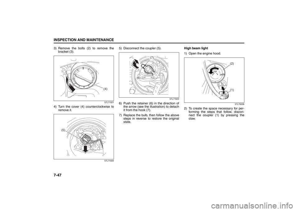
3) Remove the bolts (2) to remove the
bracket (3).
57L71021
4) Turn the cover (4) counterclockwise to
remove it.
57L71022
5) Disconnect the coupler (5).
57L71023
6) Push the retainer (6) in the direction of
the arrow (see the illustration) to detach
it from the hook (7).
7) Replace the bulb, then follow the above
steps in reverse to restore the original
state.High beam light
1) Open the engine hood.
57L70036
2) To create the space necessary for per-
forming the steps that follow, discon-
nect the coupler (1) by pressing the
claw.
(4)
(5)
(7)
(6)
(2)(1)
Page 333 of 388
7-48
INSPECTION AND MAINTENANCE
57L20-03E
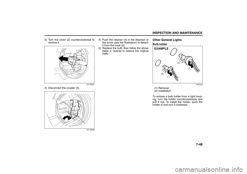
3) Turn the cover (2) counterclockwise to
remove it.
57L70037
4) Disconnect the coupler (3).
57L70038
5) Push the retainer (4) in the direction of
the arrow (see the illustration) to detach
it from the hook (5).
6) Replace the bulb, then follow the above
steps in reverse to restore the original
state.
Other General LightsBulb holder
54G123
(1) Removal
(2) Installation
To remove a bulb holder from a light hous-
ing, turn the holder counterclockwise and
pull it out. To install the holder, push the
holder in and turn it clockwise.
(3)
(4)
(5)
(1)
(1) (2)(2)
EXAMPLE
Page 334 of 388
7-49INSPECTION AND MAINTENANCE
57L20-03E
Bulb
54G124
(3) Removal
(4) Installation
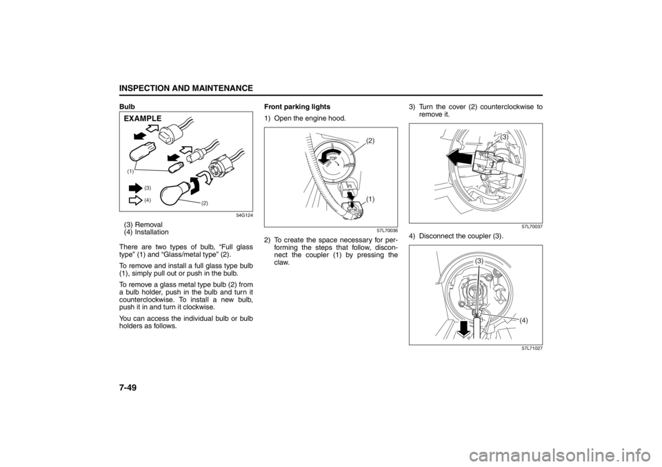
There are two types of bulb, “Full glass
type” (1) and “Glass/metal type” (2).
To remove and install a full glass type bulb
(1), simply pull out or push in the bulb.
To remove a glass metal type bulb (2) from
a bulb holder, push in the bulb and turn it
counterclockwise. To install a new bulb,
push it in and turn it clockwise.
You can access the individual bulb or bulb
holders as follows.Front parking lights
1) Open the engine hood.
57L70036
2) To create the space necessary for per-
forming the steps that follow, discon-
nect the coupler (1) by pressing the
claw.3) Turn the cover (2) counterclockwise to
remove it.
57L70037
4) Disconnect the coupler (3).
57L71027
(1)
(2) (3)
(4)EXAMPLE
(2)(1)
(3)
(4)
(3)
Page 335 of 388
7-50
INSPECTION AND MAINTENANCE
57L20-03E
5) Pull on the cable (4) toward the rear of
the vehicle to remove the bulb socket
(5) from the parking light body.
NOTE:
You can remove the parking light’s bulb
socket only by pulling on the cable, but this
method must never be used to remove the
bulb sockets of any other lights.
6) Replace the bulb, then follow the above
steps in reverse to restore the original
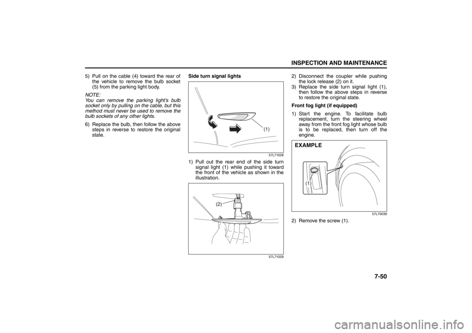
state.Side turn signal lights
57L71028
1) Pull out the rear end of the side turn
signal light (1) while pushing it toward
the front of the vehicle as shown in the
illustration.
57L71029
2) Disconnect the coupler while pushing
the lock release (2) on it.
3) Replace the side turn signal light (1),
then follow the above steps in reverse
to restore the original state.
Front fog light (if equipped)
1) Start the engine. To facilitate bulb
replacement, turn the steering wheel
away from the front fog light whose bulb
is to be replaced, then turn off the
engine.
57L70039
2) Remove the screw (1).
(1)
(2)
(1)
EXAMPLE
Page 336 of 388
7-51INSPECTION AND MAINTENANCE
57L20-03E
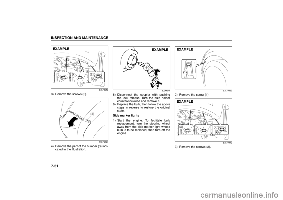
57L70040
3) Remove the screws (2).
57L70041
4) Remove the part of the bumper (3) indi-
cated in the illustration.
80JM071
5) Disconnect the coupler with pushing
the lock release. Turn the bulb holder
counterclockwise and remove it.
6) Replace the bulb, then follow the above
steps in reverse to restore the original
state.
Side marker lights
1) Start the engine. To facilitate bulb
replacement, turn the steering wheel
away from the side marker light whose
bulb is to be replaced, then turn off the
engine.
57L70039
2) Remove the screw (1).
57L70040
3) Remove the screws (2).
(2)
(2)
(2)EXAMPLE
(3)
EXAMPLE
(1)
EXAMPLE
(2)
(2)
(2)EXAMPLE
Page 337 of 388
7-52
INSPECTION AND MAINTENANCE
57L20-03E
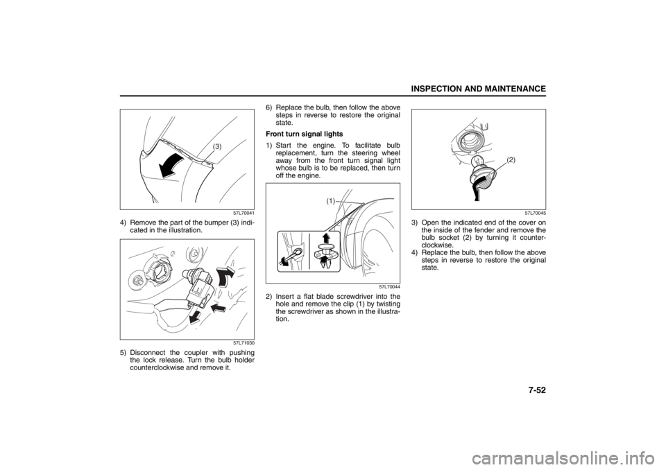
57L70041
4) Remove the part of the bumper (3) indi-
cated in the illustration.
57L71030
5) Disconnect the coupler with pushing
the lock release. Turn the bulb holder
counterclockwise and remove it.6) Replace the bulb, then follow the above
steps in reverse to restore the original
state.
Front turn signal lights
1) Start the engine. To facilitate bulb
replacement, turn the steering wheel
away from the front turn signal light
whose bulb is to be replaced, then turn
off the engine.
57L70044
2) Insert a flat blade screwdriver into the
hole and remove the clip (1) by twisting
the screwdriver as shown in the illustra-
tion.
57L70045
3) Open the indicated end of the cover on
the inside of the fender and remove the
bulb socket (2) by turning it counter-
clockwise.
4) Replace the bulb, then follow the above
steps in reverse to restore the original
state.
(3)
(1)
(2)
Page 338 of 388
7-53INSPECTION AND MAINTENANCE
57L20-03E
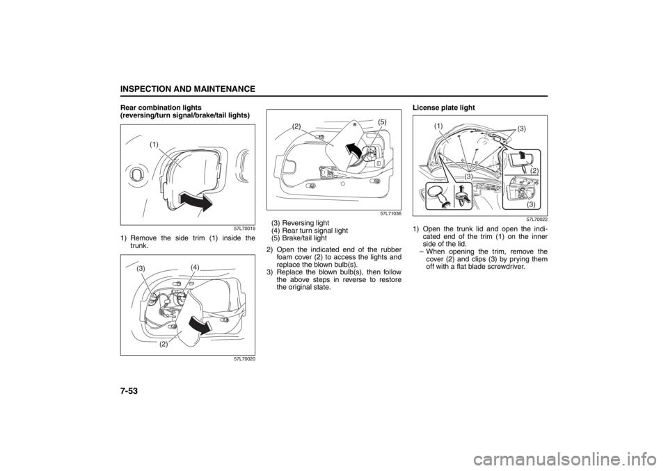
Rear combination lights
(reversing/turn signal/brake/tail lights)
57L70019
1) Remove the side trim (1) inside the
trunk.
57L7002057L71036
(3) Reversing light
(4) Rear turn signal light
(5) Brake/tail light
2) Open the indicated end of the rubber
foam cover (2) to access the lights and
replace the blown bulb(s).
3) Replace the blown bulb(s), then follow
the above steps in reverse to restore
the original state.License plate light
57L70022
1) Open the trunk lid and open the indi-
cated end of the trim (1) on the inner
side of the lid.
– When opening the trim, remove the
cover (2) and clips (3) by prying them
off with a flat blade screwdriver.
(1)
(4)
(3)
(2)
(5)
(2)
(1)
(3)
(3)(2)
(3)
Page 339 of 388
7-54
INSPECTION AND MAINTENANCE
57L20-03E
57L70035
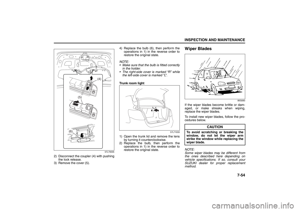
2) Disconnect the coupler (4) with pushing
the lock release.
3) Remove the cover (5).4) Replace the bulb (6), then perform the
operations in 1) in the reverse order to
restore the original state.
NOTE:
Make sure that the bulb is fitted correctly
in the holder.
The right-side cover is marked “R” while
the left-side cover is marked “L”.
Trunk room light
57L71033
1) Open the trunk lid and remove the lens
by turning it counterclockwise.
2) Replace the bulb, then perform the
operations in 1) in the reverse order to
restore the original state.
Wiper Blades
80G083
If the wiper blades become brittle or dam-
aged, or make streaks when wiping,
replace the wiper blades.
To install new wiper blades, follow the pro-
cedures below.
NOTE:
Some wiper blades may be different from
the ones described here depending on
vehicle specifications. If so, consult your
SUZUKI dealer for proper replacement
method.
(6)
(5)
(4)
CAUTION
To avoid scratching or breaking the
window, do not let the wiper arm
strike the window while replacing the
wiper blade.
Page 340 of 388
7-55INSPECTION AND MAINTENANCE
57L20-03E
For windshield wipers
70G119
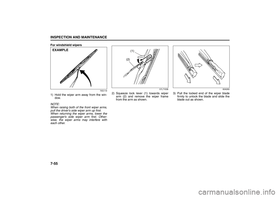
1) Hold the wiper arm away from the win-
dow.
NOTE:
When raising both of the front wiper arms,
pull the driver’s side wiper arm up first.
When returning the wiper arms, lower the
passenger’s side wiper arm first. Other-
wise, the wiper arms may interfere with
each other.
57L71038
2) Squeeze lock lever (1) towards wiper
arm (2) and remove the wiper frame
from the arm as shown.
60A260
3) Pull the locked end of the wiper blade
firmly to unlock the blade and slide the
blade out as shown.
EXAMPLE
(1)
(2)