clock SUZUKI MARUTI 2005 1.G User Guide
[x] Cancel search | Manufacturer: SUZUKI, Model Year: 2005, Model line: MARUTI, Model: SUZUKI MARUTI 2005 1.GPages: 136, PDF Size: 2.93 MB
Page 105 of 136

Downloaded from www.Manualslib.com manuals search engine 10583K
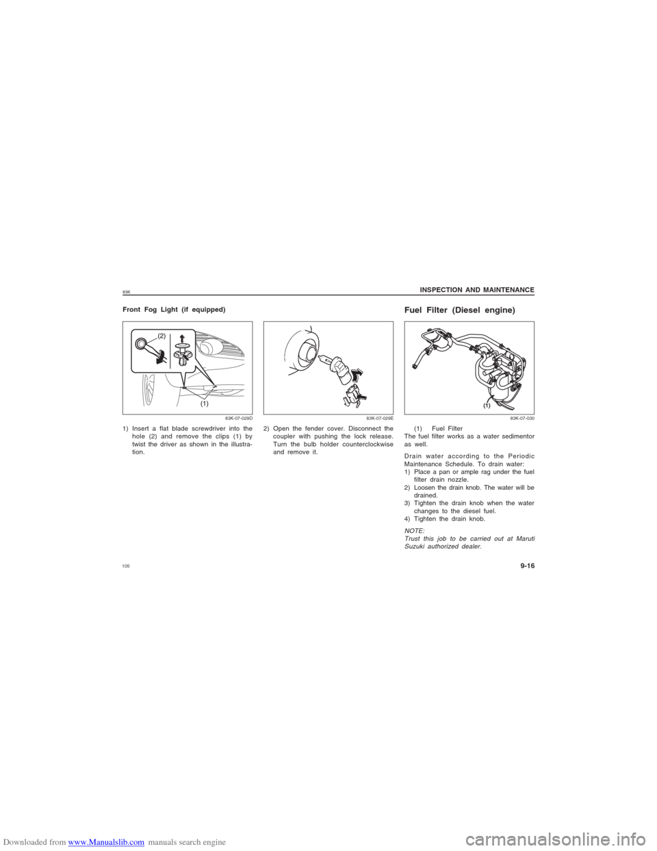
Fuel Filter (Diesel engine)
(1) Fuel Filter
The fuel filter works as a water sedimentor
as well.
Drain water according to the Periodic
Maintenance Schedule. To drain water:
1) Place a pan or ample rag under the fuel
filter drain nozzle.
2) Loosen the drain knob. The water will be
drained.
3) Tighten the drain knob when the water
changes to the diesel fuel.
4) Tighten the drain knob.
NOTE:
Trust this job to be carried out at Maruti
Suzuki authorized dealer.
83K-07-030
Front Fog Light (if equipped)1) Insert a flat blade screwdriver into the
hole (2) and remove the clips (1) by
twist the driver as shown in the illustra-
tion.
83K-07-029D
83K-07-029E
2) Open the fender cover. Disconnect the
coupler with pushing the lock release.
Turn the bulb holder counterclockwise
and remove it.
INSPECTION AND MAINTENANCE
9-16
Page 116 of 136

Downloaded from www.Manualslib.com manuals search engine 11683K
INSPECTION AND MAINTENANCE
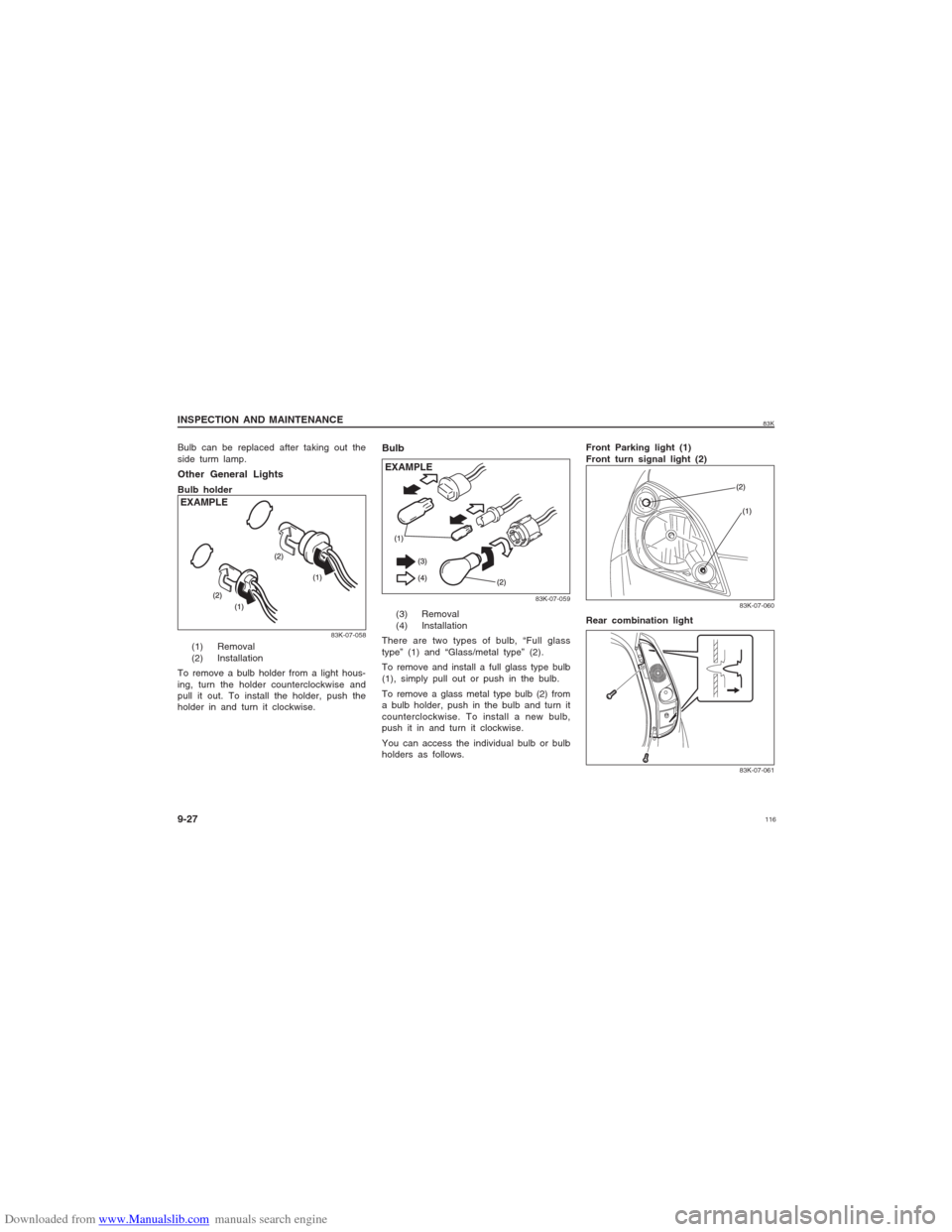
9-27 Other General LightsBulb holder
(1) Removal
(2) Installation
To remove a bulb holder from a light hous-
ing, turn the holder counterclockwise and
pull it out. To install the holder, push the
holder in and turn it clockwise.
Bulb
(3) Removal
(4) Installation
There are two types of bulb, “Full glass
type” (1) and “Glass/metal type” (2).
To remove and install a full glass type bulb
(1), simply pull out or push in the bulb.
To remove a glass metal type bulb (2) from
a bulb holder, push in the bulb and turn it
counterclockwise. To install a new bulb,
push it in and turn it clockwise.
You can access the individual bulb or bulb
holders as follows.Front Parking light (1)
Front turn signal light (2)
Rear combination light
83K-07-058
83K-07-059
83K-07-06083K-07-061
EXAMPLEEXAMPLEBulb can be replaced after taking out the
side turm lamp.
Page 122 of 136

Downloaded from www.Manualslib.com manuals search engine 12283K
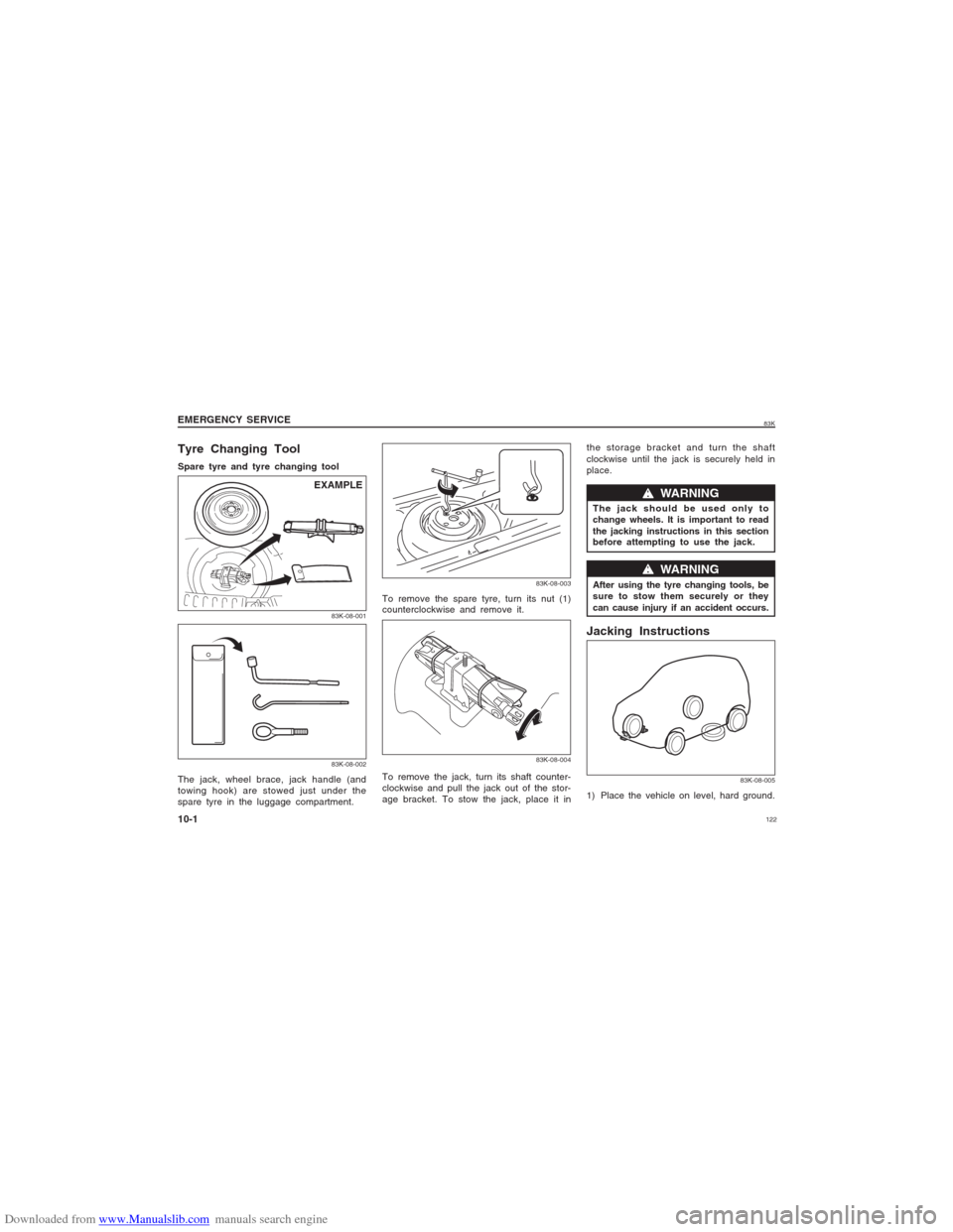
Tyre Changing ToolSpare tyre and tyre changing tool
The jack, wheel brace, jack handle (and
towing hook) are stowed just under the
spare tyre in the luggage compartment.To remove the spare tyre, turn its nut (1)
counterclockwise and remove it.the storage bracket and turn the shaft
clockwise until the jack is securely held in
place.
83K-08-00183K-08-002
83K-08-00383K-08-004
w ww w
w WARNING
The jack should be used only to
change wheels. It is important to read
the jacking instructions in this section
before attempting to use the jack.
w ww w
w WARNING
After using the tyre changing tools, be
sure to stow them securely or they
can cause injury if an accident occurs.
EMERGENCY SERVICE
10-1
To remove the jack, turn its shaft counter-
clockwise and pull the jack out of the stor-
age bracket. To stow the jack, place it in
Jacking Instructions1) Place the vehicle on level, hard ground.
83K-08-005
EXAMPLE
Page 123 of 136

Downloaded from www.Manualslib.com manuals search engine 12383K
EMERGENCY SERVICE
10-2
2) Set the parking brake firmly and shift
into “R” (Reverse).
3) Turn on the hazard warning flasher if
your vehicle is near traffic.
4) Get down all the passengers.
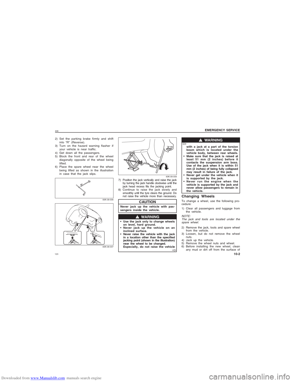
5) Block the front and rear of the wheel
diagonally opposite of the wheel being
lifted.
6) Place the spare wheel near the wheel
being lifted as shown in the illustration
in case that the jack slips.
83K-08-00683K-08-007
CAUTION
Never jack up the vehicle with pas-
sengers inside the vehicle. 7) Position the jack vertically and raise the jack
by turning the jack handle clockwise until the
jack head recess fits the jacking point.
8) Continue to raise the jack slowly and
smoothly until the tyre clears the ground. Do
not raise the vehicle more than necessary.
w ww w
w WARNING
Use the jack only to change wheels
on level, hard ground.
Never jack up the vehicle on an
inclined surface.
Never raise the vehicle with the jack
in a location other than the specified
jacking point (shown in the illustration)
near the wheel to be changed.
Especially, do not raise the vehiclewith a jack at a part of the torsion
beam which is located under the
vehicle body, between rear wheels.
Make sure that the jack is raised at
least 51 mm (2 inches) before it
contacts the suspension arm boss.
Use of the jack when it is within 51
mm (2 inches) of being fully collapsed
may result in failure of the jack.
Never get under the vehicle when it
is supported by the jack.
Never run the engine when the
vehicle is supported by the jack and
never allow passengers to remain in
the vehicle.
V VV V
V
w ww w
w WARNING
V VV V
V
Changing WheelsTo change a wheel, use the following pro-
cedure:
1) Clear all passengers and luggage from
the vehicle.NOTE:
The jack and tools are located under the
spare wheel.2) Remove the jack, tools and spare wheel
from the vehicle.
3) Loosen, but do not remove the wheel
nuts.
4) Jack up the vehicle.
5) Remove the wheel nuts and wheel.
6) Before installing the new wheel, clean
any mud or dirt off from the surface of
83K-08-008