clock SUZUKI MARUTI 2005 1.G Owners Manual
[x] Cancel search | Manufacturer: SUZUKI, Model Year: 2005, Model line: MARUTI, Model: SUZUKI MARUTI 2005 1.GPages: 136, PDF Size: 2.93 MB
Page 14 of 136
Downloaded from www.Manualslib.com manuals search engine 1483K
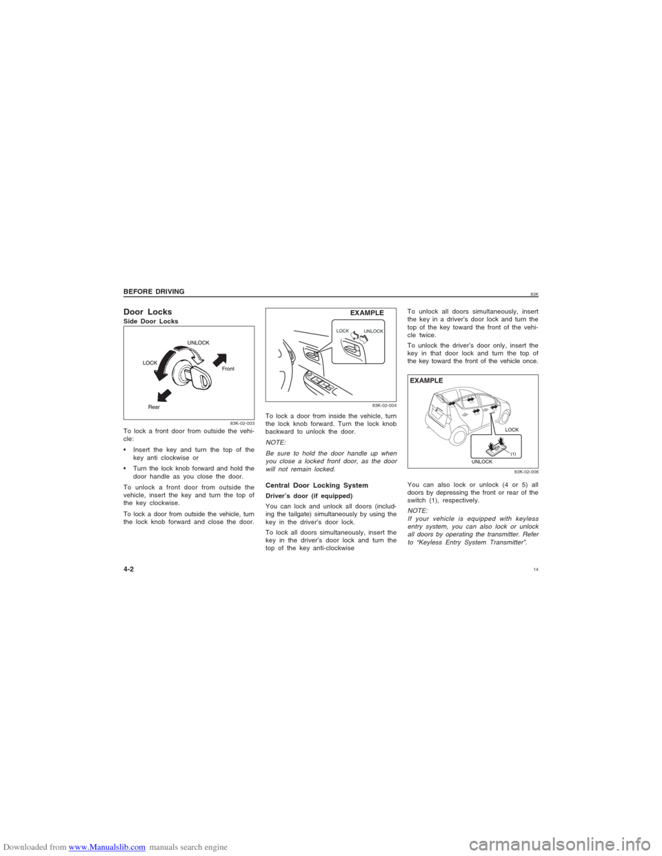
Door LocksSide Door Locks
To lock a door from inside the vehicle, turn
the lock knob forward. Turn the lock knob
backward to unlock the door.
NOTE:
Be sure to hold the door handle up when
you close a locked front door, as the door
will not remain locked.
EXAMPLE BEFORE DRIVING
4-2
83K-02-003
To lock a front door from outside the vehi-
cle:
Insert the key and turn the top of the
key anti clockwise or
Turn the lock knob forward and hold the
door handle as you close the door.
To unlock a front door from outside the
vehicle, insert the key and turn the top of
the key clockwise.
To lock a door from outside the vehicle, turn
the lock knob forward and close the door.
83K-02-004
Central Door Locking SystemDriver’s door (if equipped)
You can lock and unlock all doors (includ-
ing the tailgate) simultaneously by using the
key in the driver’s door lock.
To lock all doors simultaneously, insert the
key in the driver’s door lock and turn the
top of the key anti-clockwiseTo unlock all doors simultaneously, insert
the key in a driver’s door lock and turn the
top of the key toward the front of the vehi-
cle twice.
To unlock the driver’s door only, insert the
key in that door lock and turn the top of
the key toward the front of the vehicle once.
You can also lock or unlock (4 or 5) all
doors by depressing the front or rear of the
switch (1), respectively.
NOTE:
If your vehicle is equipped with keyless
entry system, you can also lock or unlock
all doors by operating the transmitter. Refer
to “Keyless Entry System Transmitter”.
83K-02-006
EXAMPLE
Page 15 of 136
Downloaded from www.Manualslib.com manuals search engine 1583KNOTE:
Individual doors can also be UNLOCKED
anytime by using their respective "Door
Lock Knob" inside the vehicle.
If child proof locks are in locked position,
rear doors cannot be opened from inside.
w ww w
w WARNING
Be sure to place the child-proof lock
in the locked position whenever chil-
dren are seated in the rear.
BEFORE DRIVING
4-3
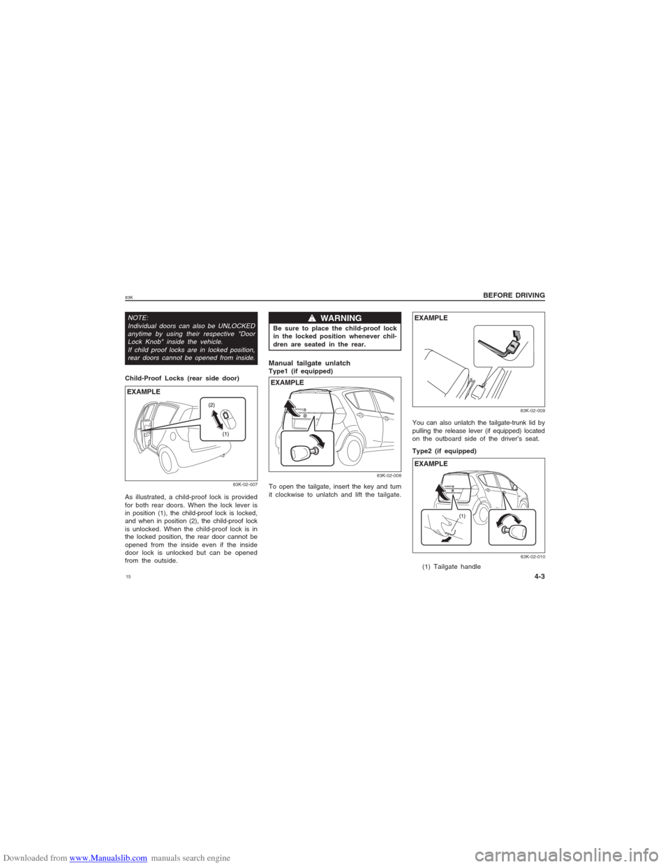
Child-Proof Locks (rear side door)
83K-02-007
EXAMPLEAs illustrated, a child-proof lock is provided
for both rear doors. When the lock lever is
in position (1), the child-proof lock is locked,
and when in position (2), the child-proof lock
is unlocked. When the child-proof lock is in
the locked position, the rear door cannot be
opened from the inside even if the inside
door lock is unlocked but can be opened
from the outside.
Manual tailgate unlatchType1 (if equipped)
83K-02-008
EXAMPLETo open the tailgate, insert the key and turn
it clockwise to unlatch and lift the tailgate.You can also unlatch the tailgate-trunk lid by
pulling the release lever (if equipped) located
on the outboard side of the driver’s seat.
Type2 (if equipped)
83K-02-00983K-02-010
EXAMPLE
EXAMPLE(1) Tailgate handle
Page 40 of 136
Downloaded from www.Manualslib.com manuals search engine 4083K
BEFORE DRIVING
4-28
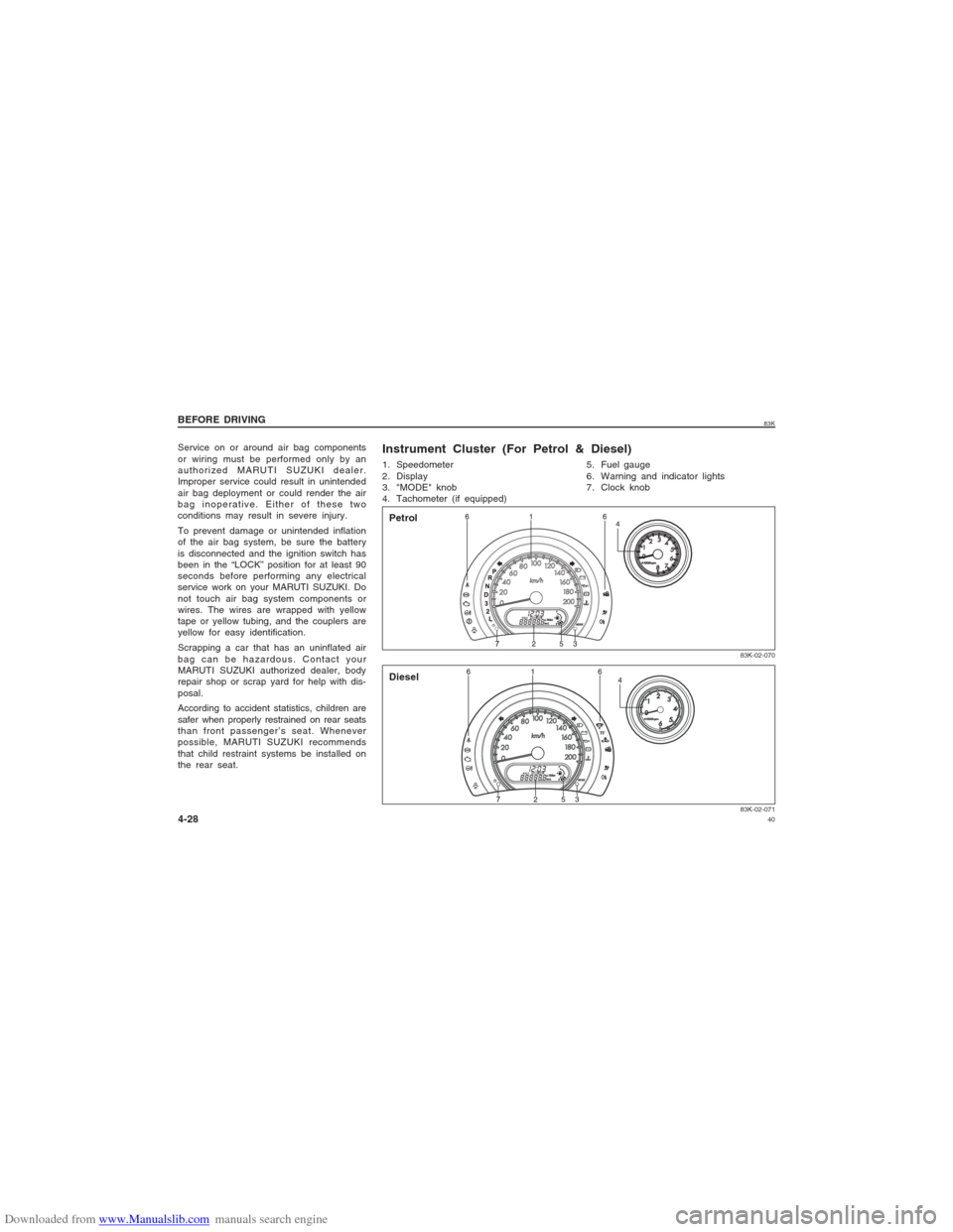
1. Speedometer
2. Display
3. "MODE" knob
4. Tachometer (if equipped)
83K-02-07183K-02-070
5. Fuel gauge
6. Warning and indicator lights
7. Clock knob
Instrument Cluster (For Petrol & Diesel)Petrol
Diesel
Service on or around air bag components
or wiring must be performed only by an
authorized MARUTI SUZUKI dealer.
Improper service could result in unintended
air bag deployment or could render the air
bag inoperative. Either of these two
conditions may result in severe injury.
To prevent damage or unintended inflation
of the air bag system, be sure the battery
is disconnected and the ignition switch has
been in the “LOCK” position for at least 90
seconds before performing any electrical
service work on your MARUTI SUZUKI. Do
not touch air bag system components or
wires. The wires are wrapped with yellow
tape or yellow tubing, and the couplers are
yellow for easy identification.
Scrapping a car that has an uninflated air
bag can be hazardous. Contact your
MARUTI SUZUKI authorized dealer, body
repair shop or scrap yard for help with dis-
posal.
According to accident statistics, children are
safer when properly restrained on rear seats
than front passenger’s seat. Whenever
possible, MARUTI SUZUKI recommends
that child restraint systems be installed on
the rear seat.
Page 48 of 136
Downloaded from www.Manualslib.com manuals search engine 4883K
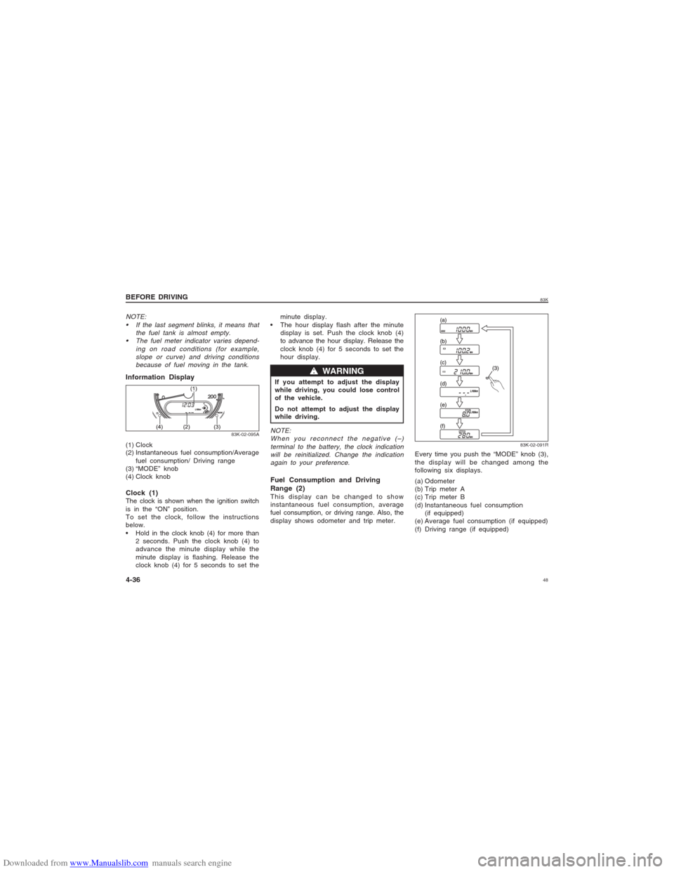
Information Display(1) Clock
(2) Instantaneous fuel consumption/Average
fuel consumption/ Driving range
(3) “MODE” knob
(4) Clock knob
83K-02-095A
NOTE:
If the last segment blinks, it means that
the fuel tank is almost empty.
The fuel meter indicator varies depend-
ing on road conditions (for example,
slope or curve) and driving conditions
because of fuel moving in the tank.Clock (1)The clock is shown when the ignition switch
is in the “ON” position.
To set the clock, follow the instructions
below.
Hold in the clock knob (4) for more than
2 seconds. Push the clock knob (4) to
advance the minute display while the
minute display is flashing. Release the
clock knob (4) for 5 seconds to set theminute display.
The hour display flash after the minute
display is set. Push the clock knob (4)
to advance the hour display. Release the
clock knob (4) for 5 seconds to set the
hour display.
If you attempt to adjust the display
while driving, you could lose control
of the vehicle.
Do not attempt to adjust the display
while driving.
w ww w
w WARNING
NOTE:
When you reconnect the negative (–)
terminal to the battery, the clock indication
will be reinitialized. Change the indication
again to your preference.Fuel Consumption and Driving
Range (2)This display can be changed to show
instantaneous fuel consumption, average
fuel consumption, or driving range. Also, the
display shows odometer and trip meter.
83K-02-091R
Every time you push the “MODE” knob (3),
the display will be changed among the
following six displays.
(a) Odometer
(b) Trip meter A
(c) Trip meter B
(d) Instantaneous fuel consumption
(if equipped)
(e) Average fuel consumption (if equipped)
(f) Driving range (if equipped)
BEFORE DRIVING
4-36
Page 58 of 136
Downloaded from www.Manualslib.com manuals search engine 5883K
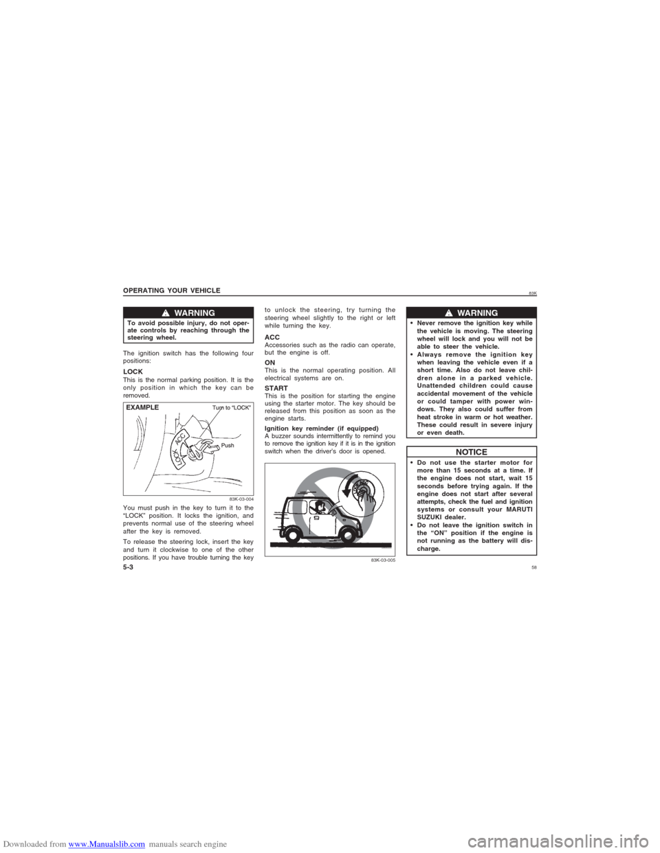
w ww w
w WARNING
To avoid possible injury, do not oper-
ate controls by reaching through the
steering wheel.
83K-03-004
EXAMPLE OPERATING YOUR VEHICLE
5-3The ignition switch has the following four
positions:LOCKThis is the normal parking position. It is the
only position in which the key can be
removed.
You must push in the key to turn it to the
“LOCK” position. It locks the ignition, and
prevents normal use of the steering wheel
after the key is removed.
To release the steering lock, insert the key
and turn it clockwise to one of the other
positions. If you have trouble turning the keyto unlock the steering, try turning the
steering wheel slightly to the right or left
while turning the key.
ACCAccessories such as the radio can operate,
but the engine is off.ONThis is the normal operating position. All
electrical systems are on.STARTThis is the position for starting the engine
using the starter motor. The key should be
released from this position as soon as the
engine starts.
Ignition key reminder (if equipped)
A buzzer sounds intermittently to remind you
to remove the ignition key if it is in the ignition
switch when the driver’s door is opened.
w ww w
w WARNING
Never remove the ignition key while
the vehicle is moving. The steering
wheel will lock and you will not be
able to steer the vehicle.
Always remove the ignition key
when leaving the vehicle even if a
short time. Also do not leave chil-
dren alone in a parked vehicle.
Unattended children could cause
accidental movement of the vehicle
or could tamper with power win-
dows. They also could suffer from
heat stroke in warm or hot weather.
These could result in severe injury
or even death.
NOTICE
Do not use the starter motor for
more than 15 seconds at a time. If
the engine does not start, wait 15
seconds before trying again. If the
engine does not start after several
attempts, check the fuel and ignition
systems or consult your MARUTI
SUZUKI dealer.
Do not leave the ignition switch in
the “ON” position if the engine is
not running as the battery will dis-
charge.
83K-03-005
Page 78 of 136
Downloaded from www.Manualslib.com manuals search engine 7883K
OTHER CONTROLS AND EQUIPMENT
7-4Using the wrong refrigerant may
damage your air conditioning system.
Use R-134a only. Do not mix or replace
the R-134a with other refrigerants.
CAUTION
NOTE:
If you need maximum demisting:
set the air flow selector to “DEMIST”,
set the blower speed selector to HIGH,
adjust the temperature selector to the
HOT end,
turn on the “A/C” switch, and
adjust the side outlets so the air blows
on the side windows.MaintenanceIf you do not use the air conditioner for a
long period, such as during winter, it may
not give the best performance when you
start using it again. To help maintain opti-
mum performance and durability of your air
conditioner, it needs to be run periodically.
Operate the air conditioner at least once a
month for one minute with the engine idling.
This circulates the refrigerant and oil and
helps protect the internal components.NOTE:
Your vehicle uses the air conditioning
refrigerant HFC-134a, commonly called “R-
134a”. Only R-134a should be used in your
vehicle.
Audio System (if equipped)Refer supplementary manual for audio
system (if equipped), provided along with
the vehicle.Radio Antenna
83K-05-013
To avoid damage to the radio antenna:
Remove the antenna when using an
automatic car wash.
Remove the antenna when the
antenna hits anything such as a low
ceiling in a parking garage or
putting a car cover over your car.
CAUTION
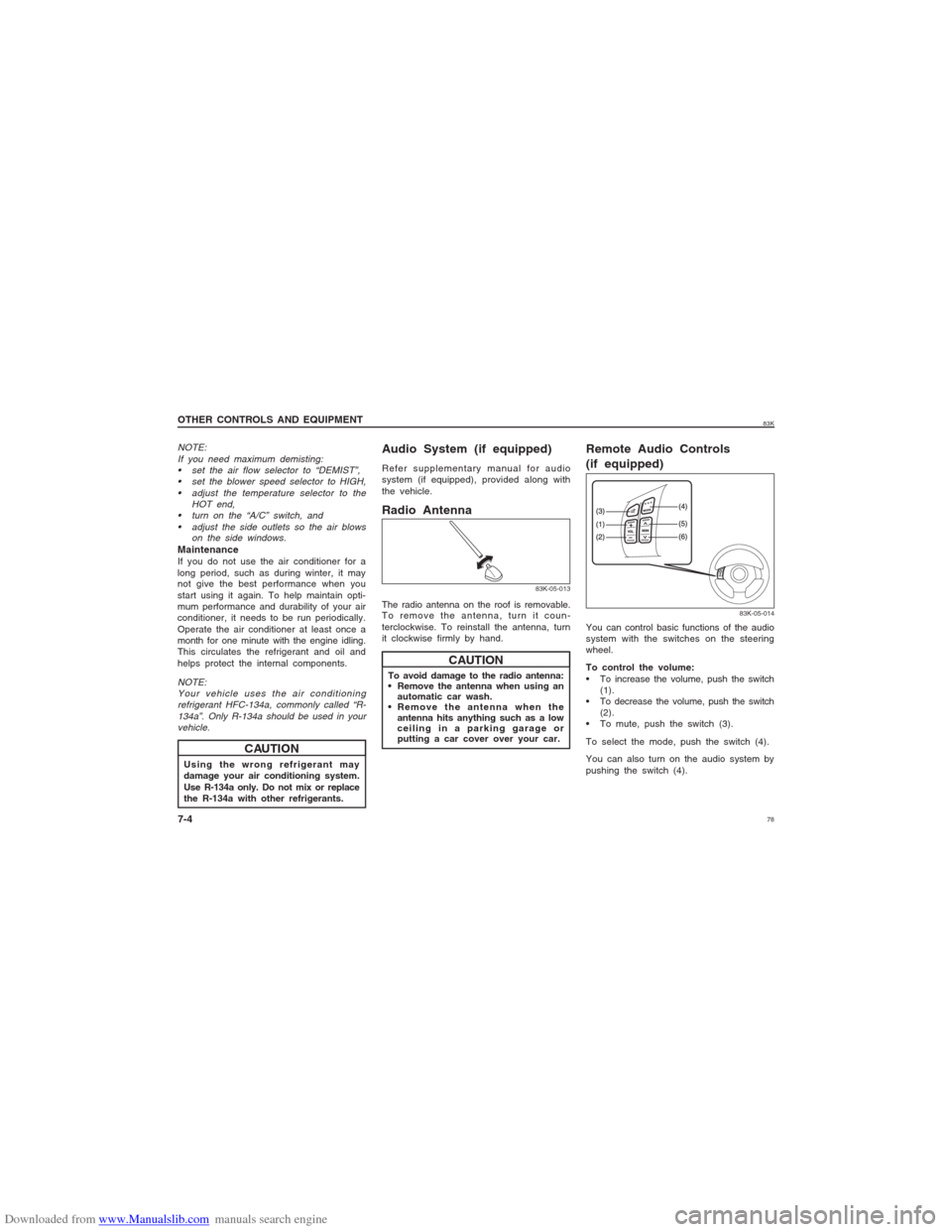
Remote Audio Controls
(if equipped)
83K-05-014
You can control basic functions of the audio
system with the switches on the steering
wheel.
To control the volume:
To increase the volume, push the switch
(1).
To decrease the volume, push the switch
(2).
To mute, push the switch (3).
To select the mode, push the switch (4).
You can also turn on the audio system by
pushing the switch (4). The radio antenna on the roof is removable.
To remove the antenna, turn it coun-
terclockwise. To reinstall the antenna, turn
it clockwise firmly by hand.
Page 79 of 136
Downloaded from www.Manualslib.com manuals search engine 7983K
OTHER CONTROLS AND EQUIPMENT
7-5
To change the radio station:
To advance to the next preset station,
push the switch (5) briefly.
To select the previous preset station,
push the switch (6) briefly.
To scan the higher frequency radio sta-
tion, push and hold the switch (5).
To scan the lower frequency radio sta-
tion, push and hold the switch (6).
To scan the selection on a CD:
To advance to the next track on a CD,
push the switch (5).
To select the previous track on a CD,
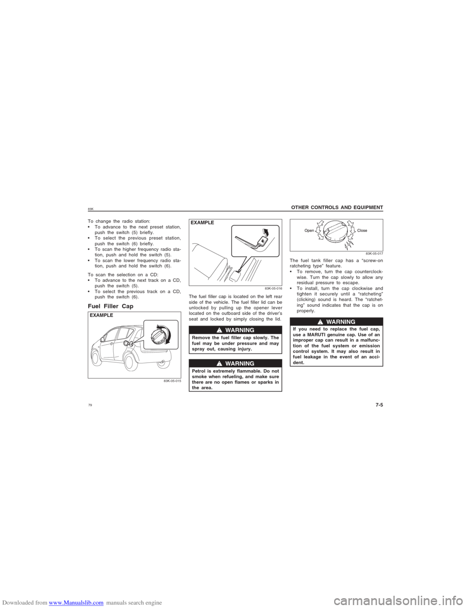
push the switch (6).Fuel Filler Cap
83K-05-015
EXAMPLE
83K-05-016
w ww w
w WARNING
Remove the fuel filler cap slowly. The
fuel may be under pressure and may
spray out, causing injury.
w ww w
w WARNING
Petrol is extremely flammable. Do not
smoke when refueling, and make sure
there are no open flames or sparks in
the area.
EXAMPLE
83K-05-017
The fuel tank filler cap has a “screw-on
ratcheting type” feature.
To remove, turn the cap counterclock-
wise. Turn the cap slowly to allow any
residual pressure to escape.
To install, turn the cap clockwise and
tighten it securely until a “ratcheting”
(clicking) sound is heard. The “ratchet-
ing” sound indicates that the cap is on
properly. The fuel filler cap is located on the left rear
side of the vehicle. The fuel filler lid can be
unlocked by pulling up the opener lever
located on the outboard side of the driver’s
seat and locked by simply closing the lid.
If you need to replace the fuel cap,
use a MARUTI genuine cap. Use of an
improper cap can result in a malfunc-
tion of the fuel system or emission
control system. It may also result in
fuel leakage in the event of an acci-
dent.
w ww w
w WARNING
Page 85 of 136
Downloaded from www.Manualslib.com manuals search engine 8583K
OTHER CONTROLS AND EQUIPMENT
7-11
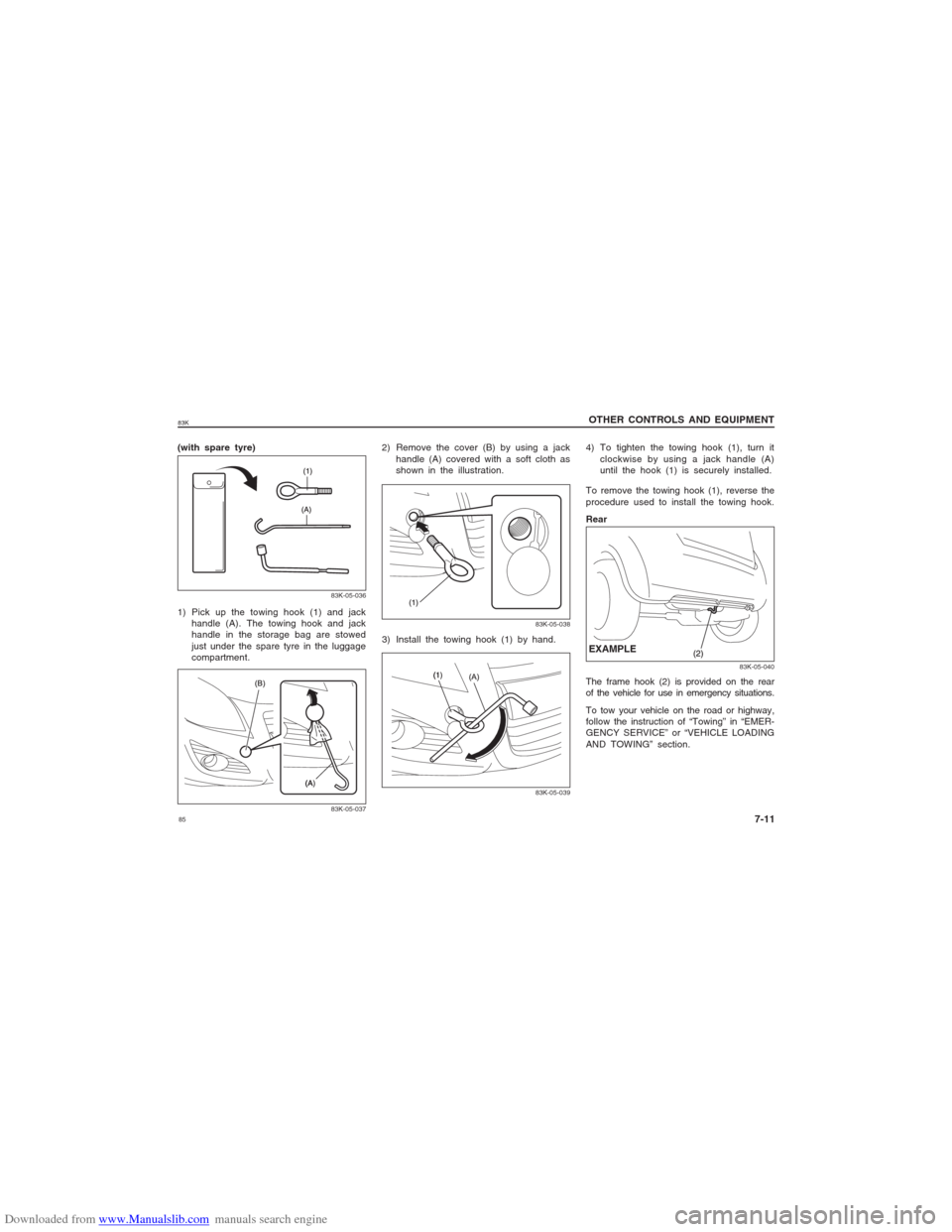
(with spare tyre)
83K-05-03683K-05-037
1) Pick up the towing hook (1) and jack
handle (A). The towing hook and jack
handle in the storage bag are stowed
just under the spare tyre in the luggage
compartment.2) Remove the cover (B) by using a jack
handle (A) covered with a soft cloth as
shown in the illustration.
83K-05-038
3) Install the towing hook (1) by hand.
83K-05-039
To remove the towing hook (1), reverse the
procedure used to install the towing hook.
Rear
83K-05-040
The frame hook (2) is provided on the rear
of the vehicle for use in emergency situations.
To tow your vehicle on the road or highway,
follow the instruction of “Towing” in “EMER-
GENCY SERVICE” or “VEHICLE LOADING
AND TOWING” section.EXAMPLE4) To tighten the towing hook (1), turn it
clockwise by using a jack handle (A)
until the hook (1) is securely installed.
Page 97 of 136
Downloaded from www.Manualslib.com manuals search engine 9783K
INSPECTION AND MAINTENANCE
9-8
83K-07-011
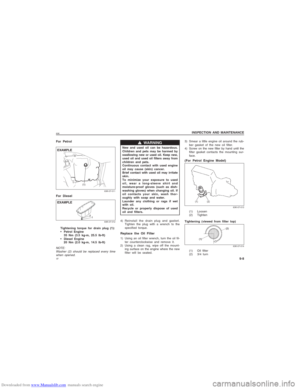
EXAMPLE For Petrol
For Diesel
EXAMPLETightening torque for drain plug (1):
Petrol Engine
35 Nm (3.5 kg-m, 25.5 lb-ft)
Diesel Engine
20 Nm (2.0 kg-m, 14.5 lb-ft)
NOTE:
Washer (2) should be replaced every time
when opened.
w ww w
w WARNING
New and used oil can be hazardous.
Children and pets may be harmed by
swallowing new or used oil. Keep new,
used oil and used oil filters away from
children and pets.
Continuous contact with used engine
oil may cause (skin) cancer.
Brief contact with used oil may irritate
skin.
To minimize your exposure to used
oil, wear a long-sleeve shirt and
moisture-proof gloves (such as dish-
washing gloves) when changing oil. If
oil contacts your skin, wash thor-
oughly with soap and water.
Launder any clothing or rags if wet
with oil.
Recycle or properly dispose of used
oil and filters.
4) Reinstall the drain plug and gasket.
Tighten the plug with a wrench to the
specified torque.Replace the Oil Filter1) Using an oil filter wrench, turn the oil fil-
ter counterclockwise and remove it.
2) Using a clean rag, wipe off the mount-
ing surface on the engine where the new
filter will be seated.3) Smear a little engine oil around the rub-
ber gasket of the new oil filter.
4) Screw on the new filter by hand until the
filter gasket contacts the mounting sur-
face.
(For Petrol Engine Model)
83K-07-012
83K-07-013
(1) Loosen
(2) Tighten
Tightening (viewed from filter top)
83K-07-014
(1) Oil filter
(2) 3/4 turn
Page 99 of 136
Downloaded from www.Manualslib.com manuals search engine 9983K
INSPECTION AND MAINTENANCE
9-10
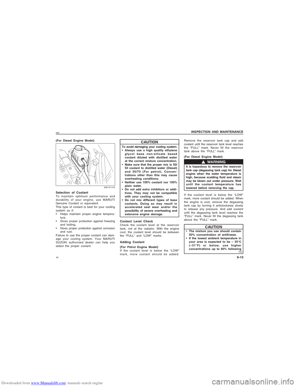
(For Diesel Engine Model)
83K-07-018
CAUTION
To avoid damaging your cooling system:
Always use a high quality ethylene
glycol base non-silicate based
coolant diluted with distilled water
at the correct mixture concentration.
Make sure that the proper mix is 50/
50 coolant to distilled water (Diesel)
and 30/70 (For petrol). Concen-
trations other than this may cause
overheating conditions.
Neither use 100% coolant nor 100%
plain water.
Do not add extra inhibitors or addi-
tives. They may not be compatible
with your cooling system.
Do not mix different types of base
coolants. Doing so may result in
accelerated seal wear and/or the
possibility of severe overheating and
extensive engine damage.Coolant Level CheckCheck the coolant level at the reservoir
tank, not at the radiator. With the engine
cool, the coolant level should be between
the “FULL” and “LOW” marks.
Selection of CoolantTo maintain optimum performance and
durability of your engine, use MARUTI
Genuine Coolant or equivalent.
This type of coolant is best for your cooling
system as it:
Helps maintain proper engine tempera-
ture.
Gives proper protection against freezing
and boiling.
Gives proper protection against corrosion
and rust.
Failure to use the proper coolant can dam-
age your cooling system. Your MARUTI
SUZUKI authorized dealer can help you
select the proper coolant.
w ww w
w WARNING
It is hazardous to remove the reservoir
tank cap (degassing tank cap) for Diesel
engine when the water temperature is
high, because scalding fluid and steam
may be blown out under pressure. Wait
until the coolant temperature has
lowered before removing the cap.
Adding Coolant(For Petrol Engine Model)
If the coolant level is below the “LOW”
mark, more coolant should be added.Remove the reservoir tank cap and add
coolant until the reservoir tank level reaches
the “FULL” mark. Never fill the reservoir
tank above the “FULL” mark.
(For Diesel Engine Model)
If the coolant level is below the “LOW”
mark, more coolant should be added. When
the engine is cool, remove the degassing
tank cap by turning it anticlockwise slowly
to release any pressure. And add coolant
until the degassing tank level reaches the
“FULL” mark. Never fill the degassing tank
above the “FULL” mark.
The mixture you use should contain
50% concentration of antifreeze.
If the lowest ambient temperature in
your area is expected to be – 35°C
(–31°F) or below, use higher
concentrations up to 60% following
CAUTION
V VV V
V