air suspension SUZUKI SWIFT 2000 1.G RG413 Service Workshop Manual
[x] Cancel search | Manufacturer: SUZUKI, Model Year: 2000, Model line: SWIFT, Model: SUZUKI SWIFT 2000 1.GPages: 698, PDF Size: 16.01 MB
Page 3 of 698
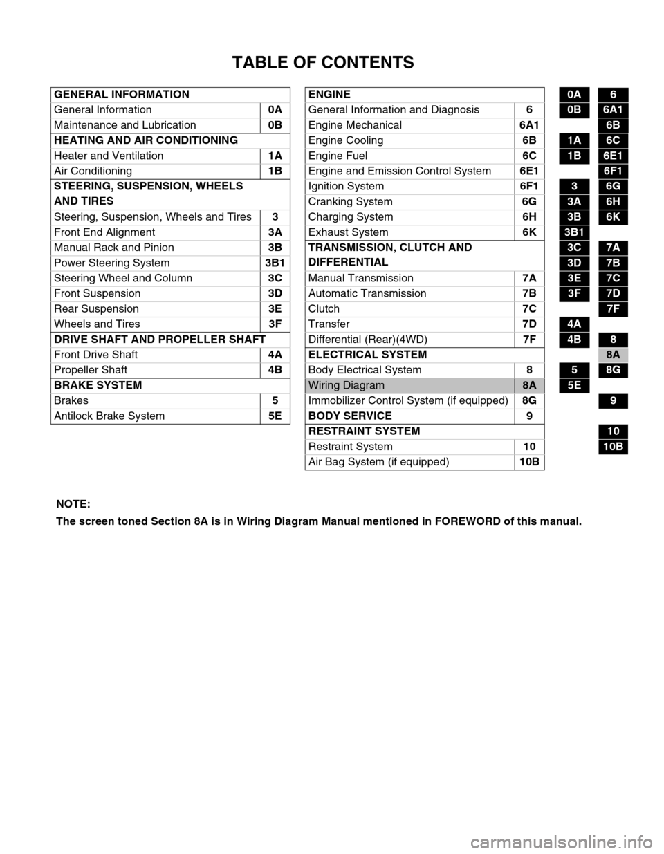
TABLE OF CONTENTS
GENERAL INFORMATION ENGINE0A6
General Information0A
General Information and Diagnosis6
0B6A1
Maintenance and Lubrication0B
Engine Mechanical6A1
6B
HEATING AND AIR CONDITIONING
Engine Cooling6B
1A6C
Heater and Ventilation1A
Engine Fuel6C
1B6E1
Air Conditioning1B
Engine and Emission Control System6E1
6F1
STEERING, SUSPENSION, WHEELS
AND TIRESIgnition System6F1
36G
Cranking System6G
3A6H
Steering, Suspension, Wheels and Tires3
Charging System6H
3B6K
Front End Alignment3A
Exhaust System6K
3B1 6B
Manual Rack and Pinion3B TRANSMISSION, CLUTCH AND
DIFFERENTIAL
3C7A
Power Steering System3B1
3D7B
Steering Wheel and Column3C
Manual Transmission7A
3E7C
Front Suspension3D
Automatic Transmission7B
3F7D
Rear Suspension3E
Clutch7C
7F
Wheels and Tires3F
Transfer7D
4A
DRIVE SHAFT AND PROPELLER SHAFT
Differential (Rear)(4WD)7F
4B8
Front Drive Shaft 4A ELECTRICAL SYSTEM
8A
Propeller Shaft4B
Body Electrical System8
58G
BRAKE SYSTEM
Wiring Diagram8A5E
Brakes5
Immobilizer Control System (if equipped)8G
9
Antilock Brake System5E BODY SERVICE 9
RESTRAINT SYSTEM
10
Restraint System10
10B
Air Bag System (if equipped)10B
NOTE:
The screen toned Section 8A is in Wiring Diagram Manual mentioned in FOREWORD of this manual.
Page 30 of 698
MAINTENANCE AND LUBRICATION 0B-1
0A 6F1
0B
0B
6G
1A 6H
1B 6K
37A
3A 7A1
3B1 7B1
3C1 7C1
3D 7D
3E 7E
3F 7F
4A2 8A
4B 8B
8C
58D
5A 8E
5B
5C 9
5E
5E1 10
10A
610B
6-1
6A1
6A2
6A4
6B
6C
6E1
6E2
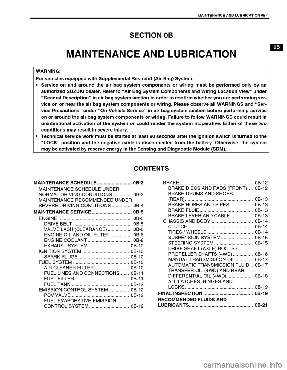
SECTION 0B
MAINTENANCE AND LUBRICATION
CONTENTS
MAINTENANCE SCHEDULE .......................... 0B-2
MAINTENANCE SCHEDULE UNDER
NORMAL DRIVING CONDITIONS .............. 0B-2
MAINTENANCE RECOMMENDED UNDER
SEVERE DRIVING CONDITIONS ............... 0B-4
MAINTENANCE SERVICE .............................. 0B-5
ENGINE ....................................................... 0B-5
DRIVE BELT ............................................ 0B-5
VALVE LASH (CLEARANCE) .................. 0B-6
ENGINE OIL AND OIL FILTER ................ 0B-6
ENGINE COOLANT ................................. 0B-8
EXHAUST SYSTEM............................... 0B-10
IGNITION SYSTEM ................................... 0B-10
SPARK PLUGS ...................................... 0B-10
FUEL SYSTEM .......................................... 0B-10
AIR CLEANER FILTER .......................... 0B-10
FUEL LINES AND CONNECTIONS....... 0B-11
FUEL FILTER ......................................... 0B-11
FUEL TANK............................................ 0B-12
EMISSION CONTROL SYSTEM ............... 0B-12
PCV VALVE ........................................... 0B-12
FUEL EVAPORATIVE EMISSION
CONTROL SYSTEM .............................. 0B-12BRAKE ....................................................... 0B-12
BRAKE DISCS AND PADS (FRONT) .... 0B-12
BRAKE DRUMS AND SHOES
(REAR) ................................................... 0B-13
BRAKE HOSES AND PIPES ................. 0B-13
BRAKE FLUID........................................ 0B-13
BRAKE LEVER AND CABLE ................. 0B-13
CHASSIS AND BODY ............................... 0B-14
CLUTCH................................................. 0B-14
TIRES / WHEELS .................................. 0B-14
SUSPENSION SYSTEM ........................ 0B-15
STEERING SYSTEM ............................. 0B-15
DRIVE SHAFT (AXLE) BOOTS /
PROPELLER SHAFTS (4WD) ............... 0B-16
MANUAL TRANSMISSION OIL ............. 0B-17
AUTOMATIC TRANSMISSION FLUID .. 0B-17
TRANSFER OIL (4WD) AND REAR
DIFFERENTIAL OIL (4WD) ................... 0B-18
ALL LATCHES, HINGES AND
LOCKS ................................................... 0B-19
FINAL INSPECTION ..................................... 0B-19
RECOMMENDED FLUIDS AND
LUBRICANTS................................................ 0B-21
WARNING:
For vehicles equipped with Supplemental Restraint (Air Bag) System:
Service on and around the air bag system components or wiring must be performed only by an
authorized SUZUKI dealer. Refer to “Air Bag System Components and Wiring Location View” under
“General Description” in air bag system section in order to confirm whether you are performing ser-
vice on or near the air bag system components or wiring. Please observe all WARNINGS and “Ser-
vice Precautions” under “On-Vehicle Service” in air bag system section before performing service
on or around the air bag system components or wiring. Failure to follow WARNINGS could result in
unintentional activation of the system or could render the system inoperative. Either of these two
conditions may result in severe injury.
Technical service work must be started at least 90 seconds after the ignition switch is turned to the
“LOCK” position and the negative cable is disconnected from the battery. Otherwise, the system
may be activated by reserve energy in the Sensing and Diagnostic Module (SDM).
Page 44 of 698
MAINTENANCE AND LUBRICATION 0B-15
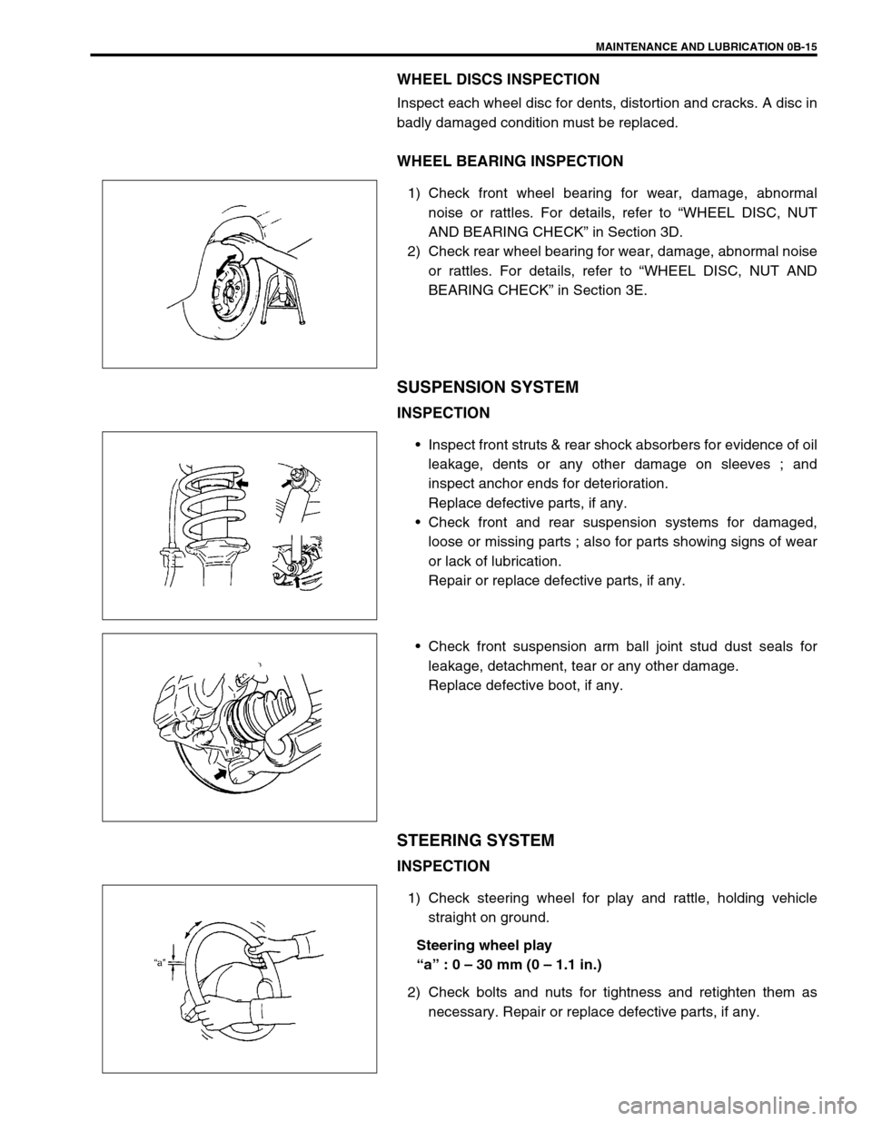
WHEEL DISCS INSPECTION
Inspect each wheel disc for dents, distortion and cracks. A disc in
badly damaged condition must be replaced.
WHEEL BEARING INSPECTION
1) Check front wheel bearing for wear, damage, abnormal
noise or rattles. For details, refer to “WHEEL DISC, NUT
AND BEARING CHECK” in Section 3D.
2) Check rear wheel bearing for wear, damage, abnormal noise
or rattles. For details, refer to “WHEEL DISC, NUT AND
BEARING CHECK” in Section 3E.
SUSPENSION SYSTEM
INSPECTION
Inspect front struts & rear shock absorbers for evidence of oil
leakage, dents or any other damage on sleeves ; and
inspect anchor ends for deterioration.
Replace defective parts, if any.
Check front and rear suspension systems for damaged,
loose or missing parts ; also for parts showing signs of wear
or lack of lubrication.
Repair or replace defective parts, if any.
Check front suspension arm ball joint stud dust seals for
leakage, detachment, tear or any other damage.
Replace defective boot, if any.
STEERING SYSTEM
INSPECTION
1) Check steering wheel for play and rattle, holding vehicle
straight on ground.
Steering wheel play
“a” : 0 – 30 mm (0 – 1.1 in.)
2) Check bolts and nuts for tightness and retighten them as
necessary. Repair or replace defective parts, if any.
Page 111 of 698
3-2 STEERING, SUSPENSION, WHEELS AND TIRES
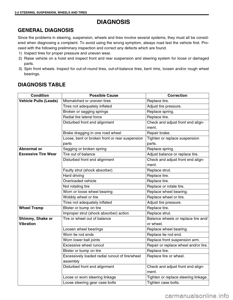
DIAGNOSIS
GENERAL DIAGNOSIS
Since the problems in steering, suspension, wheels and tires involve several systems, they must all be consid-
ered when diagnosing a complaint. To avoid using the wrong symptom, always road test the vehicle first. Pro-
ceed with the following preliminary inspection and correct any defects which are found.
1) Inspect tires for proper pressure and uneven wear.
2) Raise vehicle on a hoist and inspect front and rear suspension and steering system for loose or damaged
parts.
3) Spin front wheels. Inspect for out-of-round tires, out-of-balance tires, bent rims, loosen and/or rough wheel
bearings.
DIAGNOSIS TABLE
Condition Possible Cause Correction
Vehicle Pulls (Leads)
Mismatched or uneven tires Replace tire.
Tires not adequately inflated Adjust tire pressure.
Broken or sagging springs Replace spring.
Radial tire lateral force Replace tire.
Disturbed front end alignment Check and adjust front end align-
ment.
Brake dragging in one road wheel Repair brake.
Loose, bent or broken front or rear suspension
partsTighten or replace suspension
parts.
Abnormal or
Excessive Tire WearSagging or broken spring Replace spring.
Tire out of balance Adjust balance or replace tire.
Disturbed front end alignment Check and adjust front end align-
ment.
Faulty strut (shock absorber) Replace strut.
Hard driving Replace tire.
Overloaded vehicle Replace tire.
Not rotating tire Replace or rotate tire.
Worn or loose wheel bearing Replace wheel bearing.
Wobbly wheel or tire Replace wheel or tire.
Tires not adequately inflated Adjust tire pressure.
Wheel Tramp
Blister or bump on tire Replace tire.
Improper strut (shock absorber) action Replace strut.
Shimmy, Shake or
VibrationTire or wheel out of balance Balance wheels or replace tire and/
or wheel.
Loosen wheel bearings Replace wheel bearing.
Worn tie rod ends Replace tie rod end.
Worn lower ball joints Replace front suspension arm.
Excessive wheel runout Repair or replace wheel and/or tire.
Blister or bump on tire Replace tire.
Excessively loaded radial runout of tire/wheel
assemblyReplace tire or wheel.
Disturbed front end alignment Check and adjust front end align-
ment.
Loose or worn steering linkage Tighten or replace steering linkage.
Loose steering gear case bolts Tighten case bolts.
Page 112 of 698
STEERING, SUSPENSION, WHEELS AND TIRES 3-3
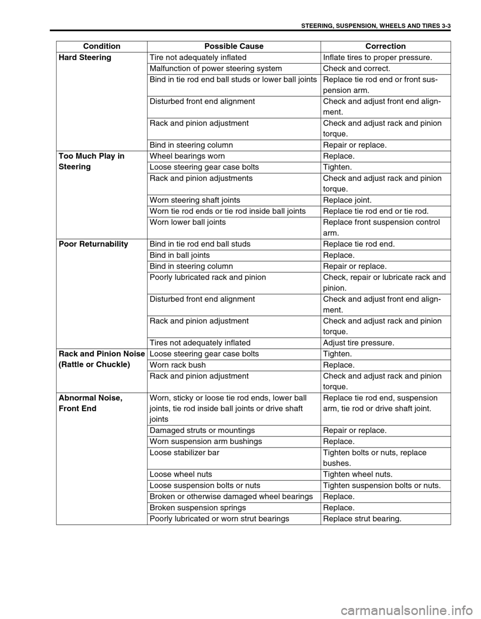
Hard Steering
Tire not adequately inflated Inflate tires to proper pressure.
Malfunction of power steering system Check and correct.
Bind in tie rod end ball studs or lower ball joints Replace tie rod end or front sus-
pension arm.
Disturbed front end alignment Check and adjust front end align-
ment.
Rack and pinion adjustment Check and adjust rack and pinion
torque.
Bind in steering column Repair or replace.
Too Much Play in
SteeringWheel bearings worn Replace.
Loose steering gear case bolts Tighten.
Rack and pinion adjustments Check and adjust rack and pinion
torque.
Worn steering shaft joints Replace joint.
Worn tie rod ends or tie rod inside ball joints Replace tie rod end or tie rod.
Worn lower ball joints Replace front suspension control
arm.
Poor Returnability
Bind in tie rod end ball studs Replace tie rod end.
Bind in ball joints Replace.
Bind in steering column Repair or replace.
Poorly lubricated rack and pinion Check, repair or lubricate rack and
pinion.
Disturbed front end alignment Check and adjust front end align-
ment.
Rack and pinion adjustment Check and adjust rack and pinion
torque.
Tires not adequately inflated Adjust tire pressure.
Rack and Pinion Noise
(Rattle or Chuckle)Loose steering gear case bolts Tighten.
Worn rack bush Replace.
Rack and pinion adjustment Check and adjust rack and pinion
torque.
Abnormal Noise,
Front EndWorn, sticky or loose tie rod ends, lower ball
joints, tie rod inside ball joints or drive shaft
jointsReplace tie rod end, suspension
arm, tie rod or drive shaft joint.
Damaged struts or mountings Repair or replace.
Worn suspension arm bushings Replace.
Loose stabilizer bar Tighten bolts or nuts, replace
bushes.
Loose wheel nuts Tighten wheel nuts.
Loose suspension bolts or nuts Tighten suspension bolts or nuts.
Broken or otherwise damaged wheel bearings Replace.
Broken suspension springs Replace.
Poorly lubricated or worn strut bearings Replace strut bearing. Condition Possible Cause Correction
Page 113 of 698
3-4 STEERING, SUSPENSION, WHEELS AND TIRES
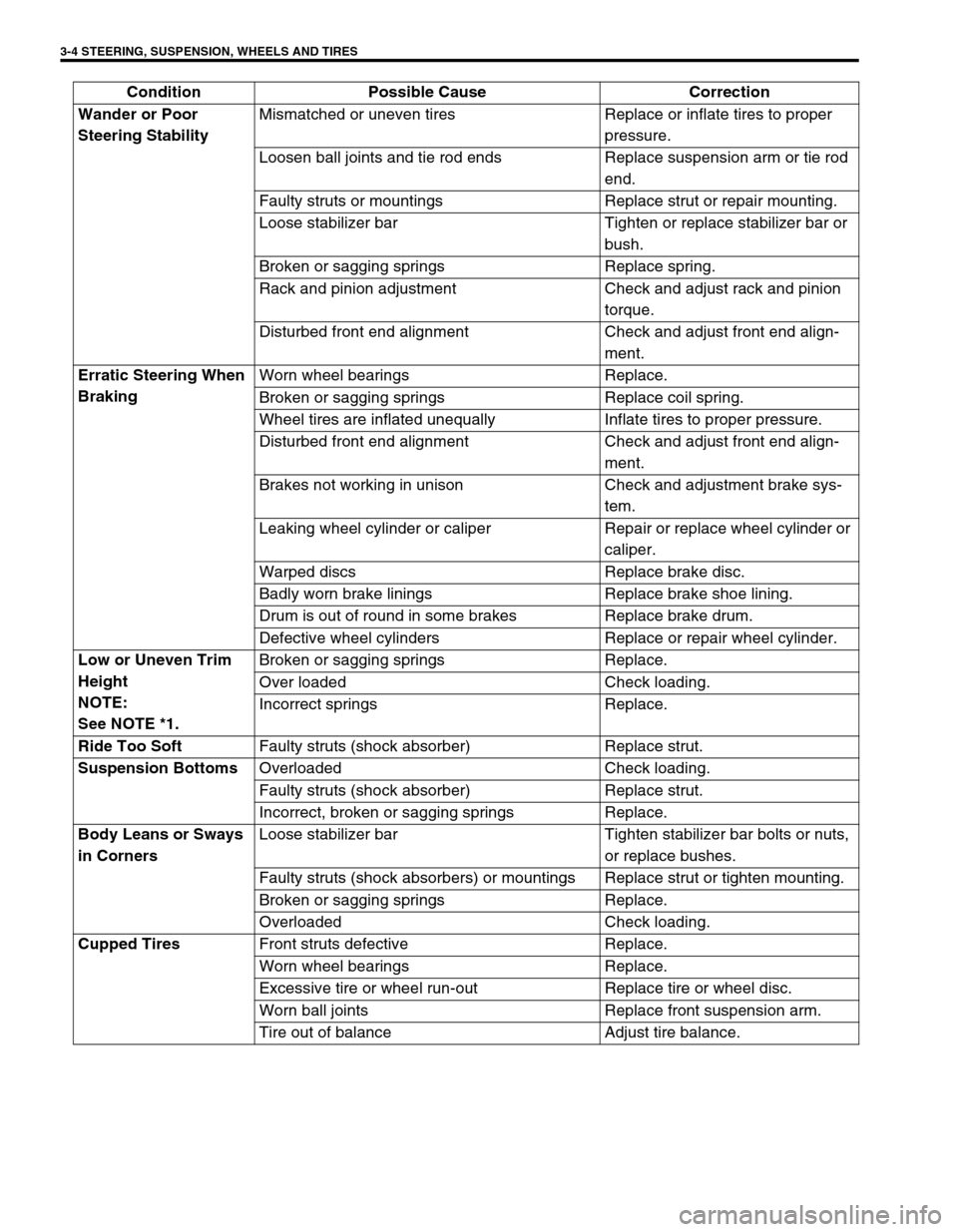
Wander or Poor
Steering StabilityMismatched or uneven tires Replace or inflate tires to proper
pressure.
Loosen ball joints and tie rod ends Replace suspension arm or tie rod
end.
Faulty struts or mountings Replace strut or repair mounting.
Loose stabilizer bar Tighten or replace stabilizer bar or
bush.
Broken or sagging springs Replace spring.
Rack and pinion adjustment Check and adjust rack and pinion
torque.
Disturbed front end alignment Check and adjust front end align-
ment.
Erratic Steering When
BrakingWorn wheel bearings Replace.
Broken or sagging springs Replace coil spring.
Wheel tires are inflated unequally Inflate tires to proper pressure.
Disturbed front end alignment Check and adjust front end align-
ment.
Brakes not working in unison Check and adjustment brake sys-
tem.
Leaking wheel cylinder or caliper Repair or replace wheel cylinder or
caliper.
Warped discs Replace brake disc.
Badly worn brake linings Replace brake shoe lining.
Drum is out of round in some brakes Replace brake drum.
Defective wheel cylinders Replace or repair wheel cylinder.
Low or Uneven Trim
Height
NOTE:
See NOTE *1.Broken or sagging springs Replace.
Over loaded Check loading.
Incorrect springs Replace.
Ride Too Soft
Faulty struts (shock absorber) Replace strut.
Suspension Bottoms
Overloaded Check loading.
Faulty struts (shock absorber) Replace strut.
Incorrect, broken or sagging springs Replace.
Body Leans or Sways
in CornersLoose stabilizer bar Tighten stabilizer bar bolts or nuts,
or replace bushes.
Faulty struts (shock absorbers) or mountings Replace strut or tighten mounting.
Broken or sagging springs Replace.
Overloaded Check loading.
Cupped Tires
Front struts defective Replace.
Worn wheel bearings Replace.
Excessive tire or wheel run-out Replace tire or wheel disc.
Worn ball joints Replace front suspension arm.
Tire out of balance Adjust tire balance. Condition Possible Cause Correction
Page 119 of 698
3A-2 FRONT END ALIGNMENT
GENERAL DESCRIPTION
Front alignment refers to the angular relationship between the
front wheels, the front suspension attaching parts and the ground.
Generally, the only adjustment required for front alignment is toe
setting.
Camber and caster can’t be adjusted. Therefore, should camber
or caster be out of specification due to the damage caused by
hazardous road conditions or collision, whether the damage is in
body or in suspension should be determined. If the body is dam-
aged, it should be repaired and if suspension is damaged, it
should be replaced.
TOE SETTING
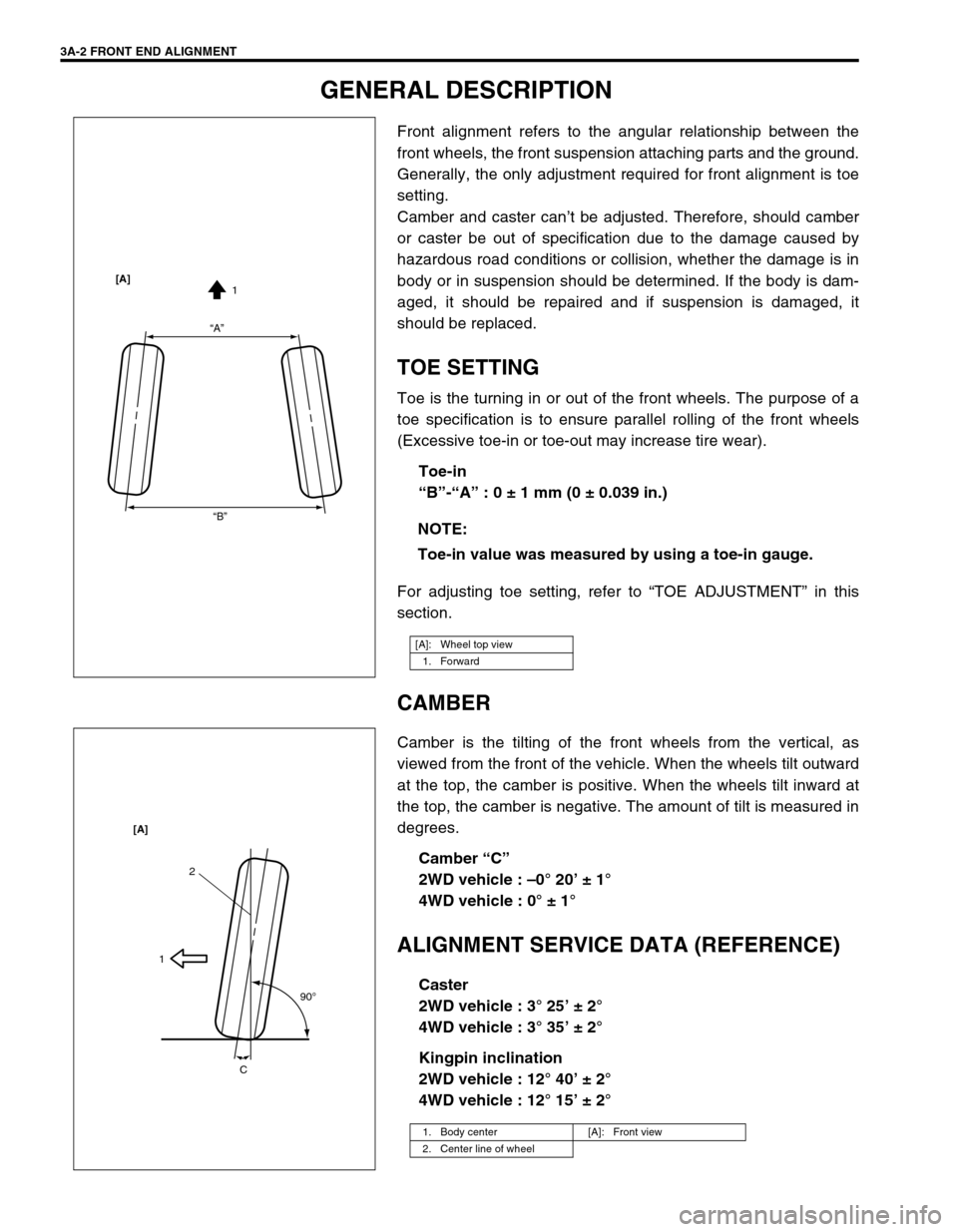
Toe is the turning in or out of the front wheels. The purpose of a
toe specification is to ensure parallel rolling of the front wheels
(Excessive toe-in or toe-out may increase tire wear).
Toe-in
“B”-“A” : 0 ± 1 mm (0 ± 0.039 in.)
For adjusting toe setting, refer to “TOE ADJUSTMENT” in this
section.
CAMBER
Camber is the tilting of the front wheels from the vertical, as
viewed from the front of the vehicle. When the wheels tilt outward
at the top, the camber is positive. When the wheels tilt inward at
the top, the camber is negative. The amount of tilt is measured in
degrees.
Camber “C”
2WD vehicle : –0° 20’ ± 1°
4WD vehicle : 0° ± 1°
ALIGNMENT SERVICE DATA (REFERENCE)
Caster
2WD vehicle : 3° 25’ ± 2°
4WD vehicle : 3° 35’ ± 2°
Kingpin inclination
2WD vehicle : 12° 40’ ± 2°
4WD vehicle : 12° 15’ ± 2° NOTE:
Toe-in value was measured by using a toe-in gauge.
[A]: Wheel top view
1. Forward
“A”
“B”1 [A]
1. Body center [A]: Front view
2. Center line of wheel
2
1
90
o
C [A]
Page 121 of 698
3A-4 FRONT END ALIGNMENT
CAMBER AND CASTER CHECK AND
ADJUSTMENT
Should camber or caster be found out of specifications upon
inspection, locate its cause first.
If it is in damaged, loose, bent, dented or worn suspension parts,
they should be replaced.
If it is in vehicle body, repair it so as to attain specifications.
STEERING ANGLE CHECK AND ADJUST-
MENT
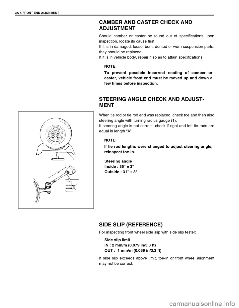
When tie rod or tie rod end was replaced, check toe and then also
steering angle with turning radius gauge (1).
If steering angle is not correct, check if right and left tie rods are
equal in length “A”.
Steering angle
Inside : 35° ± 3°
Outside : 31° ± 3°
SIDE SLIP (REFERENCE)
For inspecting front wheel side slip with side slip tester:
Side slip limit
IN : 2 mm/m (0.079 in/3.3 ft)
OUT : 1 mm/m (0.039 in/3.3 ft)
If side slip exceeds above limit, toe-in or front wheel alignment
may not be correct.NOTE:
To prevent possible incorrect reading of camber or
caster, vehicle front end must be moved up and down a
few times before inspection.
NOTE:
If tie rod lengths were changed to adjust steering angle,
reinspect toe-in.
Page 194 of 698
FRONT SUSPENSION 3D-1
6F1
6F2
6G
1A
6K
7A
7A1
7B1
7C1
3D
7F
8A
8B
8C
8D
8E
9
10
10A
10B
SECTION 3D
FRONT SUSPENSION
CONTENTS
GENERAL DESCRIPTION .............................. 3D-1
DIAGNOSIS ..................................................... 3D-3
STABILIZER BAR AND/OR BUSHING
CHECK ......................................................... 3D-3
STRUT ASSEMBLY CHECK ....................... 3D-3
SUSPENSION CONTROL ARM / STEERING
KNUCKLE CHECK ....................................... 3D-4
SUSPENSION CONTROL ARM BUSHING
CHECK ......................................................... 3D-4
SUSPENSION CONTROL ARM JOINT
CHECK ......................................................... 3D-4
FRONT SUSPENSION FASTENERS
CHECK ......................................................... 3D-5WHEEL DISC, NUT AND BEARING
CHECK ........................................................ 3D-5
ON-VEHICLE SERVICE .................................. 3D-6
STRUT ASSEMBLY..................................... 3D-6
STABILIZER BAR AND/OR BUSHINGS ..... 3D-9
WHEEL HUB AND STEERING
KNUCKLE .................................................. 3D-11
SUSPENSION CONTROL ARM /
BUSHING................................................... 3D-16
REQUIRED SERVICE MATERIAL................ 3D-19
SPECIAL TOOL ............................................ 3D-19
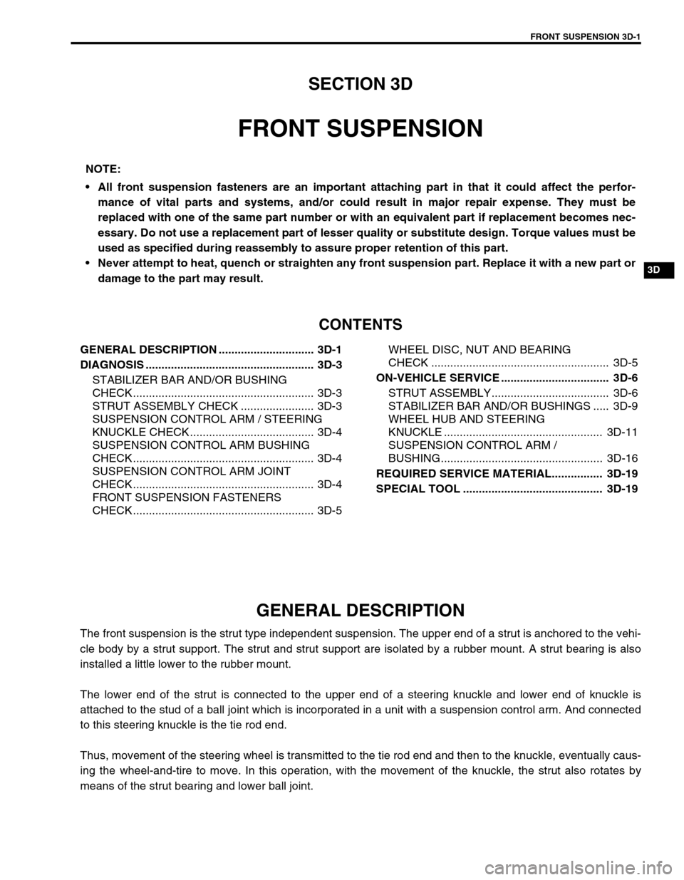
GENERAL DESCRIPTION
The front suspension is the strut type independent suspension. The upper end of a strut is anchored to the vehi-
cle body by a strut support. The strut and strut support are isolated by a rubber mount. A strut bearing is also
installed a little lower to the rubber mount.
The lower end of the strut is connected to the upper end of a steering knuckle and lower end of knuckle is
attached to the stud of a ball joint which is incorporated in a unit with a suspension control arm. And connected
to this steering knuckle is the tie rod end.
Thus, movement of the steering wheel is transmitted to the tie rod end and then to the knuckle, eventually caus-
ing the wheel-and-tire to move. In this operation, with the movement of the knuckle, the strut also rotates by
means of the strut bearing and lower ball joint.NOTE:
All front suspension fasteners are an important attaching part in that it could affect the perfor-
mance of vital parts and systems, and/or could result in major repair expense. They must be
replaced with one of the same part number or with an equivalent part if replacement becomes nec-
essary. Do not use a replacement part of lesser quality or substitute design. Torque values must be
used as specified during reassembly to assure proper retention of this part.
Never attempt to heat, quench or straighten any front suspension part. Replace it with a new part or
damage to the part may result.
Page 214 of 698
REAR SUSPENSION 3E-1
6F1
6F2
6G
1A
6K
7A
7A1
7B1
7C1
3E
8A
8B
8C
8D
8E
9
10
10A
10B
SECTION 3E
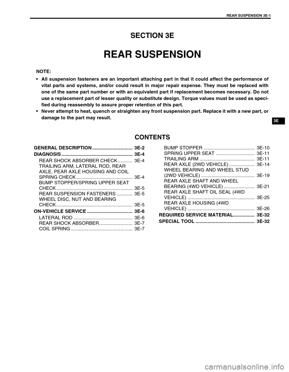
REAR SUSPENSION
CONTENTS
GENERAL DESCRIPTION .............................. 3E-2
DIAGNOSIS ..................................................... 3E-4
REAR SHOCK ABSORBER CHECK ........... 3E-4
TRAILING ARM, LATERAL ROD, REAR
AXLE, PEAR AXLE HOUSING AND COIL
SPRING CHECK .......................................... 3E-4
BUMP STOPPER/SPRING UPPER SEAT
CHECK ......................................................... 3E-5
REAR SUSPENSION FASTENERS ............ 3E-5
WHEEL DISC, NUT AND BEARING
CHECK ......................................................... 3E-5
ON-VEHICLE SERVICE .................................. 3E-6
LATERAL ROD ............................................ 3E-6
REAR SHOCK ABSORBER......................... 3E-7
COIL SPRING .............................................. 3E-7BUMP STOPPER ...................................... 3E-10
SPRING UPPER SEAT ............................. 3E-11
TRAILING ARM ......................................... 3E-11
REAR AXLE (2WD VEHICLE) ................... 3E-14
WHEEL BEARING AND WHEEL STUD
(2WD VEHICLE) ........................................ 3E-19
REAR AXLE SHAFT AND WHEEL
BEARING (4WD VEHICLE) ....................... 3E-21
REAR AXLE SHAFT OIL SEAL (4WD
VEHICLE) .................................................. 3E-25
REAR AXLE HOUSING (4WD
VEHICLE) .................................................. 3E-26
REQUIRED SERVICE MATERIAL................ 3E-32
SPECIAL TOOL ............................................ 3E-32
NOTE:
All suspension fasteners are an important attaching part in that it could affect the performance of
vital parts and systems, and/or could result in major repair expense. They must be replaced with
one of the same part number or with an equivalent part if replacement becomes necessary. Do not
use a replacement part of lesser quality or substitute design. Torque values must be used as speci-
fied during reassembly to assure proper retention of this part.
Never attempt to heat, quench or straighten any front suspension part. Replace it with a new part, or
damage to the part may result.