Fuel pump assembly SUZUKI SWIFT 2000 1.G RG413 Service User Guide
[x] Cancel search | Manufacturer: SUZUKI, Model Year: 2000, Model line: SWIFT, Model: SUZUKI SWIFT 2000 1.GPages: 698, PDF Size: 16.01 MB
Page 617 of 698
6C-10 ENGINE FUEL
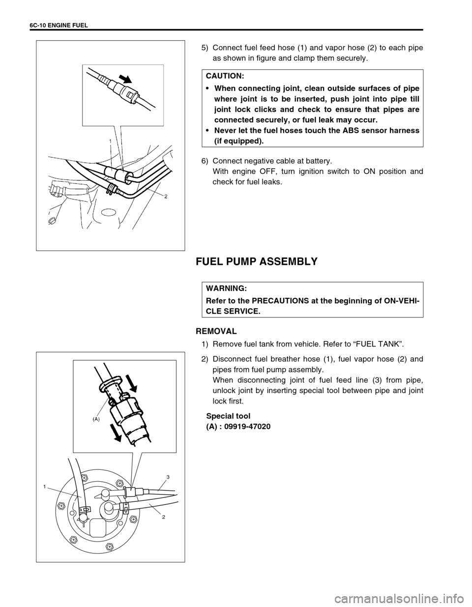
5) Connect fuel feed hose (1) and vapor hose (2) to each pipe
as shown in figure and clamp them securely.
6) Connect negative cable at battery.
With engine OFF, turn ignition switch to ON position and
check for fuel leaks.
FUEL PUMP ASSEMBLY
REMOVAL
1) Remove fuel tank from vehicle. Refer to “FUEL TANK”.
2) Disconnect fuel breather hose (1), fuel vapor hose (2) and
pipes from fuel pump assembly.
When disconnecting joint of fuel feed line (3) from pipe,
unlock joint by inserting special tool between pipe and joint
lock first.
Special tool
(A) : 09919-47020 CAUTION:
When connecting joint, clean outside surfaces of pipe
where joint is to be inserted, push joint into pipe till
joint lock clicks and check to ensure that pipes are
connected securely, or fuel leak may occur.
Never let the fuel hoses touch the ABS sensor harness
(if equipped).
WARNING:
Refer to the PRECAUTIONS at the beginning of ON-VEHI-
CLE SERVICE.
1
23
Page 618 of 698

ENGINE FUEL 6C-11
3) Remove fuel pump assembly (1) from fuel tank (2).
INSPECTION
Check fuel pump assembly for damage.
Check fuel suction filter (1) for evidence of dirt and contami-
nation.
If present, replace or clean and check for presence of dirt in
fuel tank.
For operation or electrical circuit inspection by referring to
Section 6E1.
For inspection of fuel level gauge (2) by referring to Section
8.
Check tank pressure control valve referring to the following
procedures.
a) Air should pass through valve (2) smoothly from fuel vapor
line hose (3) “A” to “B” when blown hard.
b) Also, when vacuum pump (4) is connected to fuel vapor
hose and pump air through valve, air should pass from “B”
to “A”.
Special tool
(A) : 09917-47910
If air doesn’t pass through valve in Step a) or vacuum is main-
tained in Step b), replace fuel filter assembly (1).
1
2
WARNING:
Do not such air through fuel vapor line hose. Fuel vapor
inside valve is harmful.12
Page 619 of 698
6C-12 ENGINE FUEL
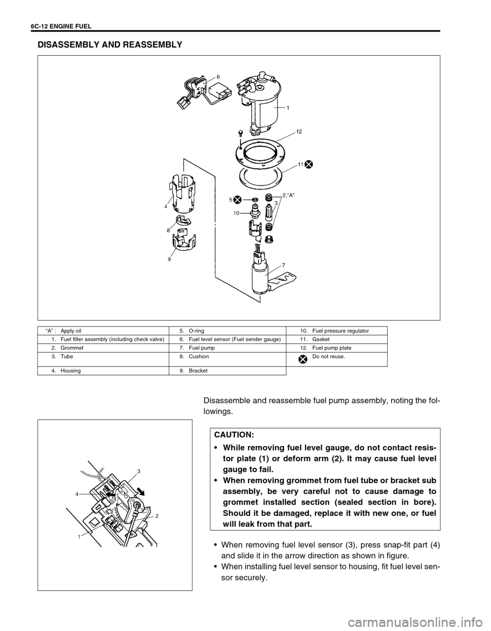
DISASSEMBLY AND REASSEMBLY
Disassemble and reassemble fuel pump assembly, noting the fol-
lowings.
When removing fuel level sensor (3), press snap-fit part (4)
and slide it in the arrow direction as shown in figure.
When installing fuel level sensor to housing, fit fuel level sen-
sor securely.
“A” : Apply oil 5. O-ring 10. Fuel pressure regulator
1. Fuel filter assembly (including check valve) 6. Fuel level sensor (Fuel sender gauge) 11. Gasket
2. Grommet 7. Fuel pump 12. Fuel pump plate
3. Tube 8. Cushion Do not reuse.
4. Housing 9. Bracket
CAUTION:
While removing fuel level gauge, do not contact resis-
tor plate (1) or deform arm (2). It may cause fuel level
gauge to fail.
When removing grommet from fuel tube or bracket sub
assembly, be very careful not to cause damage to
grommet installed section (sealed section in bore).
Should it be damaged, replace it with new one, or fuel
will leak from that part.
Page 620 of 698
ENGINE FUEL 6C-13
INSTALLATION
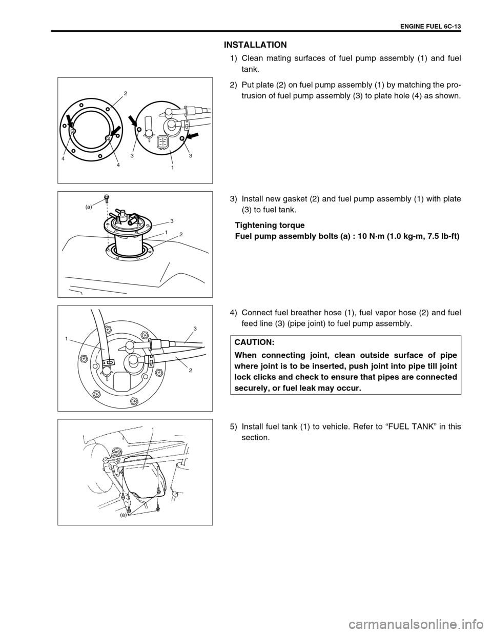
1) Clean mating surfaces of fuel pump assembly (1) and fuel
tank.
2) Put plate (2) on fuel pump assembly (1) by matching the pro-
trusion of fuel pump assembly (3) to plate hole (4) as shown.
3) Install new gasket (2) and fuel pump assembly (1) with plate
(3) to fuel tank.
Tightening torque
Fuel pump assembly bolts (a) : 10 N·m (1.0 kg-m, 7.5 lb-ft)
4) Connect fuel breather hose (1), fuel vapor hose (2) and fuel
feed line (3) (pipe joint) to fuel pump assembly.
5) Install fuel tank (1) to vehicle. Refer to “FUEL TANK” in this
section.
3 2
4 43
1
3
1
2
(a)
CAUTION:
When connecting joint, clean outside surface of pipe
where joint is to be inserted, push joint into pipe till joint
lock clicks and check to ensure that pipes are connected
securely, or fuel leak may occur.1
23
Page 621 of 698

6C-14 ENGINE FUEL
SPECIAL TOOL
TIGHTENING TORQUE SPECIFICATION
09917-47010 09919-47020
Vacuum pump gauge Quick joint remover
Fastening partTightening torque
Nm kg-m lb-ft
Fuel tank bolts 23 2.3 17
Fuel filler hose clamps 1.5 0.15 1
Fuel pump assembly bolts 10 1 7.5
Page 626 of 698
ENGINE AND EMISSION CONTROL SYSTEM 6E1-5
AIR INTAKE SYSTEM
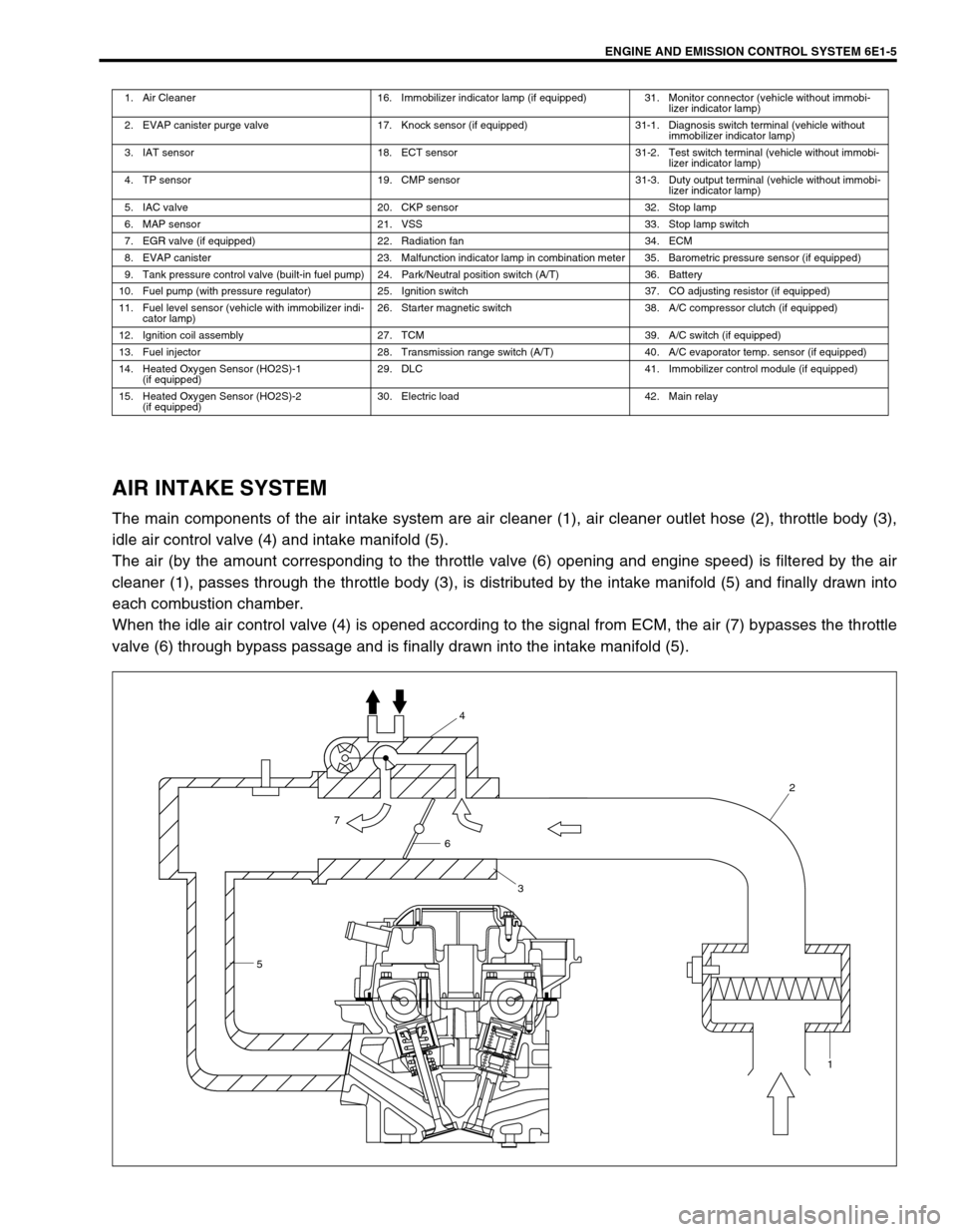
The main components of the air intake system are air cleaner (1), air cleaner outlet hose (2), throttle body (3),
idle air control valve (4) and intake manifold (5).
The air (by the amount corresponding to the throttle valve (6) opening and engine speed) is filtered by the air
cleaner (1), passes through the throttle body (3), is distributed by the intake manifold (5) and finally drawn into
each combustion chamber.
When the idle air control valve (4) is opened according to the signal from ECM, the air (7) bypasses the throttle
valve (6) through bypass passage and is finally drawn into the intake manifold (5).
1. Air Cleaner 16. Immobilizer indicator lamp (if equipped) 31. Monitor connector (vehicle without immobi-
lizer indicator lamp)
2. EVAP canister purge valve 17. Knock sensor (if equipped) 31-1. Diagnosis switch terminal (vehicle without
immobilizer indicator lamp)
3. IAT sensor 18. ECT sensor 31-2. Test switch terminal (vehicle without immobi-
lizer indicator lamp)
4. TP sensor 19. CMP sensor 31-3. Duty output terminal (vehicle without immobi-
lizer indicator lamp)
5. IAC valve 20. CKP sensor 32. Stop lamp
6. MAP sensor 21. VSS 33. Stop lamp switch
7. EGR valve (if equipped) 22. Radiation fan 34. ECM
8. EVAP canister 23. Malfunction indicator lamp in combination meter 35. Barometric pressure sensor (if equipped)
9. Tank pressure control valve (built-in fuel pump) 24. Park/Neutral position switch (A/T) 36. Battery
10. Fuel pump (with pressure regulator) 25. Ignition switch 37. CO adjusting resistor (if equipped)
11. Fuel level sensor (vehicle with immobilizer indi-
cator lamp)26. Starter magnetic switch 38. A/C compressor clutch (if equipped)
12. Ignition coil assembly 27. TCM 39. A/C switch (if equipped)
13. Fuel injector 28. Transmission range switch (A/T) 40. A/C evaporator temp. sensor (if equipped)
14. Heated Oxygen Sensor (HO2S)-1
(if equipped)29. DLC 41. Immobilizer control module (if equipped)
15. Heated Oxygen Sensor (HO2S)-2
(if equipped)30. Electric load 42. Main relay
54
2
1
6
3
7
Page 627 of 698
6E1-6 ENGINE AND EMISSION CONTROL SYSTEM
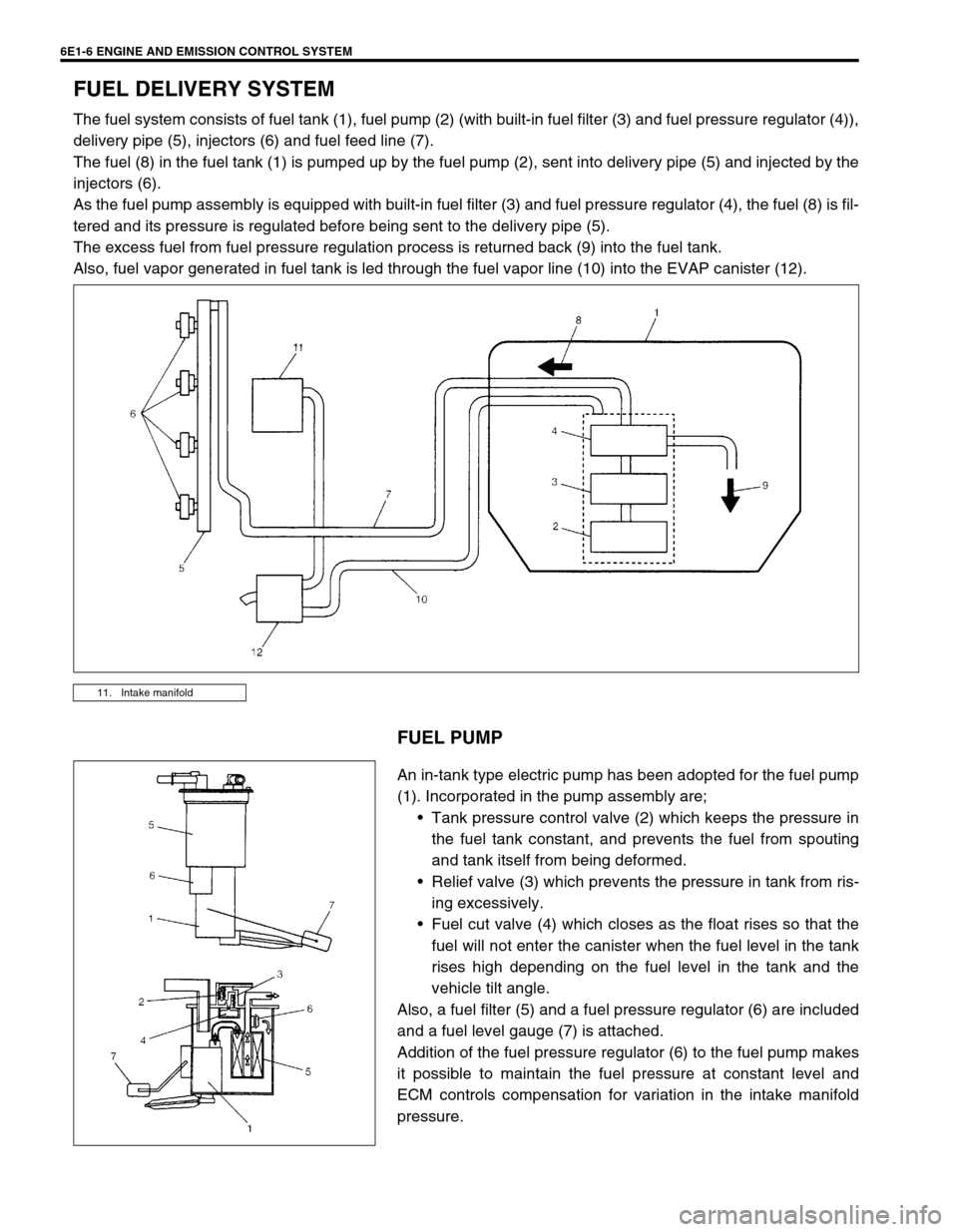
FUEL DELIVERY SYSTEM
The fuel system consists of fuel tank (1), fuel pump (2) (with built-in fuel filter (3) and fuel pressure regulator (4)),
delivery pipe (5), injectors (6) and fuel feed line (7).
The fuel (8) in the fuel tank (1) is pumped up by the fuel pump (2), sent into delivery pipe (5) and injected by the
injectors (6).
As the fuel pump assembly is equipped with built-in fuel filter (3) and fuel pressure regulator (4), the fuel (8) is fil-
tered and its pressure is regulated before being sent to the delivery pipe (5).
The excess fuel from fuel pressure regulation process is returned back (9) into the fuel tank.
Also, fuel vapor generated in fuel tank is led through the fuel vapor line (10) into the EVAP canister (12).
FUEL PUMP
An in-tank type electric pump has been adopted for the fuel pump
(1). Incorporated in the pump assembly are;
Tank pressure control valve (2) which keeps the pressure in
the fuel tank constant, and prevents the fuel from spouting
and tank itself from being deformed.
Relief valve (3) which prevents the pressure in tank from ris-
ing excessively.
Fuel cut valve (4) which closes as the float rises so that the
fuel will not enter the canister when the fuel level in the tank
rises high depending on the fuel level in the tank and the
vehicle tilt angle.
Also, a fuel filter (5) and a fuel pressure regulator (6) are included
and a fuel level gauge (7) is attached.
Addition of the fuel pressure regulator (6) to the fuel pump makes
it possible to maintain the fuel pressure at constant level and
ECM controls compensation for variation in the intake manifold
pressure.
11. Intake manifold
Page 628 of 698

ENGINE AND EMISSION CONTROL SYSTEM 6E1-7
ELECTRONIC CONTROL SYSTEM
The electronic control system consists of 1) various sensors which detect the state of engine and driving condi-
tions, 2) ECM which controls various devices according to the signals from the sensors and 3) various controlled
devices.
Functionally, it is divided into nine sub systems :
Fuel injection control system
Idle speed control system
Fuel pump control system
A/C control system (if equipped)
Radiator fan control system
EGR system (if equipped)
Evaporative emission control system
Oxygen sensor heater control system (if equipped)
Ignition control system
Also, with A/T model, ECM sends throttle valve opening signal and coolant temp. signal to transmission control
module to control A/T.
INFORMATION SENSORS CONTROL DEVICES OTHERS
1. MAP sensor a : Fuel injector A : ECM
2. TP sensor b : EVAP canister purge valve B : Main relay
3. IAT sensor c : Fuel pump relay C : EVAP canister
4. ECT sensor d : EGR valve (step motor) (if equipped) D : Monitor connector
5. Heated oxygen sensor-1 (if equipped) e : Malfunction indicator lamp E : Data link connector
5-1. Heated oxygen sensor-2 (if equipped) f : Ignition coil assembly F : A/C EVAP thermistor (if equipped)
6. VSS g : Radiator fan control relay G : TCM (A/T)
7. Transmission range switch (A/T) h : IAC valve
8. Battery i : Immobilizer indicator lamp
9. CMP sensor
10. CKP sensor
11. Fuel level sensor (gauge) (in fuel tank)
12. Stop lamp switch
13. Knock sensor (if equipped)
Page 631 of 698
6E1-10 ENGINE AND EMISSION CONTROL SYSTEM
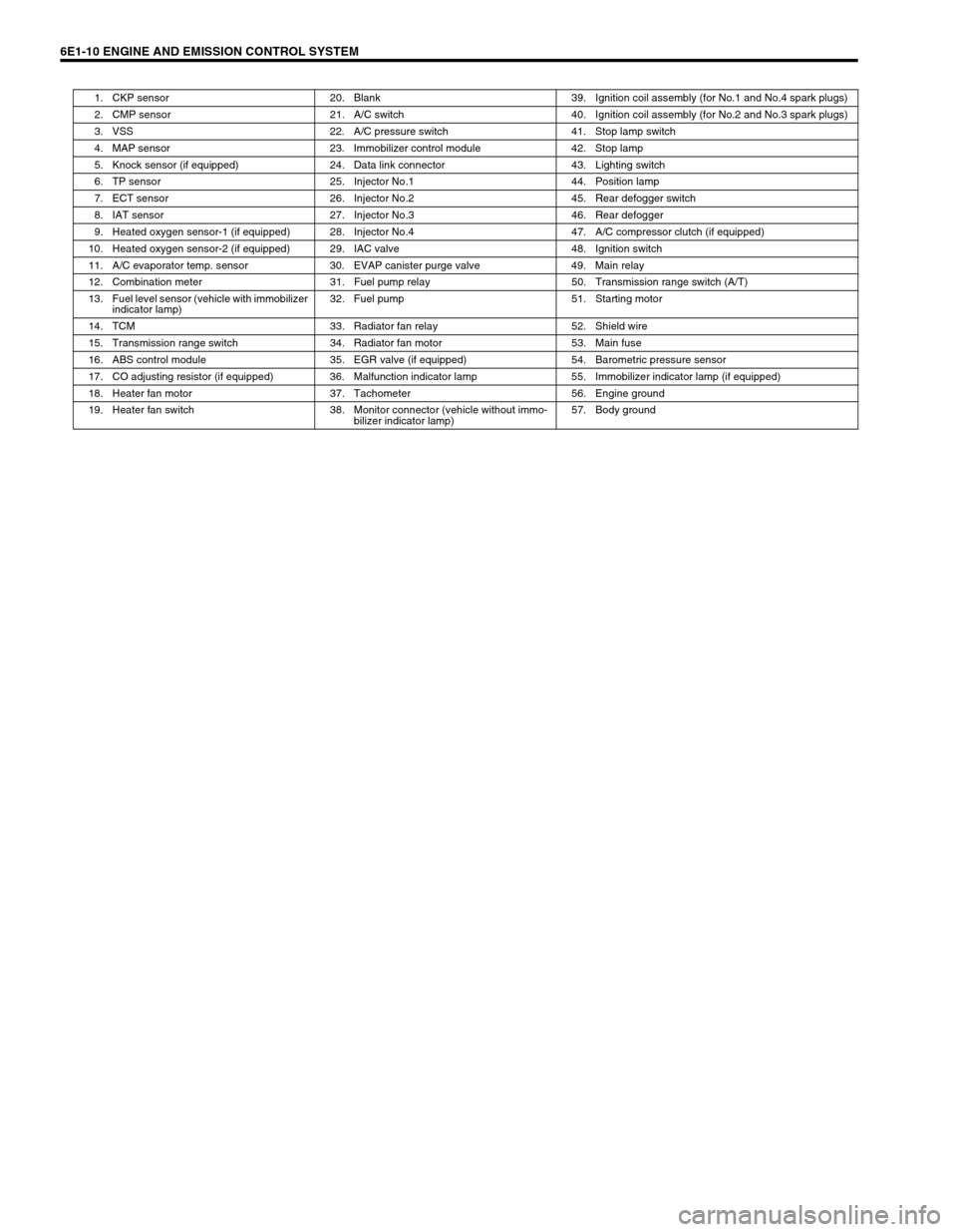
1. CKP sensor 20. Blank 39. Ignition coil assembly (for No.1 and No.4 spark plugs)
2. CMP sensor 21. A/C switch 40. Ignition coil assembly (for No.2 and No.3 spark plugs)
3. VSS 22. A/C pressure switch 41. Stop lamp switch
4. MAP sensor 23. Immobilizer control module 42. Stop lamp
5. Knock sensor (if equipped) 24. Data link connector 43. Lighting switch
6. TP sensor 25. Injector No.1 44. Position lamp
7. ECT sensor 26. Injector No.2 45. Rear defogger switch
8. IAT sensor 27. Injector No.3 46. Rear defogger
9. Heated oxygen sensor-1 (if equipped) 28. Injector No.4 47. A/C compressor clutch (if equipped)
10. Heated oxygen sensor-2 (if equipped) 29. IAC valve 48. Ignition switch
11. A/C evaporator temp. sensor 30. EVAP canister purge valve 49. Main relay
12. Combination meter 31. Fuel pump relay 50. Transmission range switch (A/T)
13. Fuel level sensor (vehicle with immobilizer
indicator lamp)32. Fuel pump 51. Starting motor
14. TCM 33. Radiator fan relay 52. Shield wire
15. Transmission range switch 34. Radiator fan motor 53. Main fuse
16. ABS control module 35. EGR valve (if equipped) 54. Barometric pressure sensor
17. CO adjusting resistor (if equipped) 36. Malfunction indicator lamp 55. Immobilizer indicator lamp (if equipped)
18. Heater fan motor 37. Tachometer 56. Engine ground
19. Heater fan switch 38. Monitor connector (vehicle without immo-
bilizer indicator lamp)57. Body ground
Page 633 of 698
6E1-12 ENGINE AND EMISSION CONTROL SYSTEM
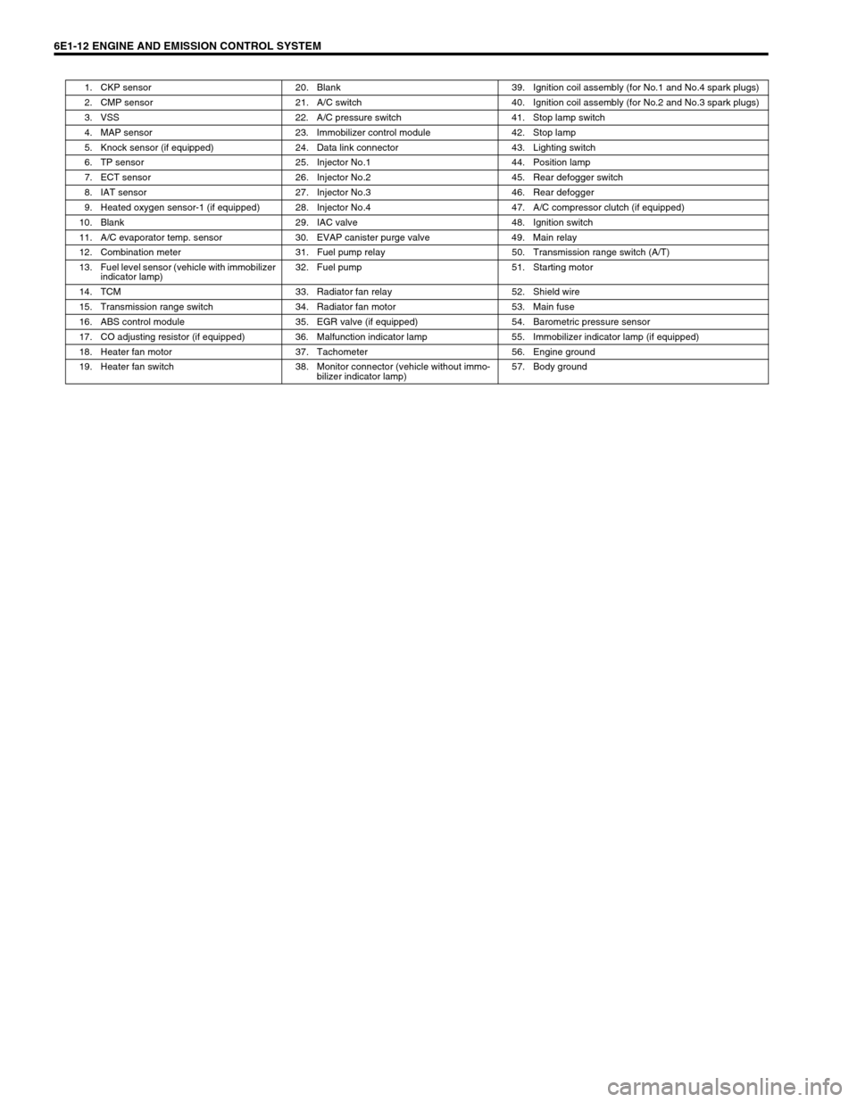
1. CKP sensor 20. Blank 39. Ignition coil assembly (for No.1 and No.4 spark plugs)
2. CMP sensor 21. A/C switch 40. Ignition coil assembly (for No.2 and No.3 spark plugs)
3. VSS 22. A/C pressure switch 41. Stop lamp switch
4. MAP sensor 23. Immobilizer control module 42. Stop lamp
5. Knock sensor (if equipped) 24. Data link connector 43. Lighting switch
6. TP sensor 25. Injector No.1 44. Position lamp
7. ECT sensor 26. Injector No.2 45. Rear defogger switch
8. IAT sensor 27. Injector No.3 46. Rear defogger
9. Heated oxygen sensor-1 (if equipped) 28. Injector No.4 47. A/C compressor clutch (if equipped)
10. Blank 29. IAC valve 48. Ignition switch
11. A/C evaporator temp. sensor 30. EVAP canister purge valve 49. Main relay
12. Combination meter 31. Fuel pump relay 50. Transmission range switch (A/T)
13. Fuel level sensor (vehicle with immobilizer
indicator lamp)32. Fuel pump 51. Starting motor
14. TCM 33. Radiator fan relay 52. Shield wire
15. Transmission range switch 34. Radiator fan motor 53. Main fuse
16. ABS control module 35. EGR valve (if equipped) 54. Barometric pressure sensor
17. CO adjusting resistor (if equipped) 36. Malfunction indicator lamp 55. Immobilizer indicator lamp (if equipped)
18. Heater fan motor 37. Tachometer 56. Engine ground
19. Heater fan switch 38. Monitor connector (vehicle without immo-
bilizer indicator lamp)57. Body ground