tow SUZUKI SWIFT 2000 1.G RG413 Service Workshop Manual
[x] Cancel search | Manufacturer: SUZUKI, Model Year: 2000, Model line: SWIFT, Model: SUZUKI SWIFT 2000 1.GPages: 698, PDF Size: 16.01 MB
Page 8 of 698
GENERAL INFORMATION 0A-5
Even when the accident was light enough not to cause air bags to activate, be sure to inspect sys-
tem parts and other related parts according to instructions under “REPAIR AND INSPECTION
REQUIRED AFTER AN ACCIDENT” in SECTION 10B.
When servicing parts other than air bag system, if shocks may be applied to air bag system compo-
nent parts, remove those parts beforehand.
When handling the air bag (inflator) modules (driver and passenger), seat belt pretensioners (driver
and passenger) or SDM, be careful not to drop it or apply an impact to it. If an excessive impact was
applied, never attempt disassembly or repair but replace it with a new one.
When grease, cleaning agent, oil, water, etc. has got onto air bag (inflator) modules (driver and pas-
senger) or seat belt pretensioners (drive and passenger), wipe off immediately with a dry cloth. WARNING:
SDM
For handling and storage of a SDM, select a place where the ambient temperature below 65°C
(150°F), without high humidity and away from electric noise.
During service procedures, be very careful when handling a Sensing and Diagnostic Module (SDM).
Never strike or jar the SDM.
Never power up the air bag system when the SDM is not rigidly attached to the vehicle. All SDM and
mounting bracket fasteners must be carefully torqued and the arrow must be pointing toward the
front of the vehicle to ensure proper operation of the air bag system.
The SDM could be activated when powered while not rigidly attached to the vehicle which could
cause deployment and result in personal injury.
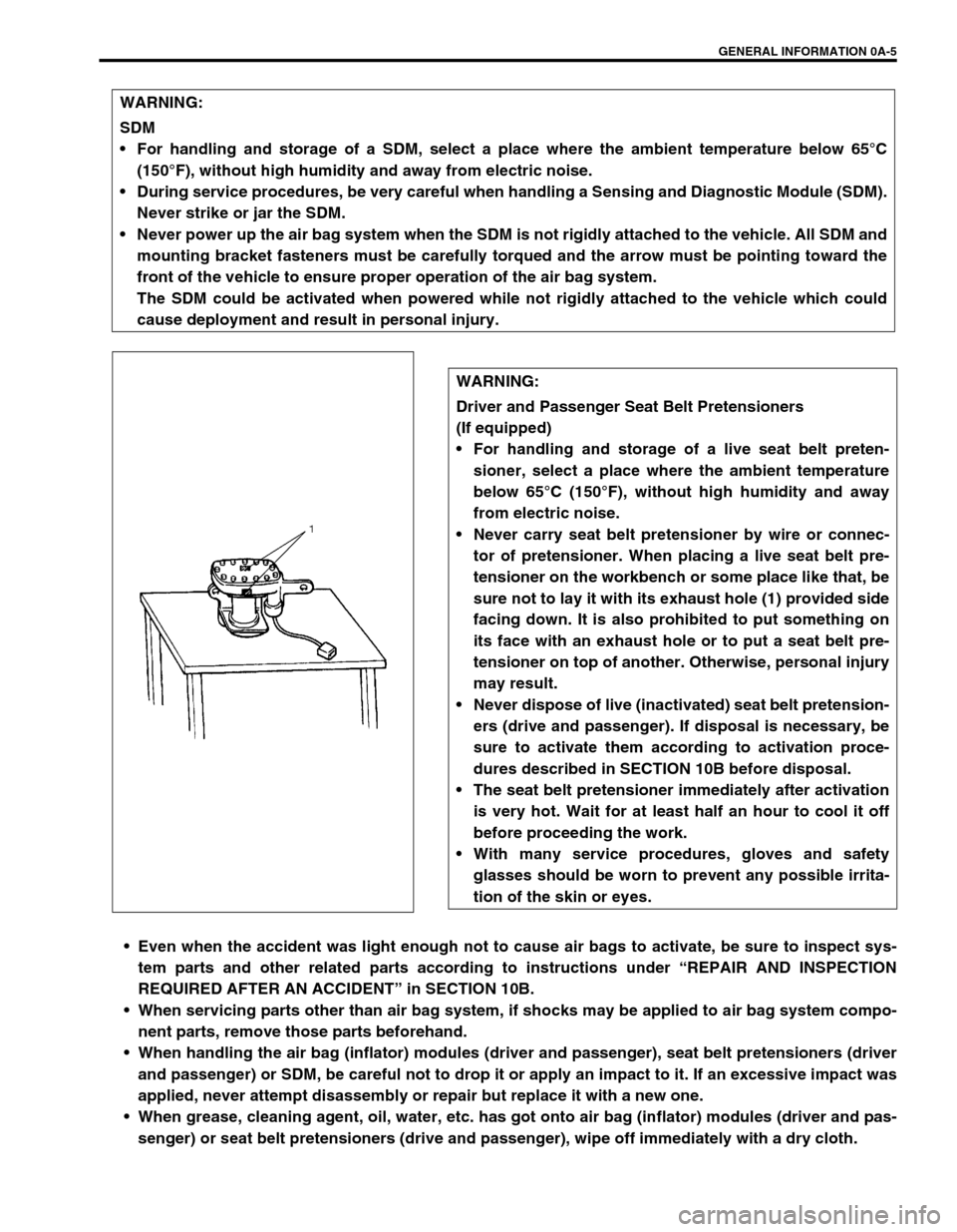
WARNING:
Driver and Passenger Seat Belt Pretensioners
(If equipped)
For handling and storage of a live seat belt preten-
sioner, select a place where the ambient temperature
below 65°C (150°F), without high humidity and away
from electric noise.
Never carry seat belt pretensioner by wire or connec-
tor of pretensioner. When placing a live seat belt pre-
tensioner on the workbench or some place like that, be
sure not to lay it with its exhaust hole (1) provided side
facing down. It is also prohibited to put something on
its face with an exhaust hole or to put a seat belt pre-
tensioner on top of another. Otherwise, personal injury
may result.
Never dispose of live (inactivated) seat belt pretension-
ers (drive and passenger). If disposal is necessary, be
sure to activate them according to activation proce-
dures described in SECTION 10B before disposal.
The seat belt pretensioner immediately after activation
is very hot. Wait for at least half an hour to cool it off
before proceeding the work.
With many service procedures, gloves and safety
glasses should be worn to prevent any possible irrita-
tion of the skin or eyes.
Page 13 of 698
0A-10 GENERAL INFORMATION
PRECAUTION IN SERVICING FULL-TIME 4WD
VEHICLE
This full-time 4WD vehicle can not be converted to 2WD man-
ually.
Observe the following caution in servicing. Otherwise, front
wheels drive rear wheels or vise-versa and vehicle acci-
dents, drivetrain damage and personal injury may result.
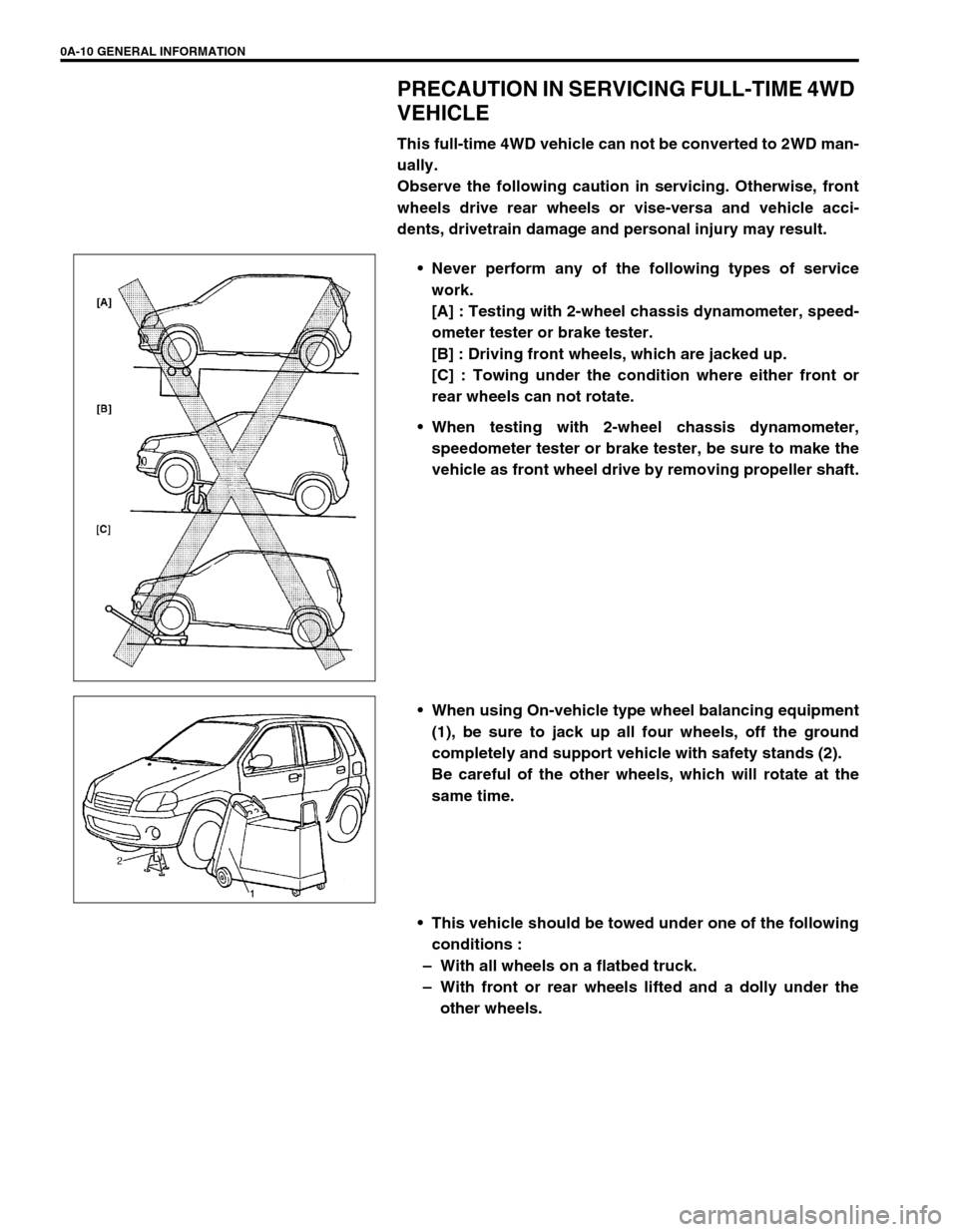
Never perform any of the following types of service
work.
[A] : Testing with 2-wheel chassis dynamometer, speed-
ometer tester or brake tester.
[B] : Driving front wheels, which are jacked up.
[C] : Towing under the condition where either front or
rear wheels can not rotate.
When testing with 2-wheel chassis dynamometer,
speedometer tester or brake tester, be sure to make the
vehicle as front wheel drive by removing propeller shaft.
When using On-vehicle type wheel balancing equipment
(1), be sure to jack up all four wheels, off the ground
completely and support vehicle with safety stands (2).
Be careful of the other wheels, which will rotate at the
same time.
This vehicle should be towed under one of the following
conditions :
– With all wheels on a flatbed truck.
– With front or rear wheels lifted and a dolly under the
other wheels.
Page 33 of 698
0B-4 MAINTENANCE AND LUBRICATION
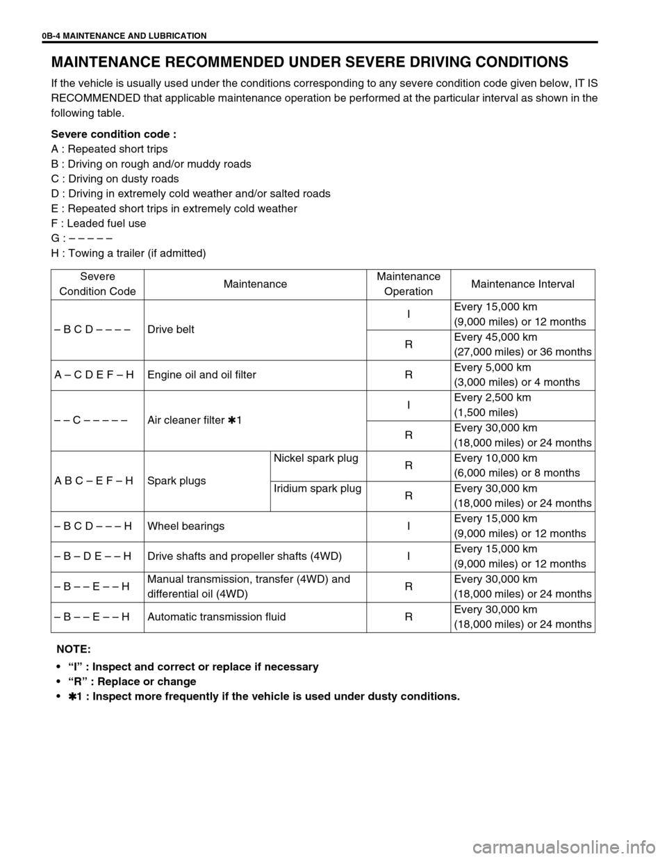
MAINTENANCE RECOMMENDED UNDER SEVERE DRIVING CONDITIONS
If the vehicle is usually used under the conditions corresponding to any severe condition code given below, IT IS
RECOMMENDED that applicable maintenance operation be performed at the particular interval as shown in the
following table.
Severe condition code :
A : Repeated short trips
B : Driving on rough and/or muddy roads
C : Driving on dusty roads
D : Driving in extremely cold weather and/or salted roads
E : Repeated short trips in extremely cold weather
F : Leaded fuel use
G : – – – – –
H : Towing a trailer (if admitted)
Severe
Condition CodeMaintenanceMaintenance
OperationMaintenance Interval
– B C D – – – –Drive beltIEvery 15,000 km
(9,000 miles) or 12 months
REvery 45,000 km
(27,000 miles) or 36 months
A – C D E F – H Engine oil and oil filter REvery 5,000 km
(3,000 miles) or 4 months
– – C – – – – –Air cleaner filter ✱1IEvery 2,500 km
(1,500 miles)
REvery 30,000 km
(18,000 miles) or 24 months
A B C – E F – H Spark plugsNickel spark plug
REvery 10,000 km
(6,000 miles) or 8 months
Iridium spark plug
REvery 30,000 km
(18,000 miles) or 24 months
– B C D – – – H Wheel bearings IEvery 15,000 km
(9,000 miles) or 12 months
– B – D E – – H Drive shafts and propeller shafts (4WD) IEvery 15,000 km
(9,000 miles) or 12 months
– B – – E – – HManual transmission, transfer (4WD) and
differential oil (4WD)REvery 30,000 km
(18,000 miles) or 24 months
– B – – E – – H Automatic transmission fluid REvery 30,000 km
(18,000 miles) or 24 months
NOTE:
“I” : Inspect and correct or replace if necessary
“R” : Replace or change
✱
✱✱ ✱1 : Inspect more frequently if the vehicle is used under dusty conditions.
Page 136 of 698
MANUAL RACK AND PINION 3B-15
INSTALLATION
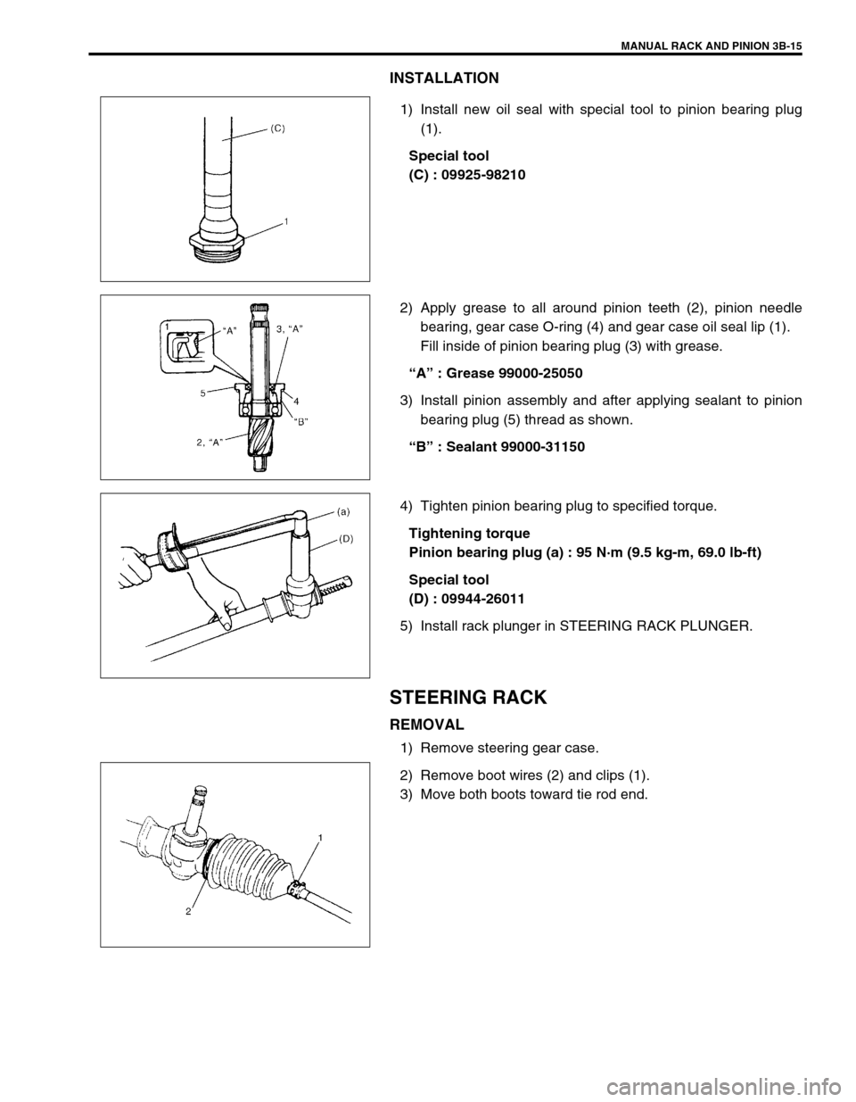
1) Install new oil seal with special tool to pinion bearing plug
(1).
Special tool
(C) : 09925-98210
2) Apply grease to all around pinion teeth (2), pinion needle
bearing, gear case O-ring (4) and gear case oil seal lip (1).
Fill inside of pinion bearing plug (3) with grease.
“A” : Grease 99000-25050
3) Install pinion assembly and after applying sealant to pinion
bearing plug (5) thread as shown.
“B” : Sealant 99000-31150
4) Tighten pinion bearing plug to specified torque.
Tightening torque
Pinion bearing plug (a) : 95 N·m (9.5 kg-m, 69.0 lb-ft)
Special tool
(D) : 09944-26011
5) Install rack plunger in STEERING RACK PLUNGER.
STEERING RACK
REMOVAL
1) Remove steering gear case.
2) Remove boot wires (2) and clips (1).
3) Move both boots toward tie rod end.
Page 237 of 698
3E-24 REAR SUSPENSION
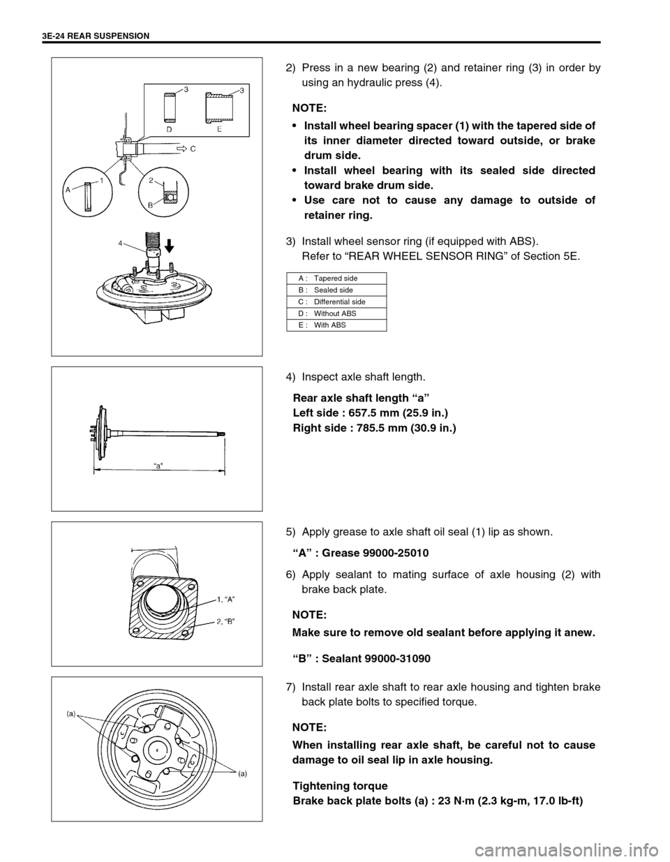
2) Press in a new bearing (2) and retainer ring (3) in order by
using an hydraulic press (4).
3) Install wheel sensor ring (if equipped with ABS).
Refer to “REAR WHEEL SENSOR RING” of Section 5E.
4) Inspect axle shaft length.
Rear axle shaft length “a”
Left side : 657.5 mm (25.9 in.)
Right side : 785.5 mm (30.9 in.)
5) Apply grease to axle shaft oil seal (1) lip as shown.
“A” : Grease 99000-25010
6) Apply sealant to mating surface of axle housing (2) with
brake back plate.
“B” : Sealant 99000-31090
7) Install rear axle shaft to rear axle housing and tighten brake
back plate bolts to specified torque.
Tightening torque
Brake back plate bolts (a) : 23 N·m (2.3 kg-m, 17.0 lb-ft) NOTE:
Install wheel bearing spacer (1) with the tapered side of
its inner diameter directed toward outside, or brake
drum side.
Install wheel bearing with its sealed side directed
toward brake drum side.
Use care not to cause any damage to outside of
retainer ring.
A : Tapered side
B : Sealed side
C : Differential side
D : Without ABS
E : With ABS
NOTE:
Make sure to remove old sealant before applying it anew.
NOTE:
When installing rear axle shaft, be careful not to cause
damage to oil seal lip in axle housing.
Page 259 of 698
4A-6 FRONT DRIVE SHAFT
3) Remove boot band, then pull out differential side boot from
shaft.
4) Pull out damper through shaft. (if equipped)
5) Undo boot bands of wheel side joint boot, then pull out boot
through shaft.
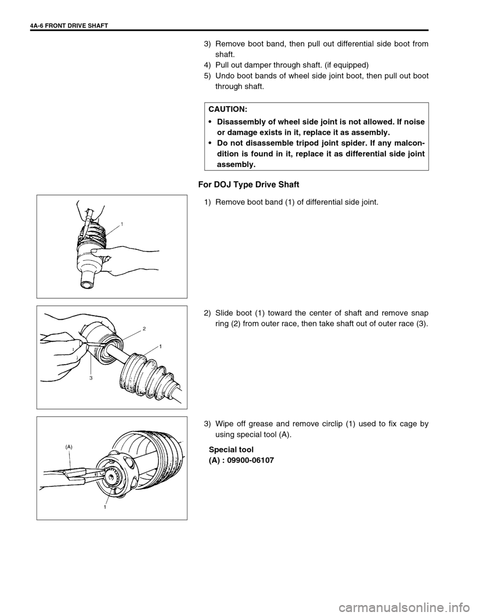
For DOJ Type Drive Shaft
1) Remove boot band (1) of differential side joint.
2) Slide boot (1) toward the center of shaft and remove snap
ring (2) from outer race, then take shaft out of outer race (3).
3) Wipe off grease and remove circlip (1) used to fix cage by
using special tool (A).
Special tool
(A) : 09900-06107 CAUTION:
Disassembly of wheel side joint is not allowed. If noise
or damage exists in it, replace it as assembly.
Do not disassemble tripod joint spider. If any malcon-
dition is found in it, replace it as differential side joint
assembly.
Page 281 of 698
5-8 BRAKES
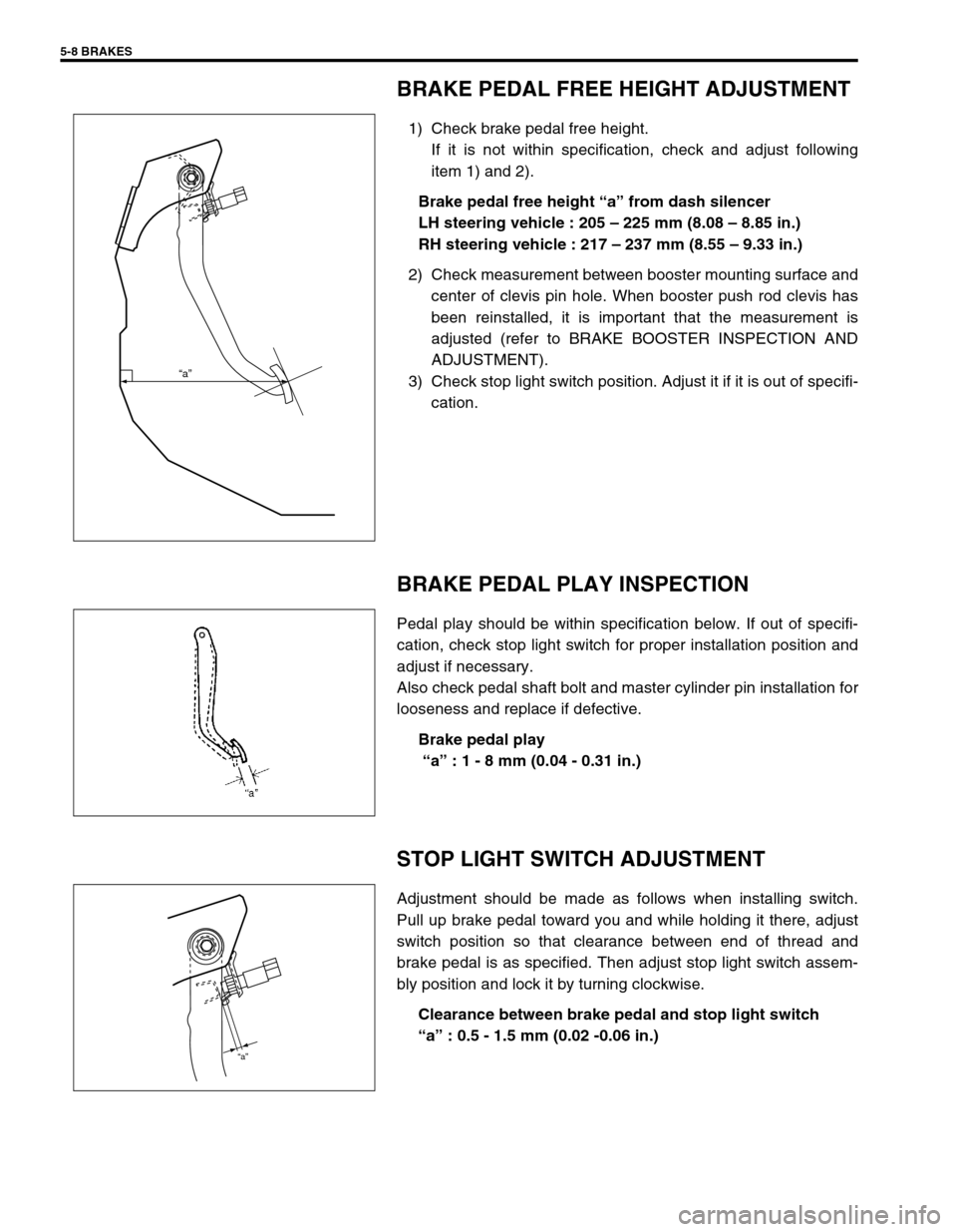
BRAKE PEDAL FREE HEIGHT ADJUSTMENT
1) Check brake pedal free height.
If it is not within specification, check and adjust following
item 1) and 2).
Brake pedal free height “a” from dash silencer
LH steering vehicle : 205 – 225 mm (8.08 – 8.85 in.)
RH steering vehicle : 217 – 237 mm (8.55 – 9.33 in.)
2) Check measurement between booster mounting surface and
center of clevis pin hole. When booster push rod clevis has
been reinstalled, it is important that the measurement is
adjusted (refer to BRAKE BOOSTER INSPECTION AND
ADJUSTMENT).
3) Check stop light switch position. Adjust it if it is out of specifi-
cation.
BRAKE PEDAL PLAY INSPECTION
Pedal play should be within specification below. If out of specifi-
cation, check stop light switch for proper installation position and
adjust if necessary.
Also check pedal shaft bolt and master cylinder pin installation for
looseness and replace if defective.
Brake pedal play
“a” : 1 - 8 mm (0.04 - 0.31 in.)
STOP LIGHT SWITCH ADJUSTMENT
Adjustment should be made as follows when installing switch.
Pull up brake pedal toward you and while holding it there, adjust
switch position so that clearance between end of thread and
brake pedal is as specified. Then adjust stop light switch assem-
bly position and lock it by turning clockwise.
Clearance between brake pedal and stop light switch
“a” : 0.5 - 1.5 mm (0.02 -0.06 in.)
“a”
“a”
Page 387 of 698
6-18 ENGINE GENERAL INFORMATION AND DIAGNOSIS
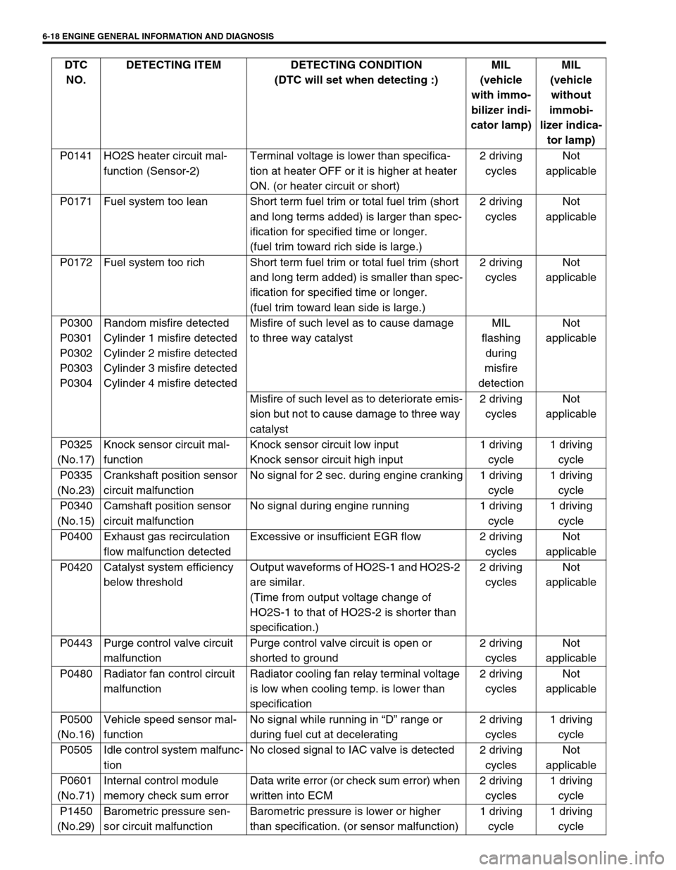
P0141 HO2S heater circuit mal-
function (Sensor-2)Terminal voltage is lower than specifica-
tion at heater OFF or it is higher at heater
ON. (or heater circuit or short)2 driving
cyclesNot
applicable
P0171 Fuel system too lean Short term fuel trim or total fuel trim (short
and long terms added) is larger than spec-
ification for specified time or longer.
(fuel trim toward rich side is large.)2 driving
cyclesNot
applicable
P0172 Fuel system too rich Short term fuel trim or total fuel trim (short
and long term added) is smaller than spec-
ification for specified time or longer.
(fuel trim toward lean side is large.)2 driving
cyclesNot
applicable
P0300
P0301
P0302
P0303
P0304Random misfire detected
Cylinder 1 misfire detected
Cylinder 2 misfire detected
Cylinder 3 misfire detected
Cylinder 4 misfire detectedMisfire of such level as to cause damage
to three way catalystMIL
flashing
during
misfire
detectionNot
applicable
Misfire of such level as to deteriorate emis-
sion but not to cause damage to three way
catalyst2 driving
cyclesNot
applicable
P0325
(No.17)Knock sensor circuit mal-
functionKnock sensor circuit low input
Knock sensor circuit high input1 driving
cycle1 driving
cycle
P0335
(No.23)Crankshaft position sensor
circuit malfunctionNo signal for 2 sec. during engine cranking 1 driving
cycle1 driving
cycle
P0340
(No.15)Camshaft position sensor
circuit malfunctionNo signal during engine running 1 driving
cycle1 driving
cycle
P0400 Exhaust gas recirculation
flow malfunction detectedExcessive or insufficient EGR flow 2 driving
cyclesNot
applicable
P0420 Catalyst system efficiency
below thresholdOutput waveforms of HO2S-1 and HO2S-2
are similar.
(Time from output voltage change of
HO2S-1 to that of HO2S-2 is shorter than
specification.)2 driving
cyclesNot
applicable
P0443 Purge control valve circuit
malfunctionPurge control valve circuit is open or
shorted to ground2 driving
cyclesNot
applicable
P0480 Radiator fan control circuit
malfunctionRadiator cooling fan relay terminal voltage
is low when cooling temp. is lower than
specification2 driving
cyclesNot
applicable
P0500
(No.16)Vehicle speed sensor mal-
functionNo signal while running in “D” range or
during fuel cut at decelerating2 driving
cycles1 driving
cycle
P0505 Idle control system malfunc-
tionNo closed signal to IAC valve is detected 2 driving
cyclesNot
applicable
P0601
(No.71)Internal control module
memory check sum errorData write error (or check sum error) when
written into ECM2 driving
cycles1 driving
cycle
P1450
(No.29)Barometric pressure sen-
sor circuit malfunctionBarometric pressure is lower or higher
than specification. (or sensor malfunction)1 driving
cycle1 driving
cycle DTC
NO.DETECTING ITEM DETECTING CONDITION
(DTC will set when detecting :)MIL
(vehicle
with immo-
bilizer indi-
cator lamp)MIL
(vehicle
without
immobi-
lizer indica-
tor lamp)
Page 543 of 698
6A1-42 ENGINE MECHANICAL (M13 ENGINE)
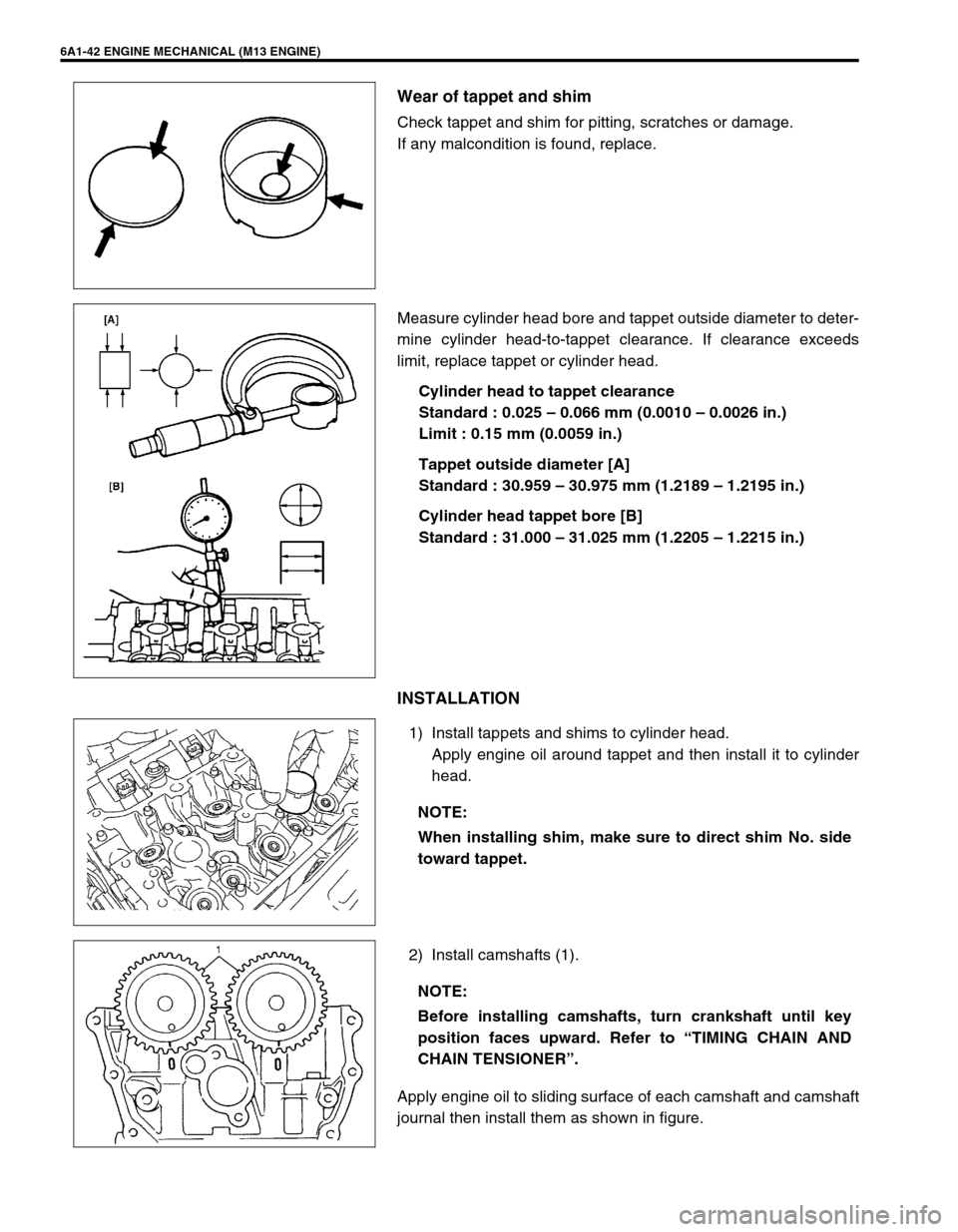
Wear of tappet and shim
Check tappet and shim for pitting, scratches or damage.
If any malcondition is found, replace.
Measure cylinder head bore and tappet outside diameter to deter-
mine cylinder head-to-tappet clearance. If clearance exceeds
limit, replace tappet or cylinder head.
Cylinder head to tappet clearance
Standard : 0.025 – 0.066 mm (0.0010 – 0.0026 in.)
Limit : 0.15 mm (0.0059 in.)
Tappet outside diameter [A]
Standard : 30.959 – 30.975 mm (1.2189 – 1.2195 in.)
Cylinder head tappet bore [B]
Standard : 31.000 – 31.025 mm (1.2205 – 1.2215 in.)
INSTALLATION
1) Install tappets and shims to cylinder head.
Apply engine oil around tappet and then install it to cylinder
head.
2) Install camshafts (1).
Apply engine oil to sliding surface of each camshaft and camshaft
journal then install them as shown in figure.
NOTE:
When installing shim, make sure to direct shim No. side
toward tappet.
NOTE:
Before installing camshafts, turn crankshaft until key
position faces upward. Refer to “TIMING CHAIN AND
CHAIN TENSIONER”.
Page 556 of 698
ENGINE MECHANICAL (M13 ENGINE) 6A1-55
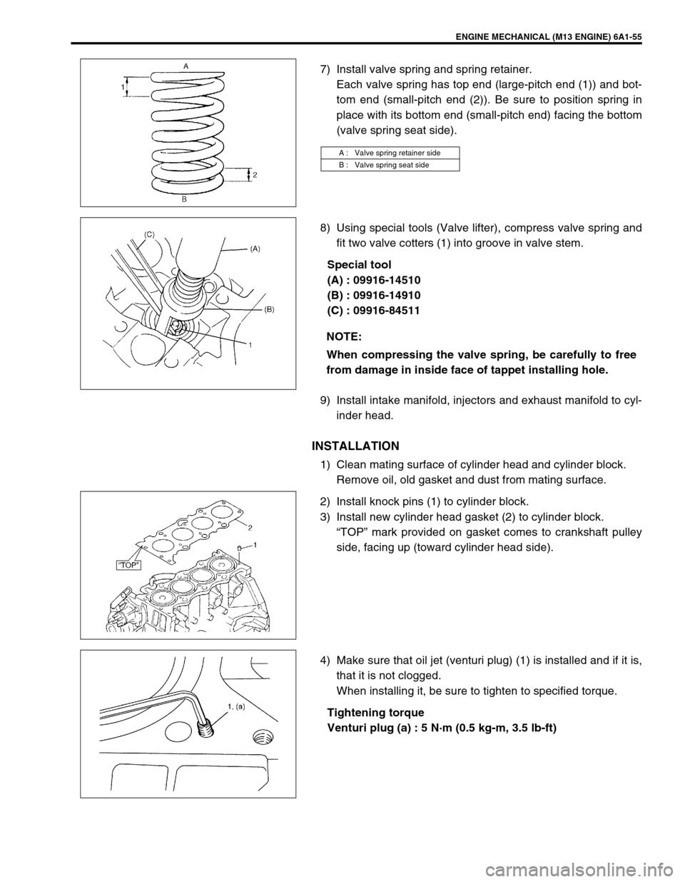
7) Install valve spring and spring retainer.
Each valve spring has top end (large-pitch end (1)) and bot-
tom end (small-pitch end (2)). Be sure to position spring in
place with its bottom end (small-pitch end) facing the bottom
(valve spring seat side).
8) Using special tools (Valve lifter), compress valve spring and
fit two valve cotters (1) into groove in valve stem.
Special tool
(A) : 09916-14510
(B) : 09916-14910
(C) : 09916-84511
9) Install intake manifold, injectors and exhaust manifold to cyl-
inder head.
INSTALLATION
1) Clean mating surface of cylinder head and cylinder block.
Remove oil, old gasket and dust from mating surface.
2) Install knock pins (1) to cylinder block.
3) Install new cylinder head gasket (2) to cylinder block.
“TOP” mark provided on gasket comes to crankshaft pulley
side, facing up (toward cylinder head side).
4) Make sure that oil jet (venturi plug) (1) is installed and if it is,
that it is not clogged.
When installing it, be sure to tighten to specified torque.
Tightening torque
Venturi plug (a) : 5 N·m (0.5 kg-m, 3.5 lb-ft)
A : Valve spring retainer side
B : Valve spring seat side
NOTE:
When compressing the valve spring, be carefully to free
from damage in inside face of tappet installing hole.