Ignition coil SUZUKI SWIFT 2000 1.G RG413 Service User Guide
[x] Cancel search | Manufacturer: SUZUKI, Model Year: 2000, Model line: SWIFT, Model: SUZUKI SWIFT 2000 1.GPages: 698, PDF Size: 16.01 MB
Page 399 of 698
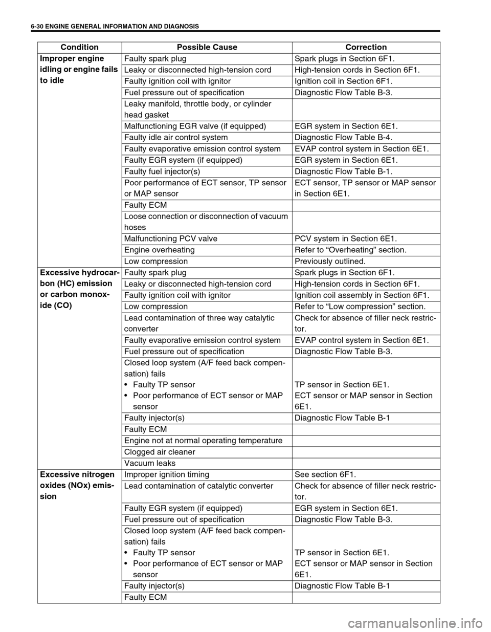
6-30 ENGINE GENERAL INFORMATION AND DIAGNOSIS
Improper engine
idling or engine fails
to idleFaulty spark plug Spark plugs in Section 6F1.
Leaky or disconnected high-tension cord High-tension cords in Section 6F1.
Faulty ignition coil with ignitor Ignition coil in Section 6F1.
Fuel pressure out of specification Diagnostic Flow Table B-3.
Leaky manifold, throttle body, or cylinder
head gasket
Malfunctioning EGR valve (if equipped) EGR system in Section 6E1.
Faulty idle air control system Diagnostic Flow Table B-4.
Faulty evaporative emission control system EVAP control system in Section 6E1.
Faulty EGR system (if equipped) EGR system in Section 6E1.
Faulty fuel injector(s) Diagnostic Flow Table B-1.
Poor performance of ECT sensor, TP sensor
or MAP sensorECT sensor, TP sensor or MAP sensor
in Section 6E1.
Faulty ECM
Loose connection or disconnection of vacuum
hoses
Malfunctioning PCV valve PCV system in Section 6E1.
Engine overheating Refer to “Overheating” section.
Low compression Previously outlined.
Excessive hydrocar-
bon (HC) emission
or carbon monox-
ide (CO)Faulty spark plug Spark plugs in Section 6F1.
Leaky or disconnected high-tension cord High-tension cords in Section 6F1.
Faulty ignition coil with ignitor Ignition coil assembly in Section 6F1.
Low compression Refer to “Low compression” section.
Lead contamination of three way catalytic
converterCheck for absence of filler neck restric-
tor.
Faulty evaporative emission control system EVAP control system in Section 6E1.
Fuel pressure out of specification Diagnostic Flow Table B-3.
Closed loop system (A/F feed back compen-
sation) fails
Faulty TP sensor
Poor performance of ECT sensor or MAP
sensorTP sensor in Section 6E1.
ECT sensor or MAP sensor in Section
6E1.
Faulty injector(s) Diagnostic Flow Table B-1
Faulty ECM
Engine not at normal operating temperature
Clogged air cleaner
Vacuum leaks
Excessive nitrogen
oxides (NOx) emis-
sionImproper ignition timing See section 6F1.
Lead contamination of catalytic converter Check for absence of filler neck restric-
tor.
Faulty EGR system (if equipped) EGR system in Section 6E1.
Fuel pressure out of specification Diagnostic Flow Table B-3.
Closed loop system (A/F feed back compen-
sation) fails
Faulty TP sensor
Poor performance of ECT sensor or MAP
sensorTP sensor in Section 6E1.
ECT sensor or MAP sensor in Section
6E1.
Faulty injector(s) Diagnostic Flow Table B-1
Faulty ECM Condition Possible Cause Correction
Page 406 of 698
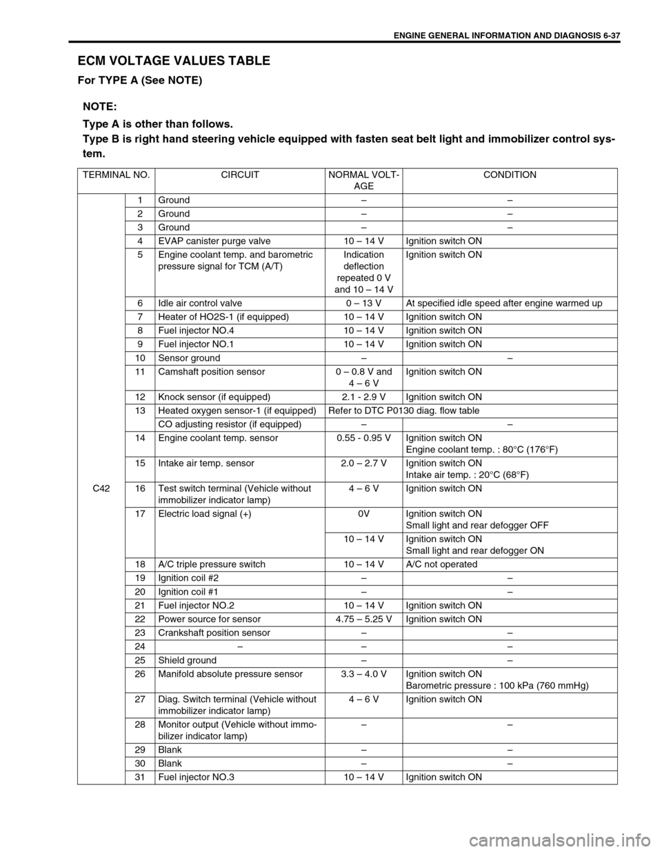
ENGINE GENERAL INFORMATION AND DIAGNOSIS 6-37
ECM VOLTAGE VALUES TABLE
For TYPE A (See NOTE)
NOTE:
Type A is other than follows.
Type B is right hand steering vehicle equipped with fasten seat belt light and immobilizer control sys-
tem.
TERMINAL NO. CIRCUIT NORMAL VOLT-
AGECONDITION
C421 Ground––
2 Ground––
3 Ground––
4 EVAP canister purge valve 10 – 14 V Ignition switch ON
5 Engine coolant temp. and barometric
pressure signal for TCM (A/T)Indication
deflection
repeated 0 V
and 10 – 14 VIgnition switch ON
6 Idle air control valve 0 – 13 V At specified idle speed after engine warmed up
7 Heater of HO2S-1 (if equipped) 10 – 14 V Ignition switch ON
8 Fuel injector NO.4 10 – 14 V Ignition switch ON
9 Fuel injector NO.1 10 – 14 V Ignition switch ON
10 Sensor ground––
11 Camshaft position sensor 0 – 0.8 V and
4 – 6 VIgnition switch ON
12 Knock sensor (if equipped) 2.1 - 2.9 V Ignition switch ON
13 Heated oxygen sensor-1 (if equipped) Refer to DTC P0130 diag. flow table
CO adjusting resistor (if equipped)––
14 Engine coolant temp. sensor 0.55 - 0.95 V Ignition switch ON
Engine coolant temp. : 80°C (176°F)
15 Intake air temp. sensor 2.0 – 2.7 V Ignition switch ON
Intake air temp. : 20°C (68°F)
16 Test switch terminal (Vehicle without
immobilizer indicator lamp)4 – 6 V Ignition switch ON
17 Electric load signal (+) 0V Ignition switch ON
Small light and rear defogger OFF
10 – 14 V Ignition switch ON
Small light and rear defogger ON
18 A/C triple pressure switch 10 – 14 V A/C not operated
19 Ignition coil #2––
20 Ignition coil #1––
21 Fuel injector NO.2 10 – 14 V Ignition switch ON
22 Power source for sensor 4.75 – 5.25 V Ignition switch ON
23 Crankshaft position sensor––
24–– –
25 Shield ground––
26 Manifold absolute pressure sensor 3.3 – 4.0 V Ignition switch ON
Barometric pressure : 100 kPa (760 mmHg)
27 Diag. Switch terminal (Vehicle without
immobilizer indicator lamp)4 – 6 V Ignition switch ON
28 Monitor output (Vehicle without immo-
bilizer indicator lamp)––
29 Blank––
30 Blank––
31 Fuel injector NO.3 10 – 14 V Ignition switch ON
Page 407 of 698
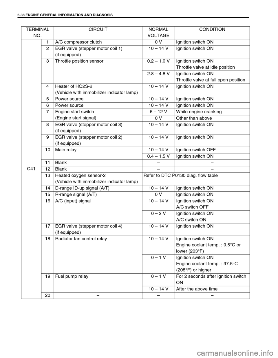
6-38 ENGINE GENERAL INFORMATION AND DIAGNOSIS
TERMINAL
NO.CIRCUIT NORMAL
VOLTAGECONDITION
C411 A/C compressor clutch 0 V Ignition switch ON
2 EGR valve (stepper motor coil 1)
(if equipped)10 – 14 V Ignition switch ON
3 Throttle position sensor 0.2 – 1.0 V Ignition switch ON
Throttle valve at idle position
2.8 – 4.8 V Ignition switch ON
Throttle valve at full open position
4 Heater of HO2S-2
(Vehicle with immobilizer indicator lamp)10 – 14 V Ignition switch ON
5 Power source 10 – 14 V Ignition switch ON
6 Power source 10 – 14 V Ignition switch ON
7 Engine start switch
(Engine start signal)6 – 12 V While engine cranking
0 V Other than above
8 EGR valve (stepper motor coil 3)
(if equipped)10 – 14 V Ignition switch ON
9 EGR valve (stepper motor coil 2)
(if equipped)10 – 14 V Ignition switch ON
10 Main relay 10 – 14 V Ignition switch OFF
0.4 – 1.5 V Ignition switch ON
11 Blank––
12 Blank––
13 Heated oxygen sensor-2
(Vehicle with immobilizer indicator lamp)Refer to DTC P0130 diag. flow table
14 D-range ID-up signal (A/T) 10 – 14 V Ignition switch ON
15 R-range signal (A/T) 0 V Ignition switch ON
16 A/C (input) signal 10 – 14 V Ignition switch ON
A/C switch OFF
0 – 2 V Ignition switch ON
A/C switch ON
17 EGR valve (stepper motor coil 4)
(if equipped)10 – 14 V Ignition switch ON
18 Radiator fan control relay 10 – 14 V Ignition switch ON
Engine coolant temp. : 9.5°C or
lower (203°F)
0 – 1 V Ignition switch ON
Engine coolant temp. : 97.5°C
(208°F) or higher
19 Fuel pump relay 0 – 1 V For 2 seconds after ignition switch
ON
10 – 14 V After the above time
20–––
Page 409 of 698
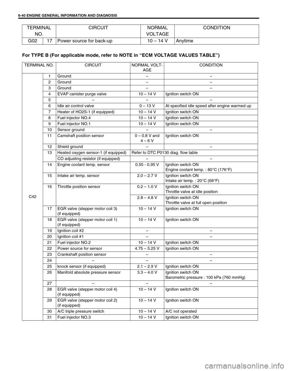
6-40 ENGINE GENERAL INFORMATION AND DIAGNOSIS
For TYPE B (For applicable mode, refer to NOTE in “ECM VOLTAGE VALUES TABLE”) G02 17 Power source for back-up 10 – 14 V Anytime
TERMINAL NO. CIRCUIT NORMAL VOLT-
AGECONDITION
C421Ground––
2Ground––
3Ground––
4 EVAP canister purge valve 10 – 14 V Ignition switch ON
5–– –
6 Idle air control valve 0 – 13 V At specified idle speed after engine warmed up
7 Heater of HO2S-1 (if equipped) 10 – 14 V Ignition switch ON
8 Fuel injector NO.4 10 – 14 V Ignition switch ON
9 Fuel injector NO.1 10 – 14 V Ignition switch ON
10 Sensor ground––
11 Camshaft position sensor 0 – 0.8 V and
4 – 6 VIgnition switch ON
12 Shield ground––
13 Heated oxygen sensor-1 (if equipped) Refer to DTC P0130 diag. flow table
CO adjusting resistor (if equipped)––
14 Engine coolant temp. sensor 0.55 - 0.95 V Ignition switch ON
Engine coolant temp. : 80°C (176°F)
15 Intake air temp. sensor 2.0 – 2.7 V Ignition switch ON
Intake air temp. : 20°C (68°F)
16 Throttle position sensor 0.2 – 1.0 V Ignition switch ON
Throttle valve at idle position
2.8 – 4.8 V Ignition switch ON
Throttle valve at full open position
17 EGR valve (stepper motor coil 3)
(if equipped)10 – 14 V Ignition switch ON
18 EGR valve (stepper motor coil 1)
(if equipped)10 – 14 V Ignition switch ON
19 Ignition coil #2––
20 Ignition coil #1––
21 Fuel injector NO.2 10 – 14 V Ignition switch ON
22 Power source for sensor 4.75 – 5.25 V Ignition switch ON
23 Crankshaft position sensor––
24–– –
25 knock sensor (if equipped) 2.1 – 2.9 V Ignition switch ON
26 Manifold absolute pressure sensor 3.3 – 4.0 V Ignition switch ON
Barometric pressure : 100 kPa (760 mmHg)
27–– –
28 EGR valve (stepper motor coil 4)
(if equipped)10 – 14 V Ignition switch ON
29 EGR valve (stepper motor coil 2)
(if equipped)10 – 14 V Ignition switch ON
30 A/C triple pressure switch 10 – 14 V A/C not operated
31 Fuel injector NO.3 10 – 14 V Ignition switch ON
TERMINAL
NO.CIRCUIT NORMAL
VOLTAGECONDITION
Page 412 of 698
ENGINE GENERAL INFORMATION AND DIAGNOSIS 6-43
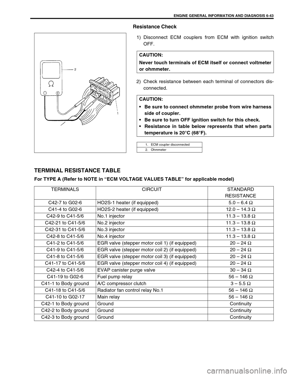
Resistance Check
1) Disconnect ECM couplers from ECM with ignition switch
OFF.
2) Check resistance between each terminal of connectors dis-
connected.
TERMINAL RESISTANCE TABLE
For TYPE A (Refer to NOTE in “ECM VOLTAGE VALUES TABLE” for applicable model) CAUTION:
Never touch terminals of ECM itself or connect voltmeter
or ohmmeter.
CAUTION:
Be sure to connect ohmmeter probe from wire harness
side of coupler.
Be sure to turn OFF ignition switch for this check.
Resistance in table below represents that when parts
temperature is 20°C (68°F).
1. ECM coupler disconnected
2. Ohmmeter
TERMINALS CIRCUIT STANDARD
RESISTANCE
C42-7 to G02-6 HO2S-1 heater (if equipped) 5.0 – 6.4 Ω
C41-4 to G02-6 HO2S-2 heater (if equipped) 12.0 – 14.3 Ω
C42-9 to C41-5/6 No.1 injector 11.3 – 13.8 Ω
C42-21 to C41-5/6 No.2 injector 11.3 – 13.8 Ω
C42-31 to C41-5/6 No.3 injector 11.3 – 13.8 Ω
C42-8 to C41-5/6 No.4 injector 11.3 – 13.8 Ω
C41-2 to C41-5/6 EGR valve (stepper motor coil 1) (if equipped) 20 – 24 Ω
C41-9 to C41-5/6 EGR valve (stepper motor coil 2) (if equipped) 20 – 24 Ω
C41-8 to C41-5/6 EGR valve (stepper motor coil 3) (if equipped) 20 – 24 Ω
C41-17 to C41-5/6 EGR valve (stepper motor coil 4) (if equipped) 20 – 24 Ω
C42-4 to C41-5/6 EVAP canister purge valve 30 – 34 Ω
C41-19 to G02-6 Fuel pump relay 56 – 146 Ω
C41-1 to Body ground A/C compressor clutch 3 – 5.5 Ω
C41-18 to C41-5/6 Radiator fan control relay No.1 56 – 146 Ω
C41-10 to G02-17 Main relay 56 – 146 Ω
C42-1 to Body ground Ground Continuity
C42-2 to Body ground Ground Continuity
C42-3 to Body ground Ground Continuity
Page 414 of 698
ENGINE GENERAL INFORMATION AND DIAGNOSIS 6-45
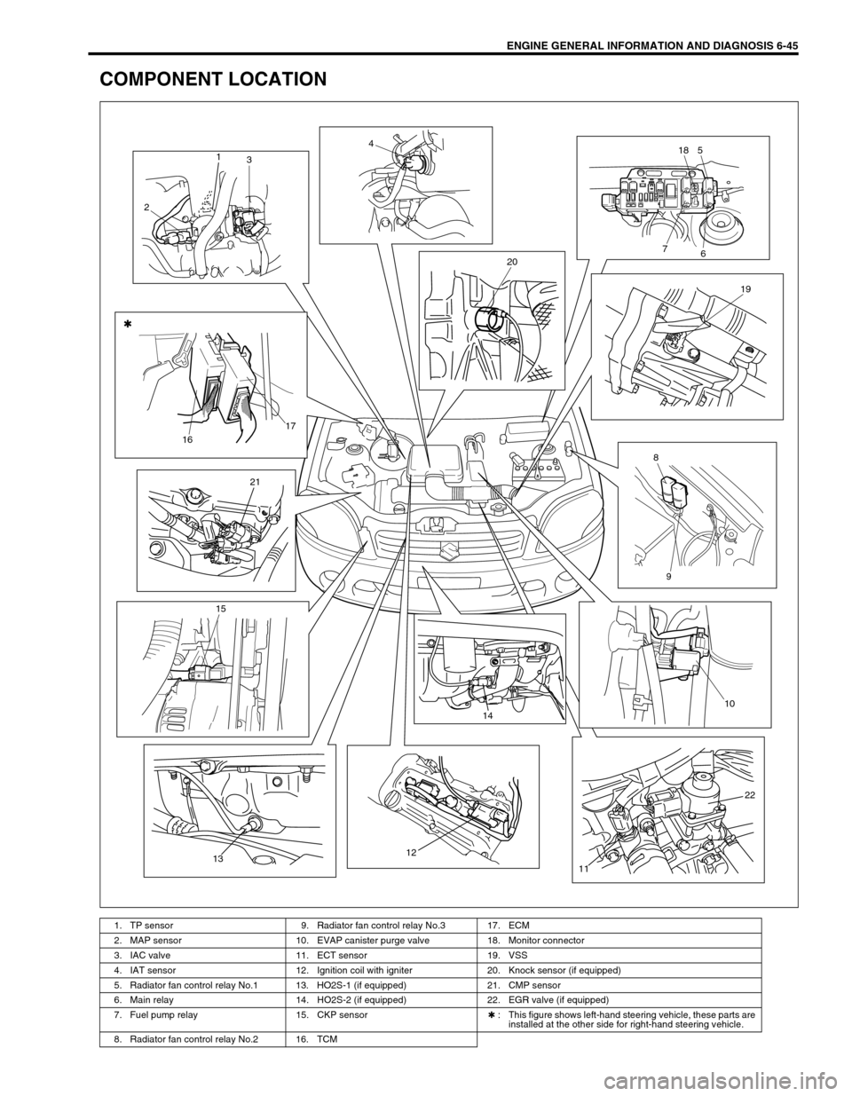
COMPONENT LOCATION
1. TP sensor 9. Radiator fan control relay No.3 17. ECM
2. MAP sensor 10. EVAP canister purge valve 18. Monitor connector
3. IAC valve 11. ECT sensor 19. VSS
4. IAT sensor 12. Ignition coil with igniter 20. Knock sensor (if equipped)
5. Radiator fan control relay No.1 13. HO2S-1 (if equipped) 21. CMP sensor
6. Main relay 14. HO2S-2 (if equipped) 22. EGR valve (if equipped)
7. Fuel pump relay 15. CKP sensor✱ : This figure shows left-hand steering vehicle, these parts are
installed at the other side for right-hand steering vehicle.
8. Radiator fan control relay No.2 16. TCM
1
3
24
518
6 7
20
19
8
9 1617
21
15
131214
10
22
11
Page 450 of 698
ENGINE GENERAL INFORMATION AND DIAGNOSIS 6-81
DTC P0300 RANDOM MISFIRE DETECTED (MISFIRE DETECTED AT 2 OR
MORE CYLINDERS)
DTC P0301 CYLINDER 1 MISFIRE DETECTED
DTC P0302 CYLINDER 2 MISFIRE DETECTED
DTC P0303 CYLINDER 3 MISFIRE DETECTED
DTC P0304 CYLINDER 4 MISFIRE DETECTED
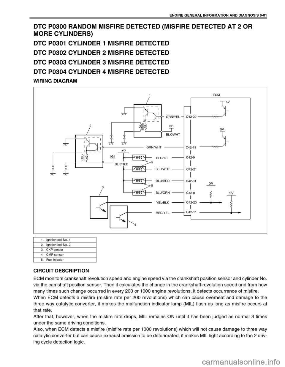
WIRING DIAGRAM
CIRCUIT DESCRIPTION
ECM monitors crankshaft revolution speed and engine speed via the crankshaft position sensor and cylinder No.
via the camshaft position sensor. Then it calculates the change in the crankshaft revolution speed and from how
many times such change occurred in every 200 or 1000 engine revolutions, it detects occurrence of misfire.
When ECM detects a misfire (misfire rate per 200 revolutions) which can cause overheat and damage to the
three way catalytic converter, it makes the malfunction indicator lamp (MIL) flash as long as misfire occurs at
that rate.
After that, however, when the misfire rate drops, MIL remains ON until it has been judged as normal 3 times
under the same driving conditions.
Also, when ECM detects a misfire (misfire rate per 1000 revolutions) which will not cause damage to three way
catalytic converter but can cause exhaust emission to be deteriorated, it makes MIL light according to the 2 driv-
ing cycle detection logic.
1. Ignition coil No. 1
2. Ignition coil No. 2
3. CKP sensor
4. CMP sensor
5. Fuel injector
C42-20
C42-19
ECM
IG1
5V
5V
GRN/YEL
BLK/WHT
GRN/WHT
IG1 2
+B
C42-9
C42-21
C42-8
C42-23 C42-31 BLU/YEL
BLU/WHT
BLU/RED
BLU/ORN
YEL/BLK
5V
C42-11
RED/YEL
5V
BLK/RED
3
45
5
1
Page 451 of 698
6-82 ENGINE GENERAL INFORMATION AND DIAGNOSIS
DTC CONFIRMATION PROCEDURE
1) Turn ignition switch OFF.
2) Clear DTC with ignition switch ON.
3) Check vehicle and environmental condition for :
–Altitude (barometric pressure) : 2400 m, 8000 ft or less (560 mmHg, 75 kPa or more)
–Ambient temp. : –10°C, 14°F or higher
–Intake air temp. : 70°C, 158°F or lower
–Engine coolant temp. : – 10 – 110°C, 14 – 230°F
4) Start engine and keep it at idle for 2 min. or more.
5) Check DTC in “DTC” mode and pending DTC in “ON BOARD TEST” or “PENDING DTC” mode.
6) If DTC is not detected at idle, consult usual driving based on information obtained in “Customer complaint
analysis” and “Freeze frame data check”.
INSPECTION
DTC DETECTING CONDITION POSSIBLE CAUSE
Engine under other than high revolution condition
Not on rough road
Engine speed changing rate (Below specified value)
Manifold absolute pressure changing rate (Below
specified value)
Throttle opening changing rate (Below specified
value)
Misfire rate per 200 or 1000 engine revolutions (how
much and how often crankshaft revolution speed
changes) is higher than specified valueEngine overheating
Vacuum leaks (air inhaling) from air intake system
Ignition system malfunction (spark plug(s), high-
tension cord(s), ignition coil assembly)
Fuel pressure out of specification
Fuel injector malfunction (clogged or leakage)
Engine compression out of specification
Valve lash (clearance) out of specification
Manifold absolute pressure sensor malfunction
Engine coolant temp. sensor malfunction
PCV valve malfunction
EVAP control system malfunction
EGR system malfunction
NOTE:
Among different types of random misfire, if misfire occurs at cylinders 1 and 4 or cylinders 3 and 2
simultaneously, it may not possible to reconfirm DTC by using the following DTC confirmation proce-
dure. When diagnosing the trouble of DTC P0300 (Random misfire detected) of the engine which is
apparently misfiring, even if DTC P0300 cannot be reconfirmed by using the following DTC confirma-
tion procedure, proceed to the following Diag. Flow Table.
WARNING:
When performing a road test, select a place where there is no traffic or possibility of a traffic acci-
dent and be very careful during testing to avoid occurrence of an accident.
Road test should be carried out with 2 persons, a driver and a tester.
CAUTION:
For iridium spark plugs, do not adjust air gap or clean.
Step Action Yes No
1Was “ENGINE DIAG. FLOW TABLE” performed? Go to Step 2. Go to “ENGINE
DIAG. FLOW
TABLE”.
Page 465 of 698
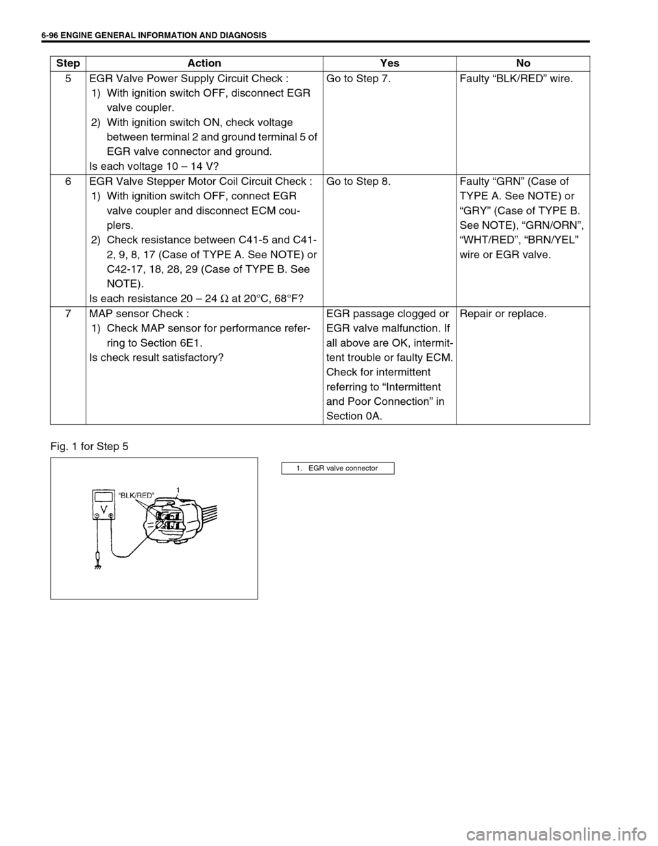
6-96 ENGINE GENERAL INFORMATION AND DIAGNOSIS
Fig. 1 for Step 55 EGR Valve Power Supply Circuit Check :
1) With ignition switch OFF, disconnect EGR
valve coupler.
2) With ignition switch ON, check voltage
between terminal 2 and ground terminal 5 of
EGR valve connector and ground.
Is each voltage 10 – 14 V?Go to Step 7. Faulty “BLK/RED” wire.
6 EGR Valve Stepper Motor Coil Circuit Check :
1) With ignition switch OFF, connect EGR
valve coupler and disconnect ECM cou-
plers.
2) Check resistance between C41-5 and C41-
2, 9, 8, 17 (Case of TYPE A. See NOTE) or
C42-17, 18, 28, 29 (Case of TYPE B. See
NOTE).
Is each resistance 20 – 24 Ω at 20°C, 68°F?Go to Step 8. Faulty “GRN” (Case of
TYPE A. See NOTE) or
“GRY” (Case of TYPE B.
See NOTE), “GRN/ORN”,
“WHT/RED”, “BRN/YEL”
wire or EGR valve.
7 MAP sensor Check :
1) Check MAP sensor for performance refer-
ring to Section 6E1.
Is check result satisfactory?EGR passage clogged or
EGR valve malfunction. If
all above are OK, intermit-
tent trouble or faulty ECM.
Check for intermittent
referring to “Intermittent
and Poor Connection” in
Section 0A.Repair or replace. Step Action Yes No
1. EGR valve connector
Page 505 of 698

6A1-4 ENGINE MECHANICAL (M13 ENGINE)
DIAGNOSIS
DIAGNOSIS TABLE
Refer to “ENGINE MECHANICAL DIAGNOSIS TABLE” in Sec-
tion 6.
COMPRESSION CHECK
Check compression pressure on all 4 cylinders as follows:
1) Warm up engine to normal operating temperature.
2) Stop engine after warming up.
3) Remove air cleaner assembly (1), resonator (2) and hoses.
Refer to “AIR CLEANER ASSEMBLY AND RESONATOR”.
4) Remove cylinder head upper cover (1).
5) Disconnect ignition coil couplers (1).
6) Remove ignition coil assemblies (2) with high-tension cord
(3).
7) Remove all spark plugs.
8) Disconnect fuel injector wires (4) at the coupler.NOTE:
After warming up engine, place transmission gear shift
lever in “Neutral” (shift selector lever to “P” range for A/T
model), and set parking brake and block drive wheels.