Spark plug SUZUKI SWIFT 2000 1.G RG413 Service User Guide
[x] Cancel search | Manufacturer: SUZUKI, Model Year: 2000, Model line: SWIFT, Model: SUZUKI SWIFT 2000 1.GPages: 698, PDF Size: 16.01 MB
Page 451 of 698
6-82 ENGINE GENERAL INFORMATION AND DIAGNOSIS
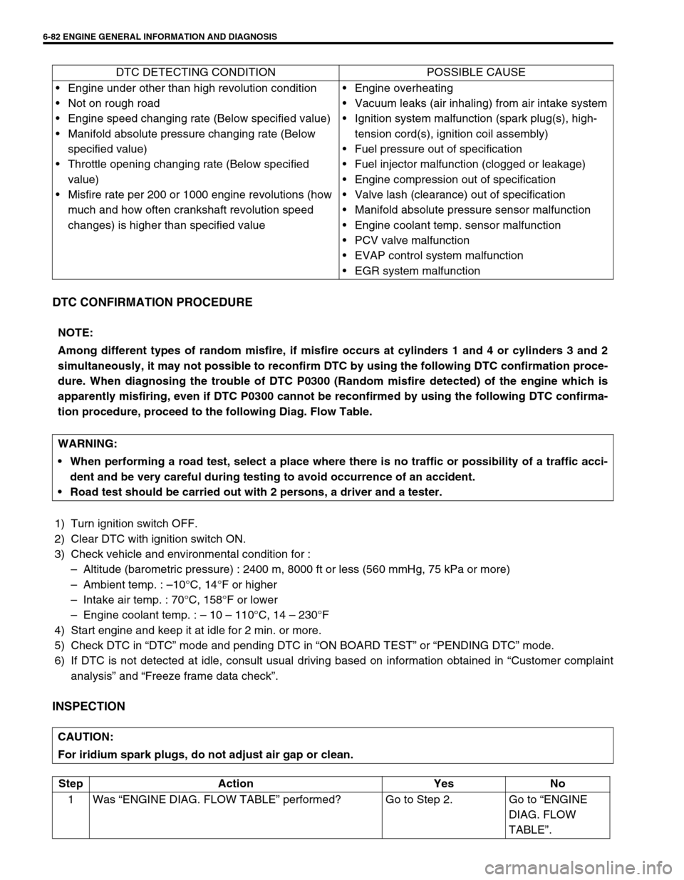
DTC CONFIRMATION PROCEDURE
1) Turn ignition switch OFF.
2) Clear DTC with ignition switch ON.
3) Check vehicle and environmental condition for :
–Altitude (barometric pressure) : 2400 m, 8000 ft or less (560 mmHg, 75 kPa or more)
–Ambient temp. : –10°C, 14°F or higher
–Intake air temp. : 70°C, 158°F or lower
–Engine coolant temp. : – 10 – 110°C, 14 – 230°F
4) Start engine and keep it at idle for 2 min. or more.
5) Check DTC in “DTC” mode and pending DTC in “ON BOARD TEST” or “PENDING DTC” mode.
6) If DTC is not detected at idle, consult usual driving based on information obtained in “Customer complaint
analysis” and “Freeze frame data check”.
INSPECTION
DTC DETECTING CONDITION POSSIBLE CAUSE
Engine under other than high revolution condition
Not on rough road
Engine speed changing rate (Below specified value)
Manifold absolute pressure changing rate (Below
specified value)
Throttle opening changing rate (Below specified
value)
Misfire rate per 200 or 1000 engine revolutions (how
much and how often crankshaft revolution speed
changes) is higher than specified valueEngine overheating
Vacuum leaks (air inhaling) from air intake system
Ignition system malfunction (spark plug(s), high-
tension cord(s), ignition coil assembly)
Fuel pressure out of specification
Fuel injector malfunction (clogged or leakage)
Engine compression out of specification
Valve lash (clearance) out of specification
Manifold absolute pressure sensor malfunction
Engine coolant temp. sensor malfunction
PCV valve malfunction
EVAP control system malfunction
EGR system malfunction
NOTE:
Among different types of random misfire, if misfire occurs at cylinders 1 and 4 or cylinders 3 and 2
simultaneously, it may not possible to reconfirm DTC by using the following DTC confirmation proce-
dure. When diagnosing the trouble of DTC P0300 (Random misfire detected) of the engine which is
apparently misfiring, even if DTC P0300 cannot be reconfirmed by using the following DTC confirma-
tion procedure, proceed to the following Diag. Flow Table.
WARNING:
When performing a road test, select a place where there is no traffic or possibility of a traffic acci-
dent and be very careful during testing to avoid occurrence of an accident.
Road test should be carried out with 2 persons, a driver and a tester.
CAUTION:
For iridium spark plugs, do not adjust air gap or clean.
Step Action Yes No
1Was “ENGINE DIAG. FLOW TABLE” performed? Go to Step 2. Go to “ENGINE
DIAG. FLOW
TABLE”.
Page 452 of 698
ENGINE GENERAL INFORMATION AND DIAGNOSIS 6-83
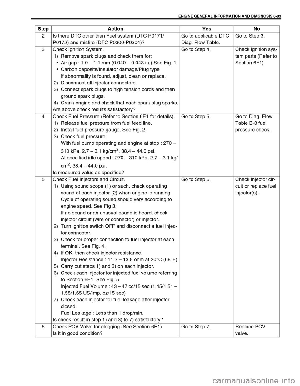
2 Is there DTC other than Fuel system (DTC P0171/
P0172) and misfire (DTC P0300-P0304)?Go to applicable DTC
Diag. Flow Table.Go to Step 3.
3 Check Ignition System.
1) Remove spark plugs and check them for;
Air gap : 1.0 – 1.1 mm (0.040 – 0.043 in.) See Fig. 1.
Carbon deposits/Insulator damage/Plug type
If abnormality is found, adjust, clean or replace.
2) Disconnect all injector connectors.
3) Connect spark plugs to high tension cords and then
ground spark plugs.
4) Crank engine and check that each spark plug sparks.
Are above check results satisfactory?Go to Step 4. Check ignition sys-
tem parts (Refer to
Section 6F1)
4 Check Fuel Pressure (Refer to Section 6E1 for details).
1) Release fuel pressure from fuel feed line.
2) Install fuel pressure gauge. See Fig. 2.
3) Check fuel pressure.
With fuel pump operating and engine at stop : 270 –
310 kPa, 2.7 – 3.1 kg/cm
2, 38.4 – 44.0 psi.
At specified idle speed : 270 – 310 kPa, 2.7 – 3.1 kg/
cm
2, 38.4 – 44.0 psi.
Is measured value as specified?Go to Step 5. Go to Diag. Flow
Table B-3 fuel
pressure check.
5 Check Fuel Injectors and Circuit.
1) Using sound scope (1) or such, check operating
sound of each injector (2) when engine is running.
Cycle of operating sound should very according to
engine speed. See Fig 3.
If no sound or an unusual sound is heard, check
injector circuit (wire or connector) or injector.
2) Turn ignition switch OFF and disconnect a fuel injec-
tor connector.
3) Check for proper connection to fuel injector at each
terminal. See Fig. 4.
4) If OK, then check injector resistance.
Injector Resistance : 11.3 – 13.8 ohm at 20°C (68°F)
5) Carry out steps 1) and 3) on each injector.
6) Check each injector for injected fuel volume referring
to Section 6E1. See Fig. 5.
Injected Fuel Volume : 43 – 47 cc/15 sec (1.45/1.51 –
1.58/1.65 US/Imp. oz/15 sec)
7) Check each injector for fuel leakage after injector
closed.
Fuel Leakage : Less than 1 drop/min.
Is check result in step 1) and 3) to 7) satisfactory?Go to Step 6. Check injector cir-
cuit or replace fuel
injector(s).
6 Check PCV Valve for clogging (See Section 6E1).
Is it in good condition?Go to Step 7. Replace PCV
valve. Step Action Yes No
Page 505 of 698

6A1-4 ENGINE MECHANICAL (M13 ENGINE)
DIAGNOSIS
DIAGNOSIS TABLE
Refer to “ENGINE MECHANICAL DIAGNOSIS TABLE” in Sec-
tion 6.
COMPRESSION CHECK
Check compression pressure on all 4 cylinders as follows:
1) Warm up engine to normal operating temperature.
2) Stop engine after warming up.
3) Remove air cleaner assembly (1), resonator (2) and hoses.
Refer to “AIR CLEANER ASSEMBLY AND RESONATOR”.
4) Remove cylinder head upper cover (1).
5) Disconnect ignition coil couplers (1).
6) Remove ignition coil assemblies (2) with high-tension cord
(3).
7) Remove all spark plugs.
8) Disconnect fuel injector wires (4) at the coupler.NOTE:
After warming up engine, place transmission gear shift
lever in “Neutral” (shift selector lever to “P” range for A/T
model), and set parking brake and block drive wheels.
Page 506 of 698
ENGINE MECHANICAL (M13 ENGINE) 6A1-5
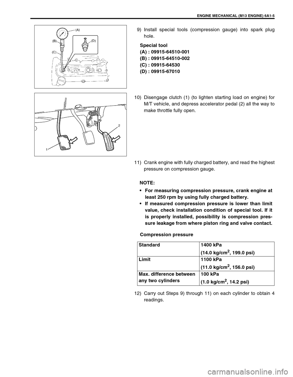
9) Install special tools (compression gauge) into spark plug
hole.
Special tool
(A) : 09915-64510-001
(B) : 09915-64510-002
(C) : 09915-64530
(D) : 09915-67010
10) Disengage clutch (1) (to lighten starting load on engine) for
M/T vehicle, and depress accelerator pedal (2) all the way to
make throttle fully open.
11) Crank engine with fully charged battery, and read the highest
pressure on compression gauge.
Compression pressure
12) Carry out Steps 9) through 11) on each cylinder to obtain 4
readings.
NOTE:
For measuring compression pressure, crank engine at
least 250 rpm by using fully charged battery.
If measured compression pressure is lower than limit
value, check installation condition of special tool. If it
is properly installed, possibility is compression pres-
sure leakage from where piston ring and valve contact.
Standard 1400 kPa
(14.0 kg/cm
2, 199.0 psi)
Limit 1100 kPa
(11.0 kg/cm
2, 156.0 psi)
Max. difference between
any two cylinders100 kPa
(1.0 kg/cm
2, 14.2 psi)
Page 507 of 698
6A1-6 ENGINE MECHANICAL (M13 ENGINE)
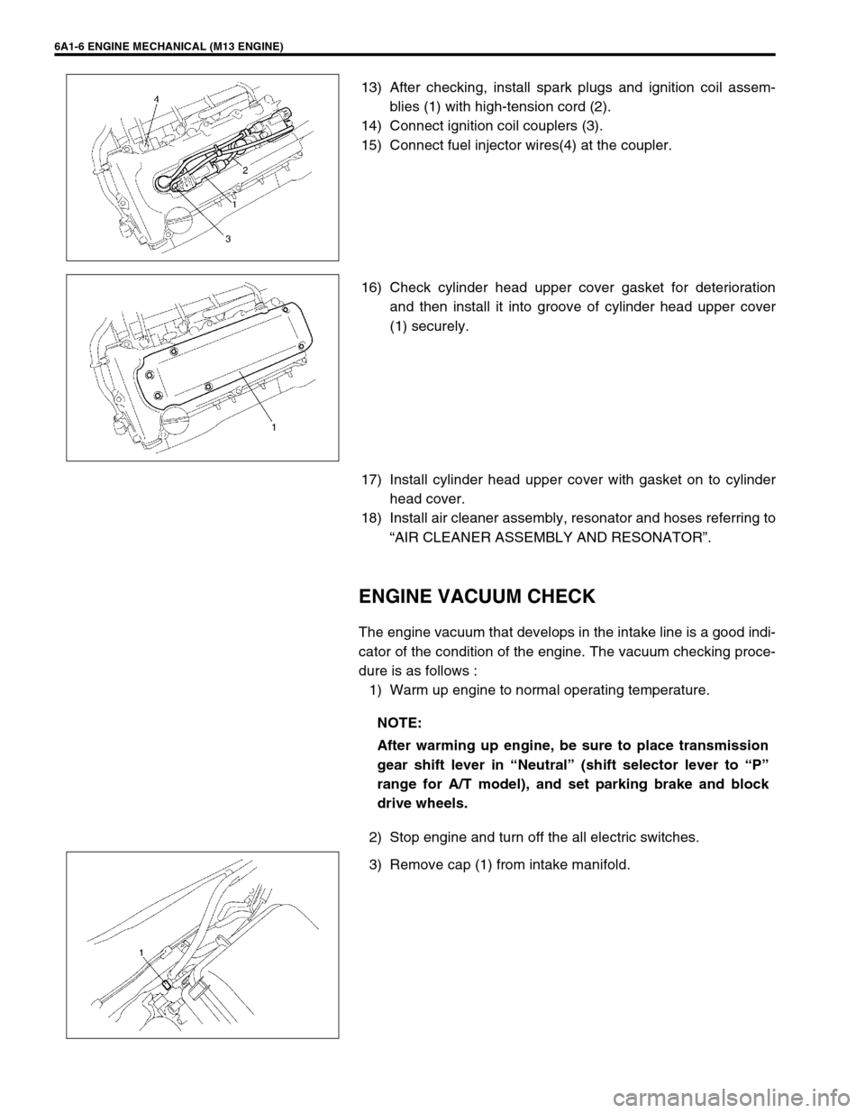
13) After checking, install spark plugs and ignition coil assem-
blies (1) with high-tension cord (2).
14) Connect ignition coil couplers (3).
15) Connect fuel injector wires(4) at the coupler.
16) Check cylinder head upper cover gasket for deterioration
and then install it into groove of cylinder head upper cover
(1) securely.
17) Install cylinder head upper cover with gasket on to cylinder
head cover.
18) Install air cleaner assembly, resonator and hoses referring to
“AIR CLEANER ASSEMBLY AND RESONATOR”.
ENGINE VACUUM CHECK
The engine vacuum that develops in the intake line is a good indi-
cator of the condition of the engine. The vacuum checking proce-
dure is as follows :
1) Warm up engine to normal operating temperature.
2) Stop engine and turn off the all electric switches.
3) Remove cap (1) from intake manifold.
NOTE:
After warming up engine, be sure to place transmission
gear shift lever in “Neutral” (shift selector lever to “P”
range for A/T model), and set parking brake and block
drive wheels.
Page 515 of 698
6A1-14 ENGINE MECHANICAL (M13 ENGINE)
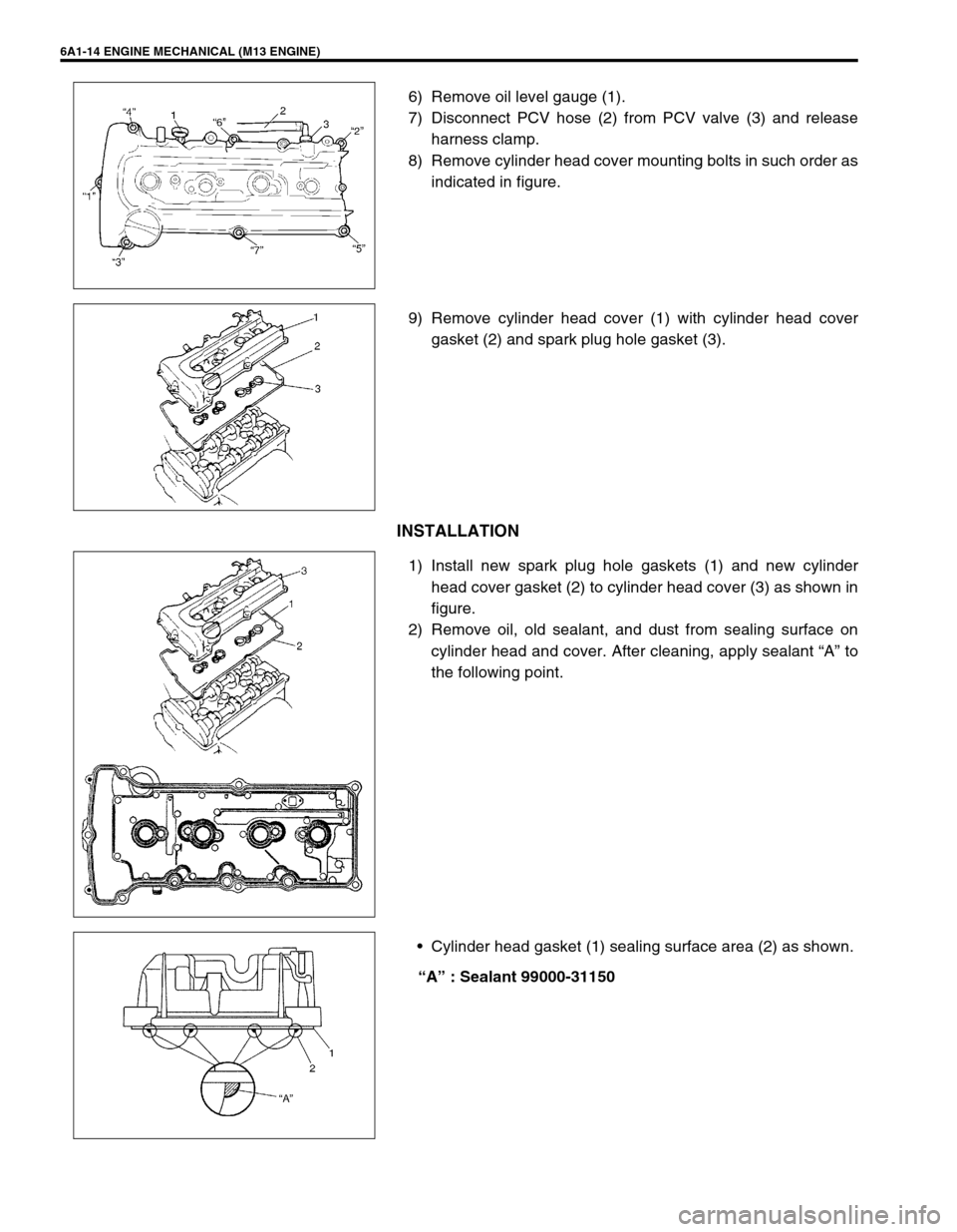
6) Remove oil level gauge (1).
7) Disconnect PCV hose (2) from PCV valve (3) and release
harness clamp.
8) Remove cylinder head cover mounting bolts in such order as
indicated in figure.
9) Remove cylinder head cover (1) with cylinder head cover
gasket (2) and spark plug hole gasket (3).
INSTALLATION
1) Install new spark plug hole gaskets (1) and new cylinder
head cover gasket (2) to cylinder head cover (3) as shown in
figure.
2) Remove oil, old sealant, and dust from sealing surface on
cylinder head and cover. After cleaning, apply sealant “A” to
the following point.
Cylinder head gasket (1) sealing surface area (2) as shown.
“A” : Sealant 99000-31150
Page 516 of 698
ENGINE MECHANICAL (M13 ENGINE) 6A1-15
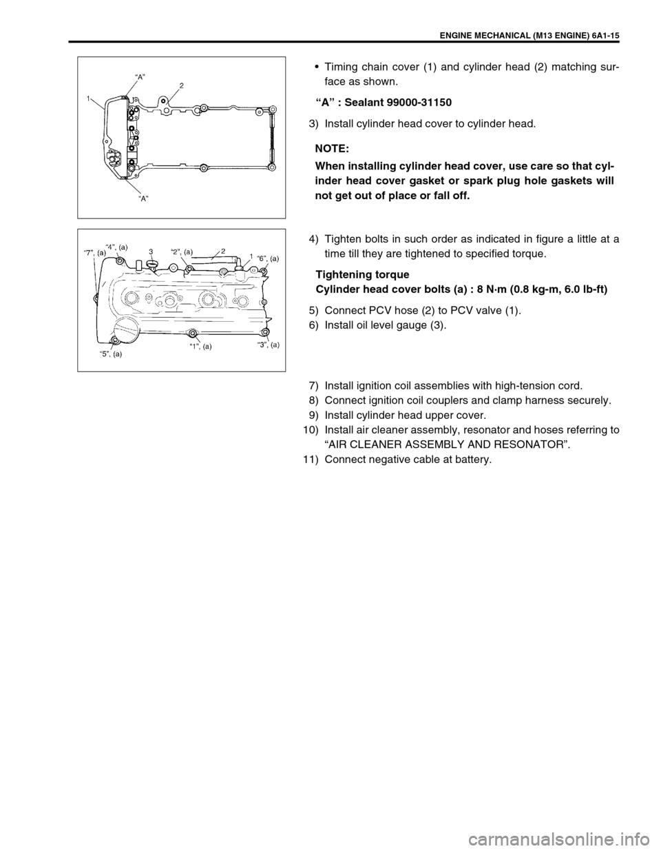
Timing chain cover (1) and cylinder head (2) matching sur-
face as shown.
“A” : Sealant 99000-31150
3) Install cylinder head cover to cylinder head.
4) Tighten bolts in such order as indicated in figure a little at a
time till they are tightened to specified torque.
Tightening torque
Cylinder head cover bolts (a) : 8 N·m (0.8 kg-m, 6.0 lb-ft)
5) Connect PCV hose (2) to PCV valve (1).
6) Install oil level gauge (3).
7) Install ignition coil assemblies with high-tension cord.
8) Connect ignition coil couplers and clamp harness securely.
9) Install cylinder head upper cover.
10) Install air cleaner assembly, resonator and hoses referring to
“AIR CLEANER ASSEMBLY AND RESONATOR”.
11) Connect negative cable at battery.NOTE:
When installing cylinder head cover, use care so that cyl-
inder head cover gasket or spark plug hole gaskets will
not get out of place or fall off.
Page 631 of 698
6E1-10 ENGINE AND EMISSION CONTROL SYSTEM
1. CKP sensor 20. Blank 39. Ignition coil assembly (for No.1 and No.4 spark plugs)
2. CMP sensor 21. A/C switch 40. Ignition coil assembly (for No.2 and No.3 spark plugs)
3. VSS 22. A/C pressure switch 41. Stop lamp switch
4. MAP sensor 23. Immobilizer control module 42. Stop lamp
5. Knock sensor (if equipped) 24. Data link connector 43. Lighting switch
6. TP sensor 25. Injector No.1 44. Position lamp
7. ECT sensor 26. Injector No.2 45. Rear defogger switch
8. IAT sensor 27. Injector No.3 46. Rear defogger
9. Heated oxygen sensor-1 (if equipped) 28. Injector No.4 47. A/C compressor clutch (if equipped)
10. Heated oxygen sensor-2 (if equipped) 29. IAC valve 48. Ignition switch
11. A/C evaporator temp. sensor 30. EVAP canister purge valve 49. Main relay
12. Combination meter 31. Fuel pump relay 50. Transmission range switch (A/T)
13. Fuel level sensor (vehicle with immobilizer
indicator lamp)32. Fuel pump 51. Starting motor
14. TCM 33. Radiator fan relay 52. Shield wire
15. Transmission range switch 34. Radiator fan motor 53. Main fuse
16. ABS control module 35. EGR valve (if equipped) 54. Barometric pressure sensor
17. CO adjusting resistor (if equipped) 36. Malfunction indicator lamp 55. Immobilizer indicator lamp (if equipped)
18. Heater fan motor 37. Tachometer 56. Engine ground
19. Heater fan switch 38. Monitor connector (vehicle without immo-
bilizer indicator lamp)57. Body ground
Page 633 of 698
6E1-12 ENGINE AND EMISSION CONTROL SYSTEM
1. CKP sensor 20. Blank 39. Ignition coil assembly (for No.1 and No.4 spark plugs)
2. CMP sensor 21. A/C switch 40. Ignition coil assembly (for No.2 and No.3 spark plugs)
3. VSS 22. A/C pressure switch 41. Stop lamp switch
4. MAP sensor 23. Immobilizer control module 42. Stop lamp
5. Knock sensor (if equipped) 24. Data link connector 43. Lighting switch
6. TP sensor 25. Injector No.1 44. Position lamp
7. ECT sensor 26. Injector No.2 45. Rear defogger switch
8. IAT sensor 27. Injector No.3 46. Rear defogger
9. Heated oxygen sensor-1 (if equipped) 28. Injector No.4 47. A/C compressor clutch (if equipped)
10. Blank 29. IAC valve 48. Ignition switch
11. A/C evaporator temp. sensor 30. EVAP canister purge valve 49. Main relay
12. Combination meter 31. Fuel pump relay 50. Transmission range switch (A/T)
13. Fuel level sensor (vehicle with immobilizer
indicator lamp)32. Fuel pump 51. Starting motor
14. TCM 33. Radiator fan relay 52. Shield wire
15. Transmission range switch 34. Radiator fan motor 53. Main fuse
16. ABS control module 35. EGR valve (if equipped) 54. Barometric pressure sensor
17. CO adjusting resistor (if equipped) 36. Malfunction indicator lamp 55. Immobilizer indicator lamp (if equipped)
18. Heater fan motor 37. Tachometer 56. Engine ground
19. Heater fan switch 38. Monitor connector (vehicle without immo-
bilizer indicator lamp)57. Body ground
Page 634 of 698
ENGINE AND EMISSION CONTROL SYSTEM 6E1-13
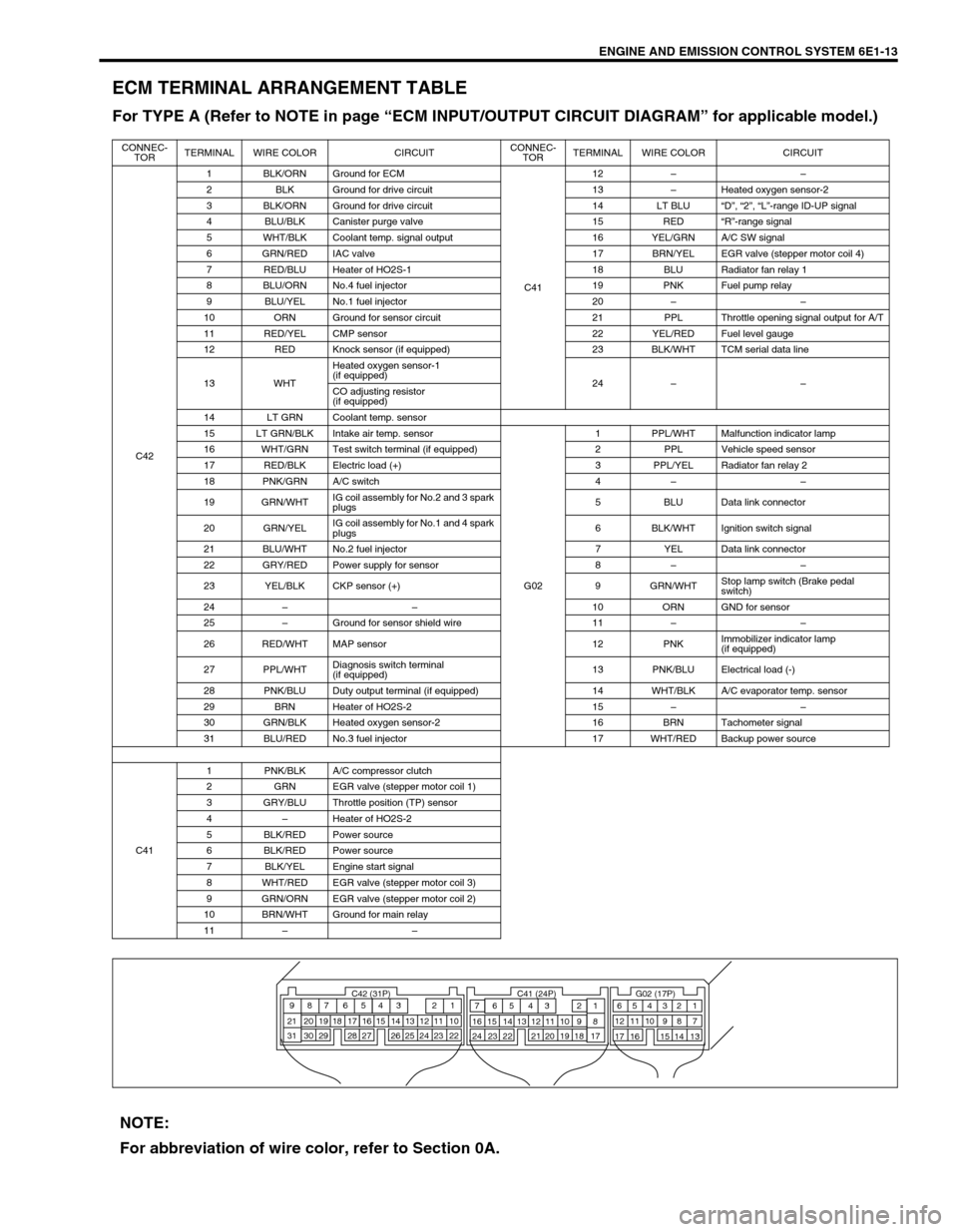
ECM TERMINAL ARRANGEMENT TABLE
For TYPE A (Refer to NOTE in page “ECM INPUT/OUTPUT CIRCUIT DIAGRAM” for applicable model.)
CONNEC-
TORTERMINAL WIRE COLOR CIRCUITCONNEC-
TORTERMINAL WIRE COLOR CIRCUIT
C421 BLK/ORN Ground for ECM
C4112––
2 BLK Ground for drive circuit 13–Heated oxygen sensor-2
3 BLK/ORN Ground for drive circuit 14 LT BLU“D”, “2”, “L”-range ID-UP signal
4 BLU/BLK Canister purge valve 15 RED“R”-range signal
5 WHT/BLK Coolant temp. signal output 16 YEL/GRN A/C SW signal
6 GRN/RED IAC valve 17 BRN/YEL EGR valve (stepper motor coil 4)
7 RED/BLU Heater of HO2S-1 18 BLU Radiator fan relay 1
8 BLU/ORN No.4 fuel injector 19 PNK Fuel pump relay
9 BLU/YEL No.1 fuel injector 20––
10 ORN Ground for sensor circuit 21 PPL Throttle opening signal output for A/T
11 RED/YEL CMP sensor 22 YEL/RED Fuel level gauge
12 RED Knock sensor (if equipped) 23 BLK/WHT TCM serial data line
13 WHTHeated oxygen sensor-1
(if equipped)
24––
CO adjusting resistor
(if equipped)
14 LT GRN Coolant temp. sensor
15 LT GRN/BLK Intake air temp. sensor
G021 PPL/WHT Malfunction indicator lamp
16 WHT/GRN Test switch terminal (if equipped) 2 PPL Vehicle speed sensor
17 RED/BLK Electric load (+) 3 PPL/YEL Radiator fan relay 2
18 PNK/GRN A/C switch 4––
19 GRN/WHTIG coil assembly for No.2 and 3 spark
plugs5 BLU Data link connector
20 GRN/YELIG coil assembly for No.1 and 4 spark
plugs6 BLK/WHT Ignition switch signal
21 BLU/WHT No.2 fuel injector 7 YEL Data link connector
22 GRY/RED Power supply for sensor 8––
23 YEL/BLK CKP sensor (+) 9 GRN/WHTStop lamp switch (Brake pedal
switch)
24––10 ORN GND for sensor
25–Ground for sensor shield wire 11––
26 RED/WHT MAP sensor 12 PNKImmobilizer indicator lamp
(if equipped)
27 PPL/WHTDiagnosis switch terminal
(if equipped)13 PNK/BLU Electrical load (-)
28 PNK/BLU Duty output terminal (if equipped) 14 WHT/BLK A/C evaporator temp. sensor
29 BRN Heater of HO2S-2 15––
30 GRN/BLK Heated oxygen sensor-2 16 BRN Tachometer signal
31 BLU/RED No.3 fuel injector 17 WHT/RED Backup power source
C411 PNK/BLK A/C compressor clutch
2 GRN EGR valve (stepper motor coil 1)
3 GRY/BLU Throttle position (TP) sensor
4–Heater of HO2S-2
5 BLK/RED Power source
6 BLK/RED Power source
7 BLK/YEL Engine start signal
8 WHT/RED EGR valve (stepper motor coil 3)
9 GRN/ORN EGR valve (stepper motor coil 2)
10 BRN/WHT Ground for main relay
11––
C42 (31P) C41 (24P) G02 (17P)1 2 3 4 5 6 7 8 9
10 11 12 13 14 15 16 17 18 19 20 21
22 23 24 25 26 28 27 29 30 315 6
1 2 3 4 5 6 7
11 12
9 10 11 13 12 14 15 16
16 171 2
7 8
13 14 3 4
9 10
15 17 188
19 20 21 22 23 24
NOTE:
For abbreviation of wire color, refer to Section 0A.