horn SUZUKI SWIFT 2000 1.G RG413 Service Workshop Manual
[x] Cancel search | Manufacturer: SUZUKI, Model Year: 2000, Model line: SWIFT, Model: SUZUKI SWIFT 2000 1.GPages: 698, PDF Size: 16.01 MB
Page 177 of 698
3C-4 STEERING WHEEL AND COLUMN
HANDLING AND STORAGE
For handling and storage, refer to “HANDLING AND STORAGE” under “SERVICE PRECAUTIONS” in Section
10B.
DISPOSAL
For disposal, refer to “DISPOSAL” under “SERVICE PRECAUTIONS” in Section 10B.
DRIVER AIR BAG (INFLATOR) MODULE
REMOVAL
1) Disconnect negative cable at battery.
2) Disable air bag system. Refer to “DISABLING AIR BAG
SYSTEM” under “SERVICE PRECAUTIONS” in Section
10B.
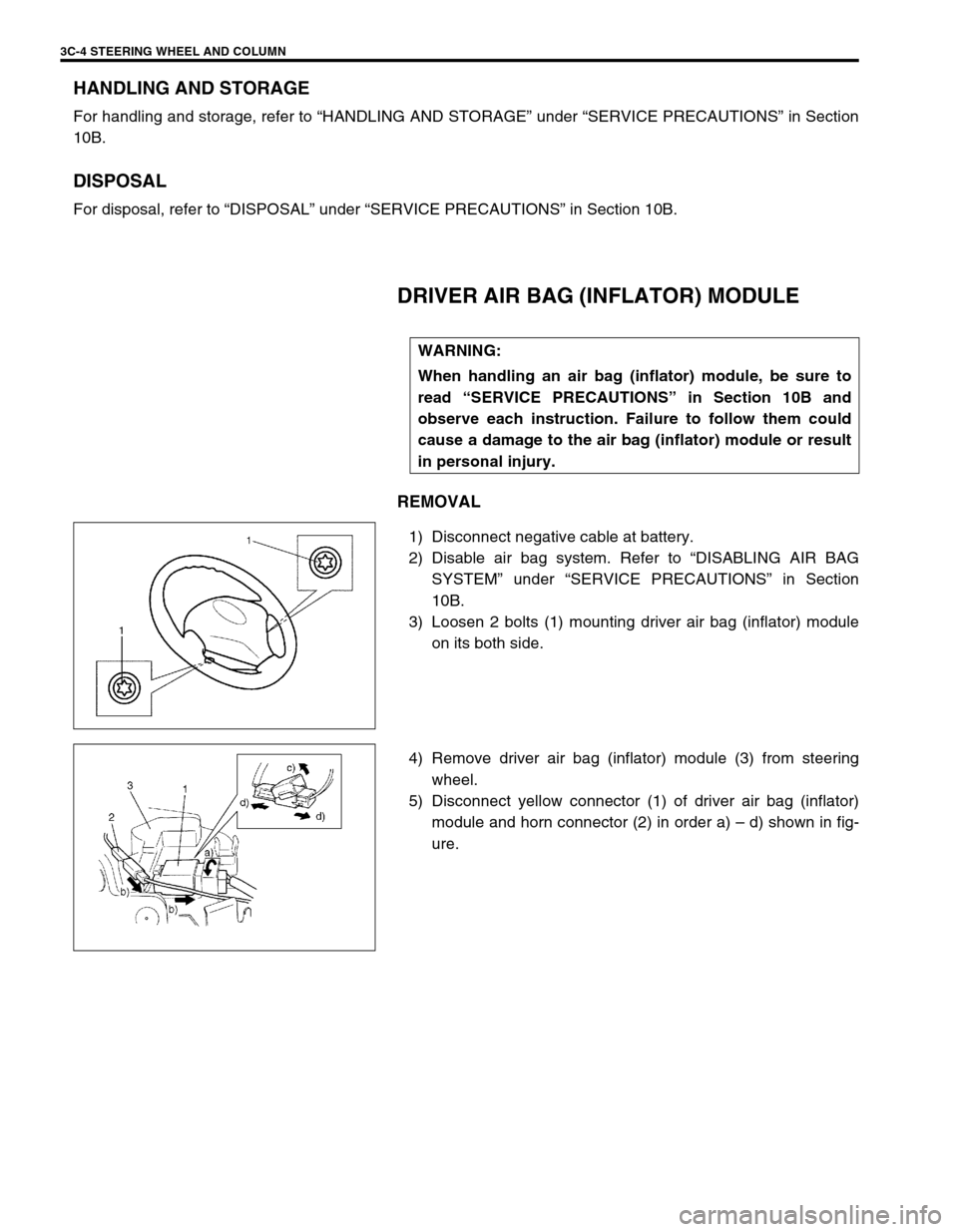
3) Loosen 2 bolts (1) mounting driver air bag (inflator) module
on its both side.
4) Remove driver air bag (inflator) module (3) from steering
wheel.
5) Disconnect yellow connector (1) of driver air bag (inflator)
module and horn connector (2) in order a) – d) shown in fig-
ure. WARNING:
When handling an air bag (inflator) module, be sure to
read “SERVICE PRECAUTIONS” in Section 10B and
observe each instruction. Failure to follow them could
cause a damage to the air bag (inflator) module or result
in personal injury.
Page 178 of 698
STEERING WHEEL AND COLUMN 3C-5
INSPECTION
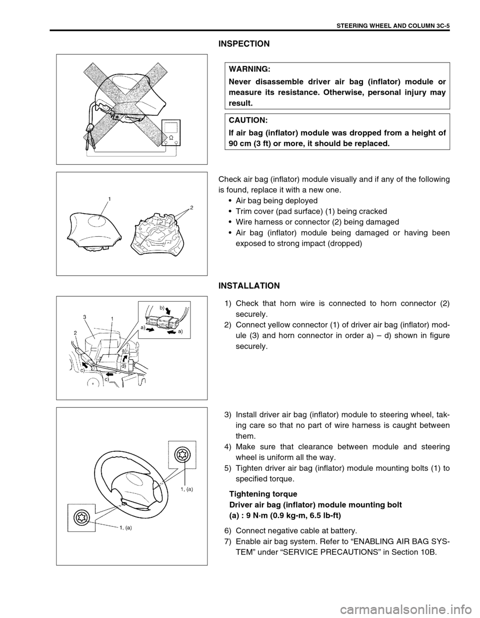
Check air bag (inflator) module visually and if any of the following
is found, replace it with a new one.
Air bag being deployed
Trim cover (pad surface) (1) being cracked
Wire harness or connector (2) being damaged
Air bag (inflator) module being damaged or having been
exposed to strong impact (dropped)
INSTALLATION
1) Check that horn wire is connected to horn connector (2)
securely.
2) Connect yellow connector (1) of driver air bag (inflator) mod-
ule (3) and horn connector in order a) – d) shown in figure
securely.
3) Install driver air bag (inflator) module to steering wheel, tak-
ing care so that no part of wire harness is caught between
them.
4) Make sure that clearance between module and steering
wheel is uniform all the way.
5) Tighten driver air bag (inflator) module mounting bolts (1) to
specified torque.
Tightening torque
Driver air bag (inflator) module mounting bolt
(a) : 9 N·m (0.9 kg-m, 6.5 lb-ft)
6) Connect negative cable at battery.
7) Enable air bag system. Refer to “ENABLING AIR BAG SYS-
TEM” under “SERVICE PRECAUTIONS” in Section 10B. WARNING:
Never disassemble driver air bag (inflator) module or
measure its resistance. Otherwise, personal injury may
result.
CAUTION:
If air bag (inflator) module was dropped from a height of
90 cm (3 ft) or more, it should be replaced.
Page 182 of 698
STEERING WHEEL AND COLUMN 3C-9
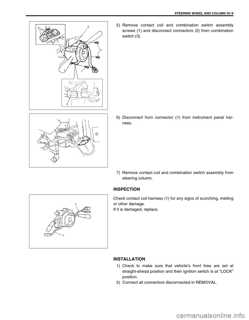
5) Remove contact coil and combination switch assembly
screws (1) and disconnect connectors (2) from combination
switch (3).
6) Disconnect horn connector (1) from instrument panel har-
ness.
7) Remove contact coil and combination switch assembly from
steering column.
INSPECTION
Check contact coil harness (1) for any signs of scorching, melting
or other damage.
If it is damaged, replace.
INSTALLATION
1) Check to make sure that vehicle’s front tires are set at
straight-ahead position and then ignition switch is at “LOCK”
position.
2) Connect all connectors disconnected in REMOVAL.
Page 186 of 698
STEERING WHEEL AND COLUMN 3C-13
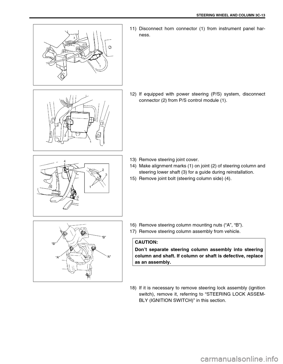
11) Disconnect horn connector (1) from instrument panel har-
ness.
12) If equipped with power steering (P/S) system, disconnect
connector (2) from P/S control module (1).
13) Remove steering joint cover.
14) Make alignment marks (1) on joint (2) of steering column and
steering lower shaft (3) for a guide during reinstallation.
15) Remove joint bolt (steering column side) (4).
16) Remove steering column mounting nuts (“A”, “B”).
17) Remove steering column assembly from vehicle.
18) If it is necessary to remove steering lock assembly (ignition
switch), remove it, referring to “STEERING LOCK ASSEM-
BLY (IGNITION SWITCH)” in this section.
CAUTION:
Don’t separate steering column assembly into steering
column and shaft. If column or shaft is defective, replace
as an assembly.
Page 187 of 698
3C-14 STEERING WHEEL AND COLUMN
INSPECTION
INSTALLATION
1) Be sure that front wheels and steering wheel are in straight
forward state.
If steering lock assembly (ignition switch) is removed, install
it, referring to “STEERING LOCK ASSEMBLY (IGNITION
SWITCH)” in this section.
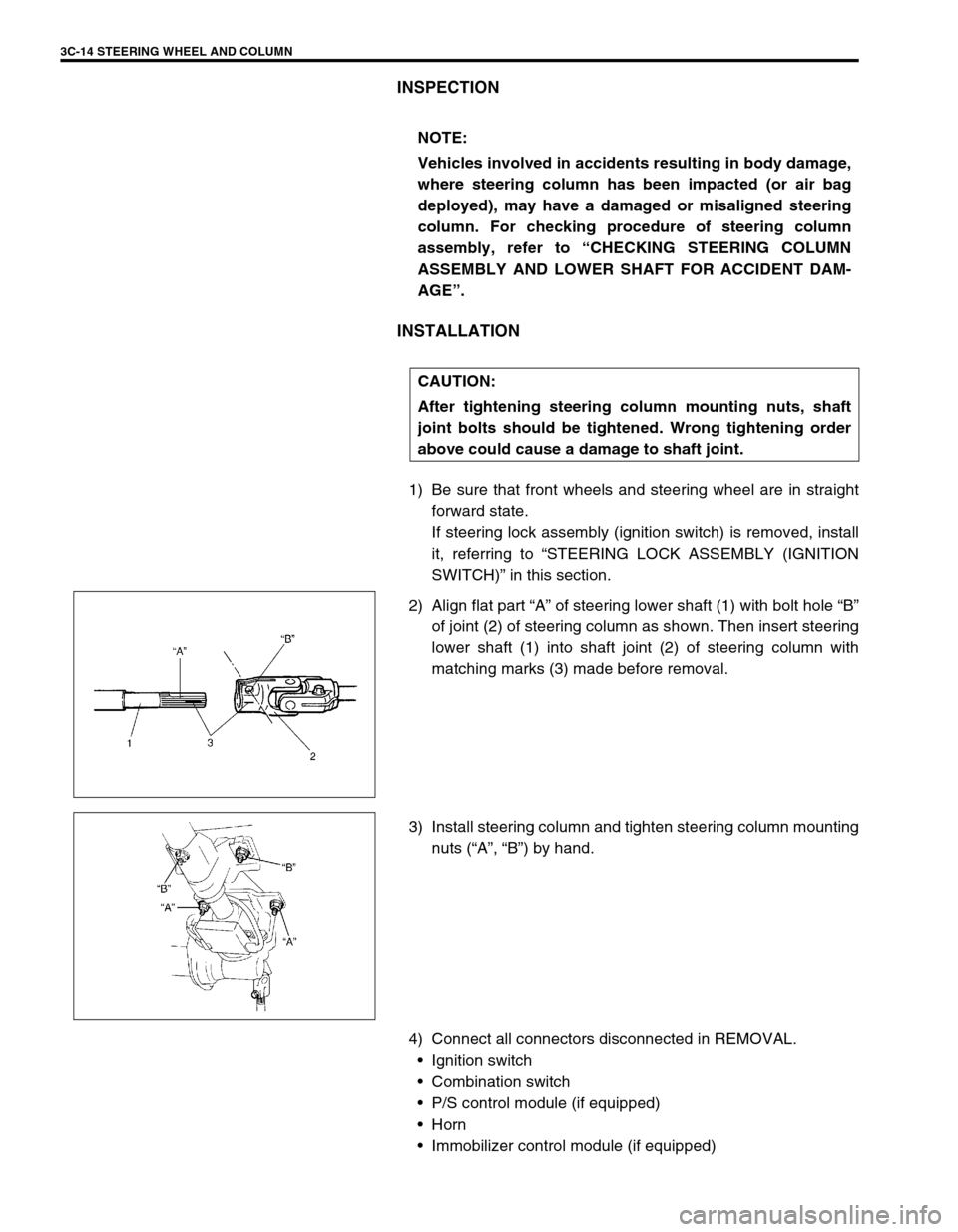
2) Align flat part “A” of steering lower shaft (1) with bolt hole “B”
of joint (2) of steering column as shown. Then insert steering
lower shaft (1) into shaft joint (2) of steering column with
matching marks (3) made before removal.
3) Install steering column and tighten steering column mounting
nuts (“A”, “B”) by hand.
4) Connect all connectors disconnected in REMOVAL.
Ignition switch
Combination switch
P/S control module (if equipped)
Horn
Immobilizer control module (if equipped) NOTE:
Vehicles involved in accidents resulting in body damage,
where steering column has been impacted (or air bag
deployed), may have a damaged or misaligned steering
column. For checking procedure of steering column
assembly, refer to “CHECKING STEERING COLUMN
ASSEMBLY AND LOWER SHAFT FOR ACCIDENT DAM-
AGE”.
CAUTION:
After tightening steering column mounting nuts, shaft
joint bolts should be tightened. Wrong tightening order
above could cause a damage to shaft joint.