air bag SUZUKI SWIFT 2000 1.G RG413 Service User Guide
[x] Cancel search | Manufacturer: SUZUKI, Model Year: 2000, Model line: SWIFT, Model: SUZUKI SWIFT 2000 1.GPages: 698, PDF Size: 16.01 MB
Page 52 of 698
HEATER AND VENTILATION 1A-1
6F1
6F2
6G
1A
6K
7A
7A1
7B1
7C1
7D
7E
7F
8A
8B
8C
8D
8E
9
10
10A
10B
SECTION 1A
HEATER AND VENTILATION
CONTENTS
GENERAL DESCRIPTION .............................. 1A-2
DIAGNOSIS ..................................................... 1A-3
DIAGNOSIS TABLE ..................................... 1A-3
WIRING CIRCUIT ........................................ 1A-4
ON-VEHICLE SERVICE .................................. 1A-5
HEATER UNIT ............................................. 1A-5BLOWER FAN MOTOR ............................... 1A-7
BLOWER FAN MOTOR RESISTOR ........... 1A-8
HEATER CONTROL ASSEMBLY ............... 1A-9
AIR INLET BOX ......................................... 1A-12
VENTILATION LOUVER............................ 1A-13
REQUIRED SERVICE MATERIALS ............. 1A-14
WARNING:
For vehicles equipped with Supplement Restraint (Air Bag) System
Service on and around the air bag system components or wiring must be performed only by an
authorized SUZUKI dealer. Refer to “Air Bag System Components and Wiring Location View” under
“General Description” in Section 10B in order to confirm whether you are performing service on or
near the air bag system components or wiring. Please observe all WARNINGS and “Service Precau-
tions” under “On-Vehicle Service” in Section 10B before performing service on or around the air
bag system components or wiring. Failure to follow WARNINGS could result in unintentional activa-
tion of the system or could render the system inoperative. Either or these two conditions may result
in severe injury.
Technical service work must be started at least 90 seconds after the ignition switch is turned to the
“LOCK” position and the negative cable is disconnected from the battery. Otherwise, the system
may be activated by reserve energy in the Sensing and Diagnostic Module (SDM).
NOTE:
The link mechanism of the heater varies depending on the specifications.
Page 63 of 698
1A-12 HEATER AND VENTILATION
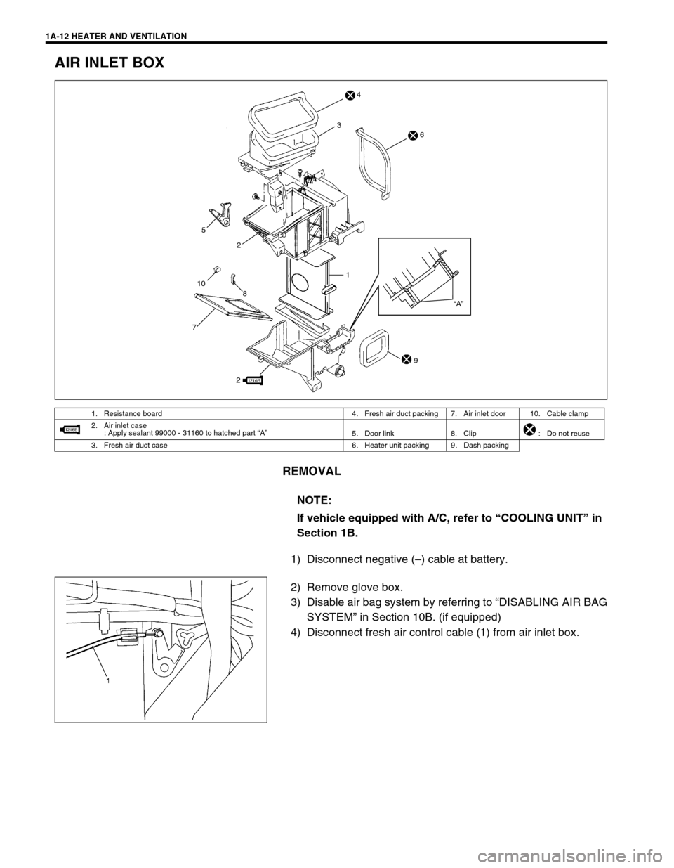
AIR INLET BOX
REMOVAL
1) Disconnect negative (–) cable at battery.
2) Remove glove box.
3) Disable air bag system by referring to “DISABLING AIR BAG
SYSTEM” in Section 10B. (if equipped)
4) Disconnect fresh air control cable (1) from air inlet box.
1. Resistance board 4. Fresh air duct packing 7. Air inlet door 10. Cable clamp
2. Air inlet case
: Apply sealant 99000 - 31160 to hatched part “A”
5. Door link 8. Clip : Do not reuse
3. Fresh air duct case 6. Heater unit packing 9. Dash packing
NOTE:
If vehicle equipped with A/C, refer to “COOLING UNIT” in
Section 1B.
1
72
8 1053
“A”
2
4
6
9
Page 64 of 698

HEATER AND VENTILATION 1A-13
5) Remove air inlet box mounting nuts (1) and screws (2).
6) Remove air inlet box (3).
INSTALLATION
Reverse removal procedure to install air inlet box noting the fol-
lowing instructions.
Adjust fresh air control cable referring to “INSTALLATION”
under “HEATER CONTROL ASSEMBLY” in this section.
Enable air bag system by referring to “ENABLING AIR BAG
SYSTEM” in Section 10B. (if equipped)
VENTILATION LOUVER
REMOVAL
1) Remove ventilation louver (1) as shown in figure.
2) Remove ventilation louver holder (1) from ventilation louver
(2).
2: Rag
Page 66 of 698
AIR CONDITIONING (OPTIONAL) 1B-1
6F1
6F2
6G
1B
7A
7A1
7B1
7C1
7D
7E
7F
8A
8B
8C
8D
8E
9
10
10A
10B
SECTION 1B
AIR CONDITIONING (OPTIONAL)
CONTENTS
GENERAL DESCRIPTION .............................. 1B-3
REFRIGERANT CIRCULATION .................. 1B-3
REFRIGERANT TYPE ................................. 1B-3
MAJOR COMPONENTS AND
LOCATION ................................................... 1B-4
DIAGNOSIS ..................................................... 1B-5
GENERAL DIAGNOSIS TABLE ................... 1B-5
ABNORMAL NOISE DIAGNOSIS ................ 1B-7
QUICKLY CHECKING OF REFRIGERANT
CHARGE ...................................................... 1B-9
PERFORMANCE DIAGNOSIS .................. 1B-10
PERFORMANCE DIAGNOSIS TABLE .. 1B-12
DETAIL DIAGNOSIS TABLE (AMBIENT
TEMPERATURE AT 30°C (86°F)) ......... 1B-13
COMPRESSOR DRIVE BELT ................... 1B-15ELECTRICAL DIAGNOSIS ........................... 1B-16
WIRING DIAGRAM .................................... 1B-16
A/C SYSTEM INSPECTION OF ECM AND
ITS CIRCUITS ........................................... 1B-17
REFRIGERANT RECOVERY, EVACUATING
AND CHARGING........................................... 1B-20
OPERATION PROCEDURE FOR
REFRIGERANT CHARGING ..................... 1B-20
RECOVERY ............................................... 1B-21
REPLENISHING COMPRESSOR OIL ...... 1B-21
EVACUATING............................................ 1B-22
EVACUATING PROCEDURE ................ 1B-22
CHECKING SYSTEM FOR PRESSURE
LEAKS.................................................... 1B-23
CHARGING................................................ 1B-24
CHARGING PROCEDURE .................... 1B-24 WARNING:
For vehicles equipped with Supplemental Restraint (Air Bag) System :
Service on and around the air bag system components or wiring must be performed only by an
authorized SUZUKI dealer. Refer to “Air Bag System Components and Wiring Location View” under
“General Description” in air bag system section in order to confirm whether you are performing ser-
vice on or near the air bag system components or wiring. Please observe all WARNINGS and “Ser-
vice Precautions” under “On-Vehicle Service” in air bag system section before performing service
on or around the air bag system components or wiring. Failure to follow WARNINGS could result in
unintentional activation of the system or could render the system inoperative. Either of these two
conditions may result in severe injury.
Technical service work must be started at least 90 seconds after the ignition switch is turned to the
“LOCK” position and the negative cable is disconnected from the battery. Otherwise, the system
may be activated by reserve energy in the Sensing and Diagnostic Module (SDM).
CAUTION:
The air conditioning system of this vehicle uses refrigerant HFC-134a (R-134a).
None of refrigerant, compressor oil and component parts is interchangeable between two types of
A/C : one using refrigerant HFC-134a (R-134a) and the other using refrigerant CFC-12 (R-12).
Be sure to check which refrigerant is used before any service work including inspection and mainte-
nance. For identification between these two types, refer to “REFRIGERANT TYPE” in this section.
When replenishing or changing refrigerant and compressor oil and when replacing parts, make sure
that the material or the part to be used is appropriate to the A/C installed in the vehicle being serviced.
Use of incorrect one will result in leakage of refrigerant, damage in parts or other faulty condition.
NOTE:
For basic servicing method of the air conditioning system that is not described in this section, refer to
“AIR CONDITIONING BASIC MANUAL (Part number : 99520-02130)”.
Page 95 of 698
1B-30 AIR CONDITIONING (OPTIONAL)
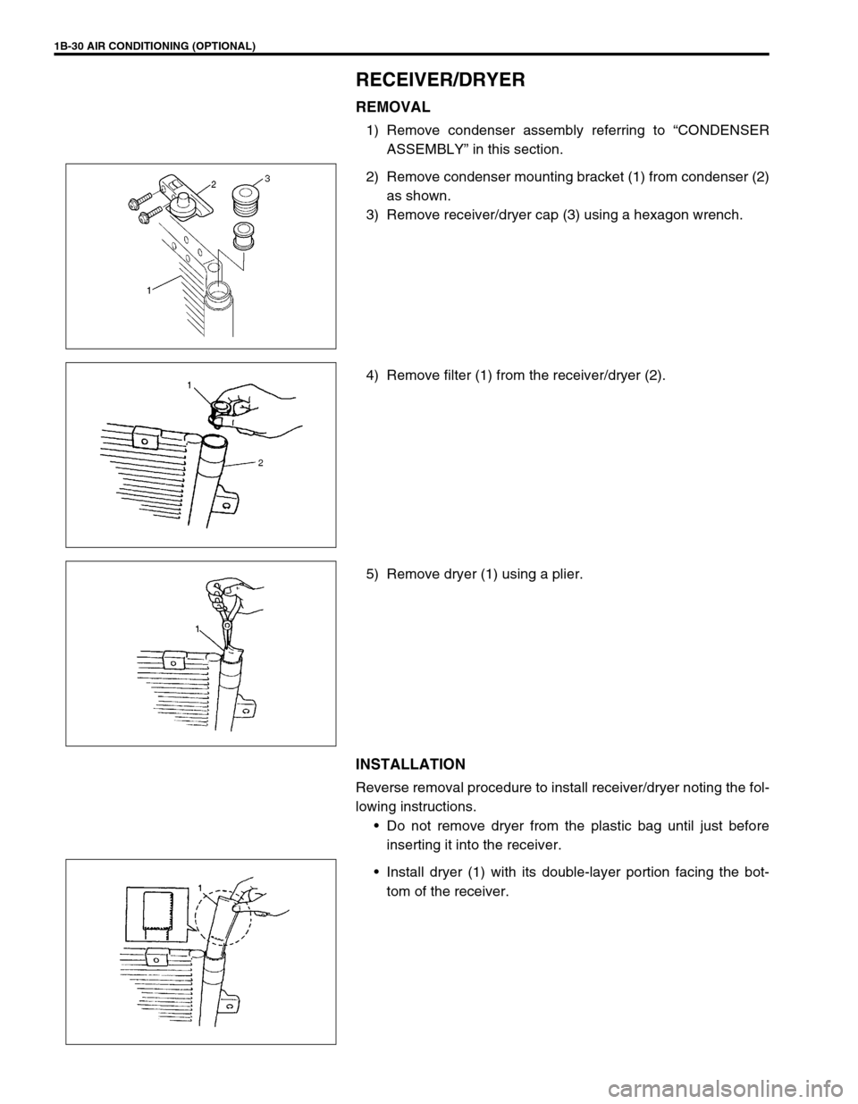
RECEIVER/DRYER
REMOVAL
1) Remove condenser assembly referring to “CONDENSER
ASSEMBLY” in this section.
2) Remove condenser mounting bracket (1) from condenser (2)
as shown.
3) Remove receiver/dryer cap (3) using a hexagon wrench.
4) Remove filter (1) from the receiver/dryer (2).
5) Remove dryer (1) using a plier.
INSTALLATION
Reverse removal procedure to install receiver/dryer noting the fol-
lowing instructions.
Do not remove dryer from the plastic bag until just before
inserting it into the receiver.
Install dryer (1) with its double-layer portion facing the bot-
tom of the receiver.
Page 122 of 698
MANUAL RACK AND PINION 3B-1
6F1
6F2
6G
6H
7A
3B
7C1
7D
7E
7F
8A
8B
8C
8D
8E
9
10
10A
10B
SECTION 3B
MANUAL RACK AND PINION
CONTENTS
GENERAL DESCRIPTION .............................. 3B-2
DIAGNOSIS ..................................................... 3B-3
ON-VEHICLE SERVICE .................................. 3B-4
LUBRICATION ............................................. 3B-4
TIE ROD END .............................................. 3B-6
MANUAL RACK AND PINION ASSEMBLY
(STEERING GEAR CASE) .......................... 3B-7
RACK BOOT/TIE ROD .............................. 3B-10STEERING RACK PLUNGER ................... 3B-12
STEERING PINION ................................... 3B-14
STEERING RACK...................................... 3B-15
PINION BEARING ..................................... 3B-17
RACK BUSHING ........................................ 3B-18
REQUIRED SERVICE MATERIAL................ 3B-19
SPECIAL TOOL ............................................ 3B-20
WARNING:
For vehicles equipped with a Air Bag System
Service on or around air bag system components or wiring must be performed only by an autho-
rized suzuki dealer. Please observe all WARNINGS and CAUTIONS in SECTION 10B and Precau-
tions, Air Bag System Components and Wiring Location view in Section 10B before performing
service on or around air bag system components or wiring. Failure to follow WARNINGS could
result in unintended activation of the system or could render the system inoperative. Either of these
two conditions may result in severe injury.
Technical service work must be started at least 90 seconds after the ignition switch is turned to the
“LOCK” position and the negative cable is disconnected from the battery. Otherwise, the system
may be deployed by reserve energy in the Sensing and Diagnostic Module (SDM).
NOTE:
All steering gear fasteners are important attaching parts in that they could affect the performance of
vital parts and systems, and/or could result in major repair expense. They must be replaced with one
of the same part number or with an equivalent part if replacement becomes necessary. Do not use a
replacement part of lesser quality or substitute design. Torque values must be used as specified dur-
ing reassembly to assure proper retention of these parts.
Page 128 of 698
MANUAL RACK AND PINION 3B-7
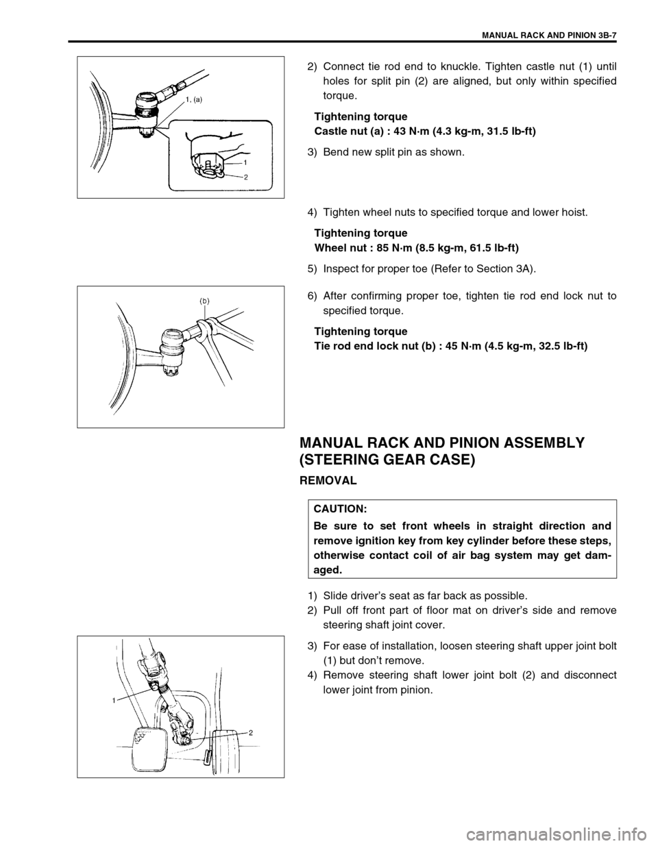
2) Connect tie rod end to knuckle. Tighten castle nut (1) until
holes for split pin (2) are aligned, but only within specified
torque.
Tightening torque
Castle nut (a) : 43 N·m (4.3 kg-m, 31.5 lb-ft)
3) Bend new split pin as shown.
4) Tighten wheel nuts to specified torque and lower hoist.
Tightening torque
Wheel nut : 85 N·m (8.5 kg-m, 61.5 lb-ft)
5) Inspect for proper toe (Refer to Section 3A).
6) After confirming proper toe, tighten tie rod end lock nut to
specified torque.
Tightening torque
Tie rod end lock nut (b) : 45 N·m (4.5 kg-m, 32.5 lb-ft)
MANUAL RACK AND PINION ASSEMBLY
(STEERING GEAR CASE)
REMOVAL
1) Slide driver’s seat as far back as possible.
2) Pull off front part of floor mat on driver’s side and remove
steering shaft joint cover.
3) For ease of installation, loosen steering shaft upper joint bolt
(1) but don’t remove.
4) Remove steering shaft lower joint bolt (2) and disconnect
lower joint from pinion.
CAUTION:
Be sure to set front wheels in straight direction and
remove ignition key from key cylinder before these steps,
otherwise contact coil of air bag system may get dam-
aged.
Page 142 of 698
ELECTRICAL POWER STEERING (P/S) SYSTEM 3B1-1
6F1
6F2
6G
6H
6K
7A
7A1
3B1
7D
7E
7F
8A
8B
8C
8D
8E
9
10
10A
10B
SECTION 3B1
ELECTRICAL POWER STEERING (P/S) SYSTEM
CONTENTS
GENERAL DESCRIPTION .............................3B1-2
SYSTEM COMPONENTS ........................... 3B1-2
WIRING DIAGRAM ..................................... 3B1-3
DIAGNOSIS ....................................................3B1-4
ON-BOARD DIAGNOSTIC SYSTEM .......... 3B1-4
PRECAUTIONS IN DIAGNOSING
TROUBLES ................................................. 3B1-4
SYSTEM CHECK FLOW TABLE ................ 3B1-5
MALFUNCTION INDICATOR LAMP
(“EPS” WARNING LAMP) CHECK.............. 3B1-7
DTC CHECK ............................................... 3B1-8
DTC CLEARANCE ...................................... 3B1-9
SERIAL DATA LINK CIRCUIT CHECK ..... 3B1-10
DTC TABLE .............................................. 3B1-11
TABLE A - MALFUNCTION INDICATOR
LAMP DOES NOT COME ON AT
IGNITION SWITCH ON BUT LEAVING
ENGINE OFF ............................................ 3B1-13
TABLE B - MALFUNCTION INDICATOR
LAMP FLASHES AT IGNITION SWITCH
ON ............................................................. 3B1-15
TABLE C - MALFUNCTION INDICATOR
LAMP DOES NOT FLASH, JUST
REMAINS ON OR JUST REMAINS OFF
EVEN WITH DIAGNOSIS SWITCH
TERMINAL GROUNDED .......................... 3B1-15
DTC C1111 (DTC No.11) TORQUE
SENSOR MAIN CIRCUIT FAILURE ......... 3B1-16
DTC C1113 (DTC No.13) TORQUE
SENSOR MAIN AND SUB CIRCUIT
FAILURE ................................................... 3B1-16DTC C1115 (DTC No.15) TORQUE
SENSOR SUB CIRCUIT FAILURE........... 3B1-16
DTC C1114 (DTC No.14) TORQUE
SENSOR 5V POWER SUPPLY CIRCUIT
FAILURE ................................................... 3B1-17
DTC C1116 (DTC No.16) TORQUE
SENSOR 8V POWER SUPPLY CIRCUIT
FAILURE ................................................... 3B1-18
DTC C1121/C1123/C1124
(DTC No.21/23/24) VSS CIRCUIT
FAILURE ................................................... 3B1-19
DTC C1122 (DTC No.22) ENGINE
SPEED SIGNAL CIRCUIT FAILURE ........ 3B1-20
DTC C1141/C1142/C1143/C1144/C1145
(DTC No.41/42/43/44/45) MOTOR
CIRCUIT FAILURE ................................... 3B1-21
DTC C1151 (DTC No.51) CLUTCH
CIRCUIT FAILURE ................................... 3B1-22
DTC C1153(DTC No.53) P/S CONTROL
MODULE POWER SUPPLY CIRCUIT
FAILURE ................................................... 3B1-24
DTC C1152/C1154/C1155
(DTC No.52/54/55) P/S CONTROL
MODULE FAILURE .................................. 3B1-24
TROUBLE DIAGNOSIS (FOR TROUBLE
NOT INDICATED BY ON BOARD
DIAGNOSTIC SYSTEM)........................... 3B1-25
INSPECTION OF P/S CONTROL
MODULE AND ITS CIRCUITS ................. 3B1-26
STEERING WHEEL PLAY
INSPECTION ............................................ 3B1-28 WARNING:
For vehicles equipped with Supplemental Restraint (Air Bag) System :
Service on and around the air bag system components or wiring must be performed only by an
authorized SUZUKI dealer. Refer to “Air Bag System Components and Wiring Location View” under
“General Description” in air bag system section in order to confirm whether you are performing ser-
vice on or near the air bag system components or wiring. Please observe all WARNINGS and “Ser-
vice Precautions” under “On-Vehicle Service” in air bag system section before performing service
on or around the air bag system components or wiring. Failure to follow WARNINGS could result in
unintentional activation of the system or could render the system inoperative. Either of these two
conditions may result in severe injury.
Technical service work must be started at least 90 seconds after the ignition switch is turned to the
“LOCK” position and the negative cable is disconnected from the battery. Otherwise, the system
may be activated by reserve energy in the Sensing and Diagnostic Module (SDM).
Page 169 of 698
3B1-28 ELECTRICAL POWER STEERING (P/S) SYSTEM
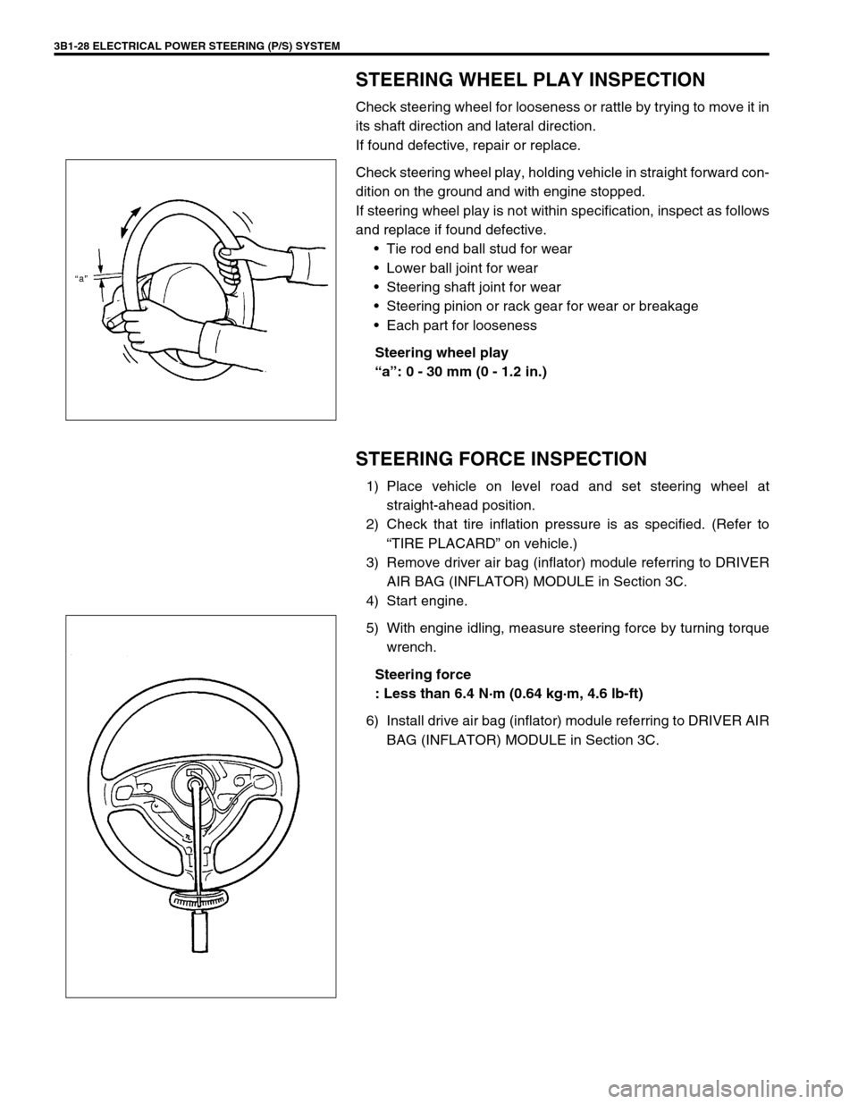
STEERING WHEEL PLAY INSPECTION
Check steering wheel for looseness or rattle by trying to move it in
its shaft direction and lateral direction.
If found defective, repair or replace.
Check steering wheel play, holding vehicle in straight forward con-
dition on the ground and with engine stopped.
If steering wheel play is not within specification, inspect as follows
and replace if found defective.
Tie rod end ball stud for wear
Lower ball joint for wear
Steering shaft joint for wear
Steering pinion or rack gear for wear or breakage
Each part for looseness
Steering wheel play
“a”: 0 - 30 mm (0 - 1.2 in.)
STEERING FORCE INSPECTION
1) Place vehicle on level road and set steering wheel at
straight-ahead position.
2) Check that tire inflation pressure is as specified. (Refer to
“TIRE PLACARD” on vehicle.)
3) Remove driver air bag (inflator) module referring to DRIVER
AIR BAG (INFLATOR) MODULE in Section 3C.
4) Start engine.
5) With engine idling, measure steering force by turning torque
wrench.
Steering force
: Less than 6.4 N·m (0.64 kg·m, 4.6 lb-ft)
6) Install drive air bag (inflator) module referring to DRIVER AIR
BAG (INFLATOR) MODULE in Section 3C.
Page 174 of 698
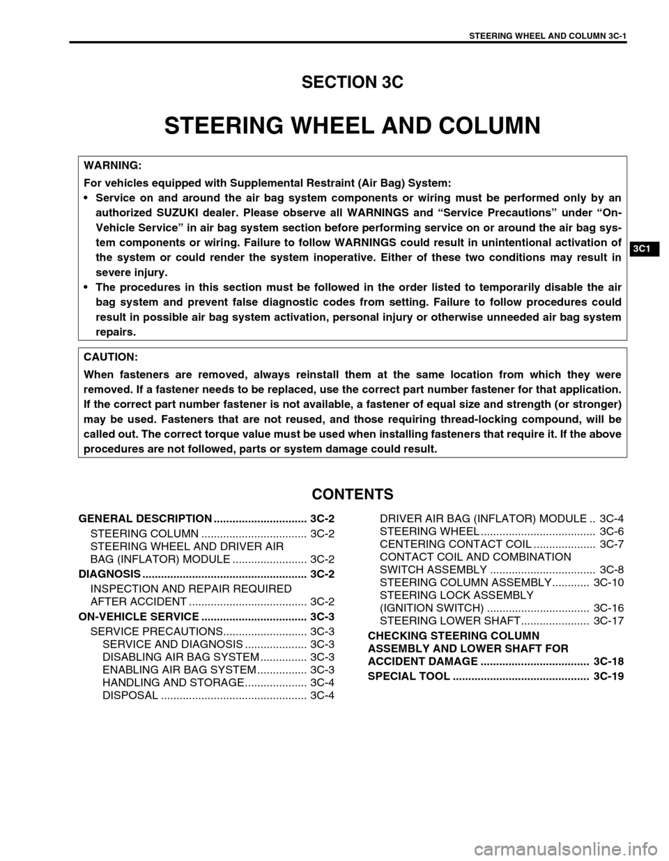
STEERING WHEEL AND COLUMN 3C-1
6F1
6F2
6G
6H
6K
7A
7A1
7B1
3C1
7E
7F
8A
8B
8C
8D
8E
9
10
10A
10B
SECTION 3C
STEERING WHEEL AND COLUMN
CONTENTS
GENERAL DESCRIPTION .............................. 3C-2
STEERING COLUMN .................................. 3C-2
STEERING WHEEL AND DRIVER AIR
BAG (INFLATOR) MODULE ........................ 3C-2
DIAGNOSIS ..................................................... 3C-2
INSPECTION AND REPAIR REQUIRED
AFTER ACCIDENT ...................................... 3C-2
ON-VEHICLE SERVICE .................................. 3C-3
SERVICE PRECAUTIONS........................... 3C-3
SERVICE AND DIAGNOSIS .................... 3C-3
DISABLING AIR BAG SYSTEM ............... 3C-3
ENABLING AIR BAG SYSTEM ................ 3C-3
HANDLING AND STORAGE.................... 3C-4
DISPOSAL ............................................... 3C-4DRIVER AIR BAG (INFLATOR) MODULE .. 3C-4
STEERING WHEEL ..................................... 3C-6
CENTERING CONTACT COIL .................... 3C-7
CONTACT COIL AND COMBINATION
SWITCH ASSEMBLY .................................. 3C-8
STEERING COLUMN ASSEMBLY............ 3C-10
STEERING LOCK ASSEMBLY
(IGNITION SWITCH) ................................. 3C-16
STEERING LOWER SHAFT...................... 3C-17
CHECKING STEERING COLUMN
ASSEMBLY AND LOWER SHAFT FOR
ACCIDENT DAMAGE ................................... 3C-18
SPECIAL TOOL ............................................ 3C-19
WARNING:
For vehicles equipped with Supplemental Restraint (Air Bag) System:
Service on and around the air bag system components or wiring must be performed only by an
authorized SUZUKI dealer. Please observe all WARNINGS and “Service Precautions” under “On-
Vehicle Service” in air bag system section before performing service on or around the air bag sys-
tem components or wiring. Failure to follow WARNINGS could result in unintentional activation of
the system or could render the system inoperative. Either of these two conditions may result in
severe injury.
The procedures in this section must be followed in the order listed to temporarily disable the air
bag system and prevent false diagnostic codes from setting. Failure to follow procedures could
result in possible air bag system activation, personal injury or otherwise unneeded air bag system
repairs.
CAUTION:
When fasteners are removed, always reinstall them at the same location from which they were
removed. If a fastener needs to be replaced, use the correct part number fastener for that application.
If the correct part number fastener is not available, a fastener of equal size and strength (or stronger)
may be used. Fasteners that are not reused, and those requiring thread-locking compound, will be
called out. The correct torque value must be used when installing fasteners that require it. If the above
procedures are not followed, parts or system damage could result.