air condition SUZUKI SWIFT 2000 1.G RG413 Service User Guide
[x] Cancel search | Manufacturer: SUZUKI, Model Year: 2000, Model line: SWIFT, Model: SUZUKI SWIFT 2000 1.GPages: 698, PDF Size: 16.01 MB
Page 48 of 698
MAINTENANCE AND LUBRICATION 0B-19
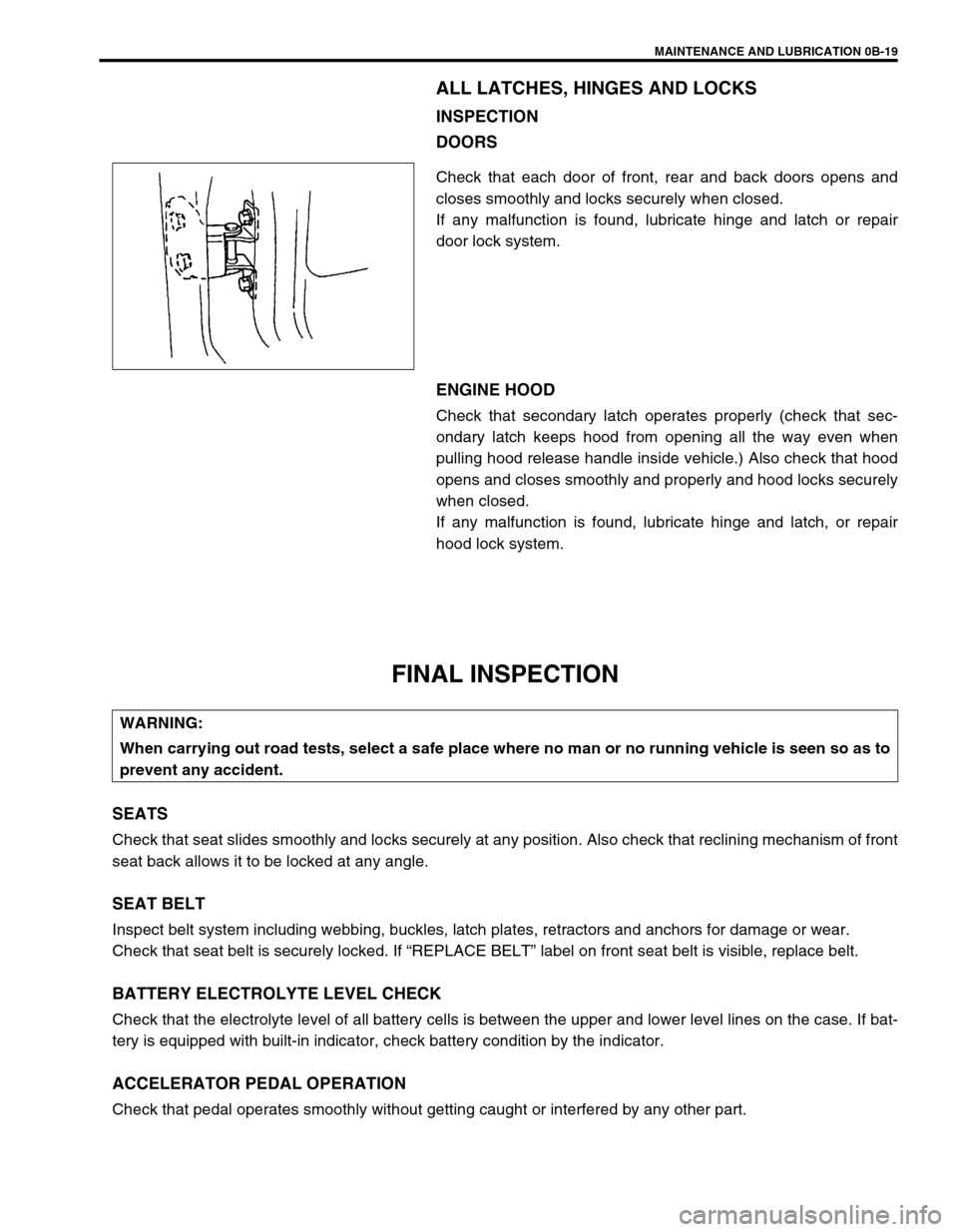
ALL LATCHES, HINGES AND LOCKS
INSPECTION
DOORS
Check that each door of front, rear and back doors opens and
closes smoothly and locks securely when closed.
If any malfunction is found, lubricate hinge and latch or repair
door lock system.
ENGINE HOOD
Check that secondary latch operates properly (check that sec-
ondary latch keeps hood from opening all the way even when
pulling hood release handle inside vehicle.) Also check that hood
opens and closes smoothly and properly and hood locks securely
when closed.
If any malfunction is found, lubricate hinge and latch, or repair
hood lock system.
FINAL INSPECTION
SEATS
Check that seat slides smoothly and locks securely at any position. Also check that reclining mechanism of front
seat back allows it to be locked at any angle.
SEAT BELT
Inspect belt system including webbing, buckles, latch plates, retractors and anchors for damage or wear.
Check that seat belt is securely locked. If “REPLACE BELT” label on front seat belt is visible, replace belt.
BATTERY ELECTROLYTE LEVEL CHECK
Check that the electrolyte level of all battery cells is between the upper and lower level lines on the case. If bat-
tery is equipped with built-in indicator, check battery condition by the indicator.
ACCELERATOR PEDAL OPERATION
Check that pedal operates smoothly without getting caught or interfered by any other part.
WARNING:
When carrying out road tests, select a safe place where no man or no running vehicle is seen so as to
prevent any accident.
Page 49 of 698
0B-20 MAINTENANCE AND LUBRICATION
ENGINE START
Check engine start for readiness.
On automatic transmission vehicles, try to start the engine in each select lever position. The starting motor
should crank only in “P” (Park) or “N” (Neutral).
On manual transmission vehicles, place the shift lever in “Neutral,” depress clutch pedal fully any try to start.
EXHAUST SYSTEM CHECK
Check for leakage, cracks or loose supports.
CLUTCH (FOR MANUAL TRANSMISSION)
Check for the following.
Clutch is completely released when depressing clutch pedal,
No slipping clutch occurs when releasing pedal and accelerating.
Clutch itself is free from any abnormal condition.
GEARSHIFT OR SELECT LEVER (TRANSMISSION)
Check gear shift or select lever for smooth shifting to all positions and for good performance of transmission in
any position.
With automatic transmission equipped vehicle, also check that shift indicator indicates properly according to
which position select lever is shifted to.
With automatic transmission equipped vehicle, make sure that vehicle is at complete stop when shifting select
lever to “P” range position and release all brakes.
BRAKE
Foot Brake
Check the followings:
that brake pedal has proper travel,
that brake works properly,
that it is free from noise,
that vehicle does not pull to one side when brake is applied.
and that brake do not drag.
Parking Brake
Check that lever has proper travel.
Check to ensure that parking brake is fully effective when the vehicle is stopped on the safe slope and brake
lever is pulled all the way.WARNING:
Before performing the following check, be sure to have enough room around the vehicle. Then, firmly
apply both the parking brake and the regular brakes. Do not use the accelerator pedal. If the engine
starts, be ready to turn off the ignition promptly. Take these precautions because the vehicle could
move without warning and possibly cause personal injury or property damage.
WARNING:
With vehicle parked on a fairly steep slope, make sure nothing is in the way downhill to avoid any per-
sonal injury or property damage. Be prepared to apply regular brake quickly even if vehicle should
start to move.
Page 50 of 698
MAINTENANCE AND LUBRICATION 0B-21
STEERING
Check to ensure that steering wheel is free from instability, or abnormally heavy feeling.
Check that the vehicle does not wander or pull to one side.
ENGINE
Check that engine responds readily at all speeds.
Check that engine is free from abnormal noise and abnormal vibration.
BODY, WHEELS AND POWER TRANSMITTING SYSTEM
Check that body, wheels and power transmitting system are free from abnormal noise and abnormal vibration or
any other abnormal condition.
METERS AND GAUGE
Check that speedometer, odometer, fuel meter, temperature gauge, etc. are operating accurately.
LIGHTS
Check that all lights operate properly.
WINDSHIELD DEFROSTER
Periodically check that air comes out from defroster outlet when operating heater or air conditioning.
Set mode control lever to defroster position and fan switch lever to “HI” position for this check.
RECOMMENDED FLUIDS AND LUBRICANTS
Engine oil SE, SF, SG, SH or SJ grade (Refer to “ENGINE OIL AND OIL FILTER”
in this section for engine oil viscosity.)
Engine coolant
(Ethylene glycol base coolant)“Antifreeze/Anticorrosion coolant”
Brake fluid DOT 3
Manual transmission oil Refer to “M/T OIL CHANGE” in Section 7A.
Transfer oil (4WD) Refer to “TRANSFER OIL CHANGE” in Section 7D.
Differential oil (4WD) Refer to “DIFFERENTIAL OIL CHANGE” in Section 7F.
Automatic transmission fluid
An equivalent of DEXRON
®-III
Door hinges Engine oil or water resistance chassis grease
Hood latch assembly Engine oil or water resistance chassis grease
Key lock cylinder Spray lubricant
Page 52 of 698
HEATER AND VENTILATION 1A-1
6F1
6F2
6G
1A
6K
7A
7A1
7B1
7C1
7D
7E
7F
8A
8B
8C
8D
8E
9
10
10A
10B
SECTION 1A
HEATER AND VENTILATION
CONTENTS
GENERAL DESCRIPTION .............................. 1A-2
DIAGNOSIS ..................................................... 1A-3
DIAGNOSIS TABLE ..................................... 1A-3
WIRING CIRCUIT ........................................ 1A-4
ON-VEHICLE SERVICE .................................. 1A-5
HEATER UNIT ............................................. 1A-5BLOWER FAN MOTOR ............................... 1A-7
BLOWER FAN MOTOR RESISTOR ........... 1A-8
HEATER CONTROL ASSEMBLY ............... 1A-9
AIR INLET BOX ......................................... 1A-12
VENTILATION LOUVER............................ 1A-13
REQUIRED SERVICE MATERIALS ............. 1A-14
WARNING:
For vehicles equipped with Supplement Restraint (Air Bag) System
Service on and around the air bag system components or wiring must be performed only by an
authorized SUZUKI dealer. Refer to “Air Bag System Components and Wiring Location View” under
“General Description” in Section 10B in order to confirm whether you are performing service on or
near the air bag system components or wiring. Please observe all WARNINGS and “Service Precau-
tions” under “On-Vehicle Service” in Section 10B before performing service on or around the air
bag system components or wiring. Failure to follow WARNINGS could result in unintentional activa-
tion of the system or could render the system inoperative. Either or these two conditions may result
in severe injury.
Technical service work must be started at least 90 seconds after the ignition switch is turned to the
“LOCK” position and the negative cable is disconnected from the battery. Otherwise, the system
may be activated by reserve energy in the Sensing and Diagnostic Module (SDM).
NOTE:
The link mechanism of the heater varies depending on the specifications.
Page 54 of 698
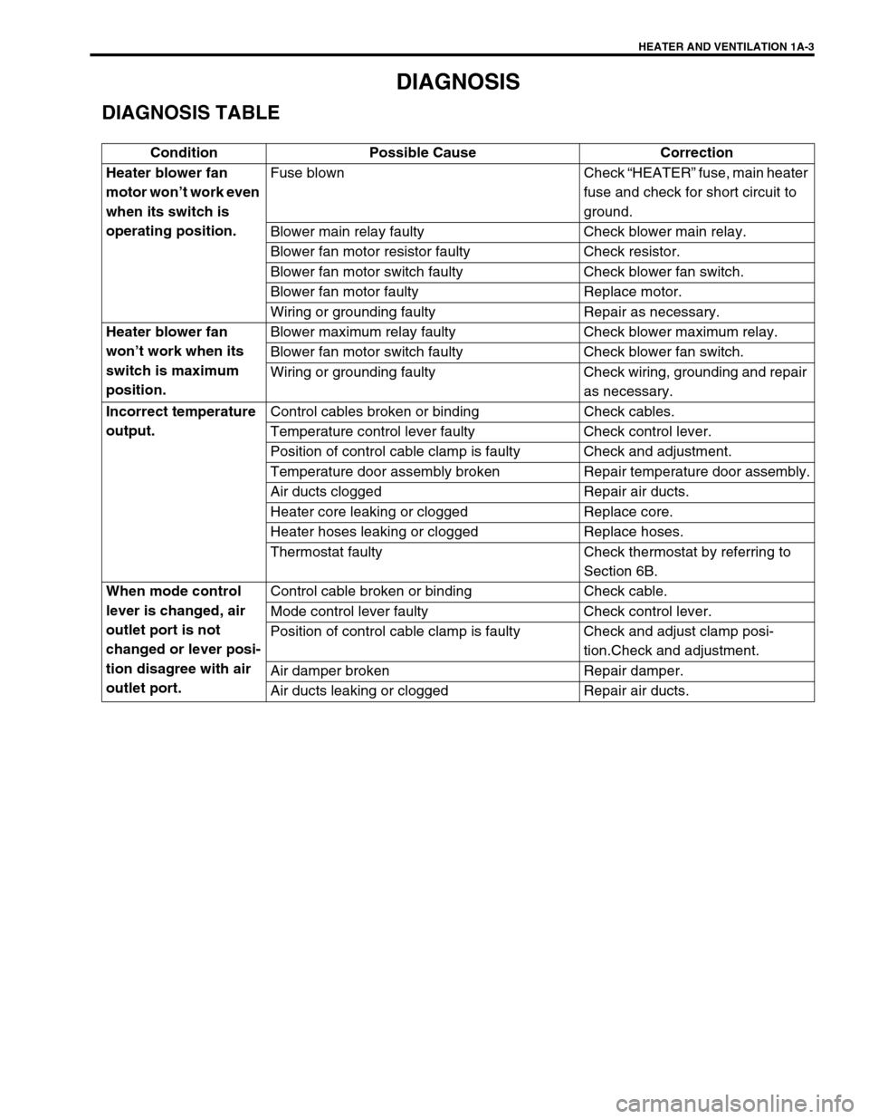
HEATER AND VENTILATION 1A-3
DIAGNOSIS
DIAGNOSIS TABLE
Condition Possible Cause Correction
Heater blower fan
motor won’t work even
when its switch is
operating position.Fuse blown Check “HEATER” fuse, main heater
fuse and check for short circuit to
ground.
Blower main relay faulty Check blower main relay.
Blower fan motor resistor faulty Check resistor.
Blower fan motor switch faulty Check blower fan switch.
Blower fan motor faulty Replace motor.
Wiring or grounding faulty Repair as necessary.
Heater blower fan
won’t work when its
switch is maximum
position.Blower maximum relay faulty Check blower maximum relay.
Blower fan motor switch faulty Check blower fan switch.
Wiring or grounding faulty Check wiring, grounding and repair
as necessary.
Incorrect temperature
output.Control cables broken or binding Check cables.
Temperature control lever faulty Check control lever.
Position of control cable clamp is faulty Check and adjustment.
Temperature door assembly broken Repair temperature door assembly.
Air ducts clogged Repair air ducts.
Heater core leaking or clogged Replace core.
Heater hoses leaking or clogged Replace hoses.
Thermostat faulty Check thermostat by referring to
Section 6B.
When mode control
lever is changed, air
outlet port is not
changed or lever posi-
tion disagree with air
outlet port.Control cable broken or binding Check cable.
Mode control lever faulty Check control lever.
Position of control cable clamp is faulty Check and adjust clamp posi-
tion.Check and adjustment.
Air damper broken Repair damper.
Air ducts leaking or clogged Repair air ducts.
Page 66 of 698
AIR CONDITIONING (OPTIONAL) 1B-1
6F1
6F2
6G
1B
7A
7A1
7B1
7C1
7D
7E
7F
8A
8B
8C
8D
8E
9
10
10A
10B
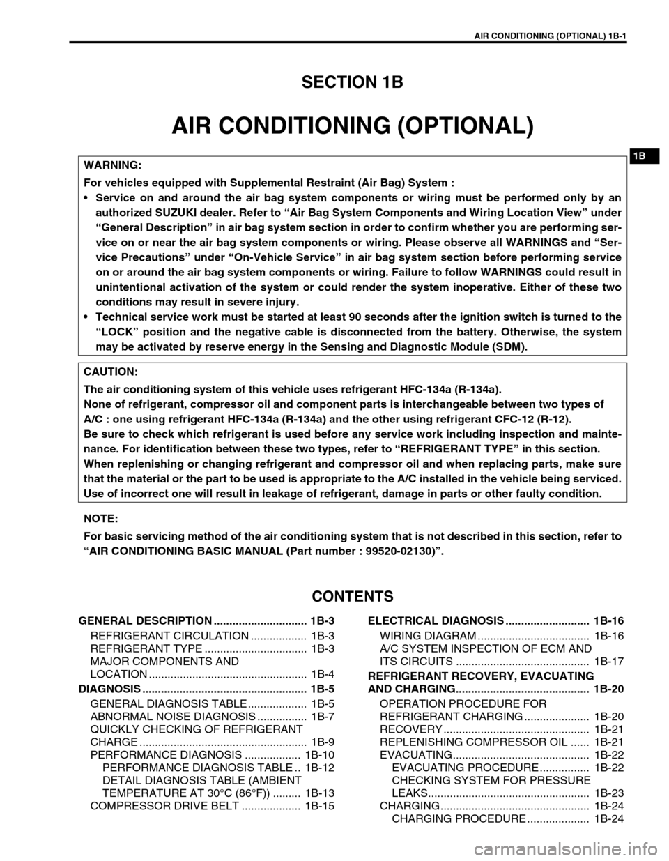
SECTION 1B
AIR CONDITIONING (OPTIONAL)
CONTENTS
GENERAL DESCRIPTION .............................. 1B-3
REFRIGERANT CIRCULATION .................. 1B-3
REFRIGERANT TYPE ................................. 1B-3
MAJOR COMPONENTS AND
LOCATION ................................................... 1B-4
DIAGNOSIS ..................................................... 1B-5
GENERAL DIAGNOSIS TABLE ................... 1B-5
ABNORMAL NOISE DIAGNOSIS ................ 1B-7
QUICKLY CHECKING OF REFRIGERANT
CHARGE ...................................................... 1B-9
PERFORMANCE DIAGNOSIS .................. 1B-10
PERFORMANCE DIAGNOSIS TABLE .. 1B-12
DETAIL DIAGNOSIS TABLE (AMBIENT
TEMPERATURE AT 30°C (86°F)) ......... 1B-13
COMPRESSOR DRIVE BELT ................... 1B-15ELECTRICAL DIAGNOSIS ........................... 1B-16
WIRING DIAGRAM .................................... 1B-16
A/C SYSTEM INSPECTION OF ECM AND
ITS CIRCUITS ........................................... 1B-17
REFRIGERANT RECOVERY, EVACUATING
AND CHARGING........................................... 1B-20
OPERATION PROCEDURE FOR
REFRIGERANT CHARGING ..................... 1B-20
RECOVERY ............................................... 1B-21
REPLENISHING COMPRESSOR OIL ...... 1B-21
EVACUATING............................................ 1B-22
EVACUATING PROCEDURE ................ 1B-22
CHECKING SYSTEM FOR PRESSURE
LEAKS.................................................... 1B-23
CHARGING................................................ 1B-24
CHARGING PROCEDURE .................... 1B-24 WARNING:
For vehicles equipped with Supplemental Restraint (Air Bag) System :
Service on and around the air bag system components or wiring must be performed only by an
authorized SUZUKI dealer. Refer to “Air Bag System Components and Wiring Location View” under
“General Description” in air bag system section in order to confirm whether you are performing ser-
vice on or near the air bag system components or wiring. Please observe all WARNINGS and “Ser-
vice Precautions” under “On-Vehicle Service” in air bag system section before performing service
on or around the air bag system components or wiring. Failure to follow WARNINGS could result in
unintentional activation of the system or could render the system inoperative. Either of these two
conditions may result in severe injury.
Technical service work must be started at least 90 seconds after the ignition switch is turned to the
“LOCK” position and the negative cable is disconnected from the battery. Otherwise, the system
may be activated by reserve energy in the Sensing and Diagnostic Module (SDM).
CAUTION:
The air conditioning system of this vehicle uses refrigerant HFC-134a (R-134a).
None of refrigerant, compressor oil and component parts is interchangeable between two types of
A/C : one using refrigerant HFC-134a (R-134a) and the other using refrigerant CFC-12 (R-12).
Be sure to check which refrigerant is used before any service work including inspection and mainte-
nance. For identification between these two types, refer to “REFRIGERANT TYPE” in this section.
When replenishing or changing refrigerant and compressor oil and when replacing parts, make sure
that the material or the part to be used is appropriate to the A/C installed in the vehicle being serviced.
Use of incorrect one will result in leakage of refrigerant, damage in parts or other faulty condition.
NOTE:
For basic servicing method of the air conditioning system that is not described in this section, refer to
“AIR CONDITIONING BASIC MANUAL (Part number : 99520-02130)”.
Page 67 of 698
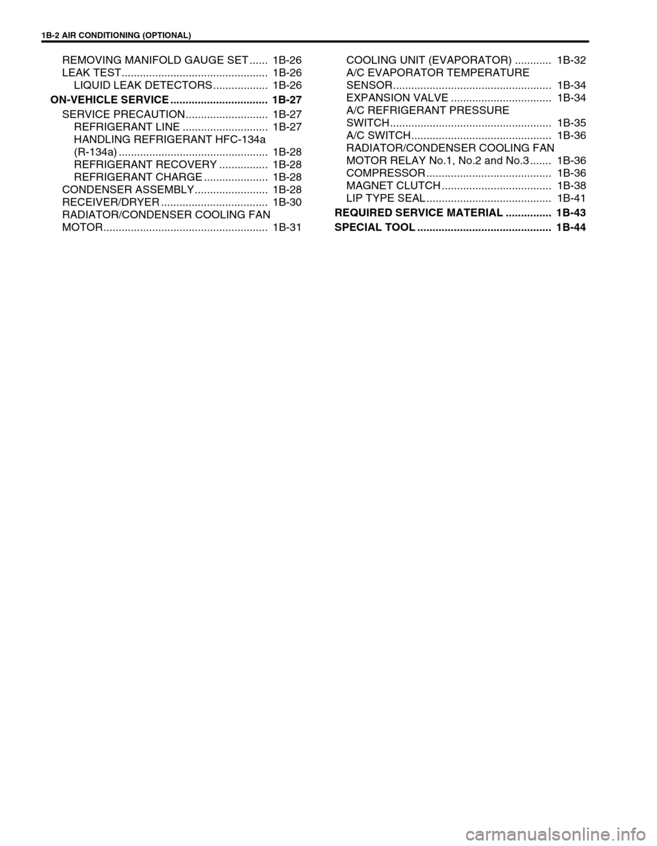
1B-2 AIR CONDITIONING (OPTIONAL)
REMOVING MANIFOLD GAUGE SET ...... 1B-26
LEAK TEST................................................ 1B-26
LIQUID LEAK DETECTORS .................. 1B-26
ON-VEHICLE SERVICE ................................ 1B-27
SERVICE PRECAUTION........................... 1B-27
REFRIGERANT LINE ............................ 1B-27
HANDLING REFRIGERANT HFC-134a
(R-134a) ................................................. 1B-28
REFRIGERANT RECOVERY ................ 1B-28
REFRIGERANT CHARGE ..................... 1B-28
CONDENSER ASSEMBLY........................ 1B-28
RECEIVER/DRYER ................................... 1B-30
RADIATOR/CONDENSER COOLING FAN
MOTOR...................................................... 1B-31COOLING UNIT (EVAPORATOR) ............ 1B-32
A/C EVAPORATOR TEMPERATURE
SENSOR.................................................... 1B-34
EXPANSION VALVE ................................. 1B-34
A/C REFRIGERANT PRESSURE
SWITCH..................................................... 1B-35
A/C SWITCH.............................................. 1B-36
RADIATOR/CONDENSER COOLING FAN
MOTOR RELAY No.1, No.2 and No.3 ....... 1B-36
COMPRESSOR ......................................... 1B-36
MAGNET CLUTCH .................................... 1B-38
LIP TYPE SEAL ......................................... 1B-41
REQUIRED SERVICE MATERIAL ............... 1B-43
SPECIAL TOOL ............................................ 1B-44
Page 68 of 698
AIR CONDITIONING (OPTIONAL) 1B-3
GENERAL DESCRIPTION
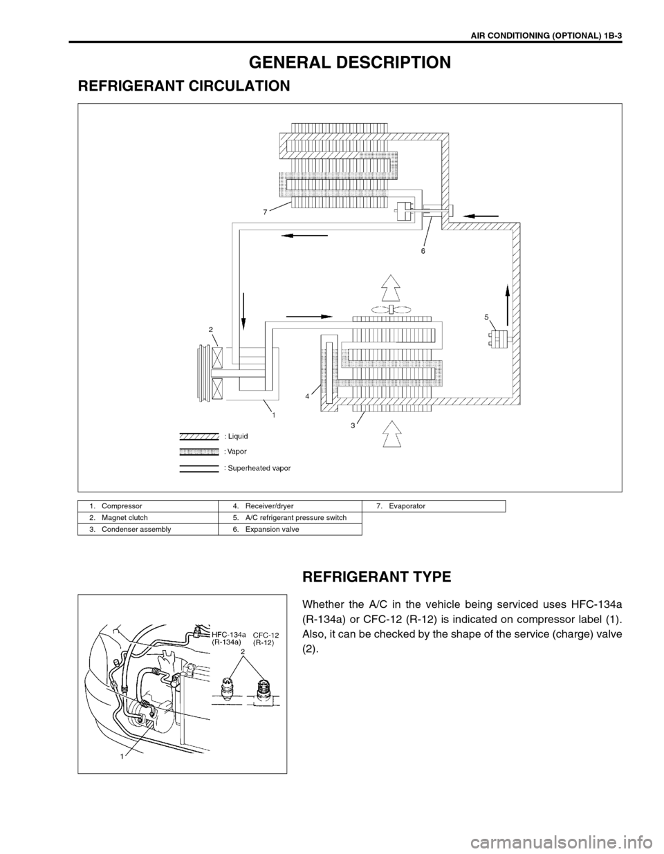
REFRIGERANT CIRCULATION
REFRIGERANT TYPE
Whether the A/C in the vehicle being serviced uses HFC-134a
(R-134a) or CFC-12 (R-12) is indicated on compressor label (1).
Also, it can be checked by the shape of the service (charge) valve
(2).
1. Compressor 4. Receiver/dryer 7. Evaporator
2. Magnet clutch 5. A/C refrigerant pressure switch
3. Condenser assembly 6. Expansion valve
Page 69 of 698

1B-4 AIR CONDITIONING (OPTIONAL)
MAJOR COMPONENTS AND LOCATION
1. Cooling unit 7. Condenser outlet pipe 13. Demister air 19. High pressure charge valve
2. Compressor 8. Liquid pipe 14. Fresh air 20. Sight glass
3. Condenser assembly 9. Expansion valve 15. Recirculation air [A] : LH model
4. Receiver/dryer 10. Ventilation air 16. Heater unit [B] : RH model
5. Discharge hose 11. Foot air 17. A/C refrigerant pressure switch
6. Suction pipe 12. Defroster air 18. Low pressure charge valve
Page 70 of 698
AIR CONDITIONING (OPTIONAL) 1B-5
DIAGNOSIS
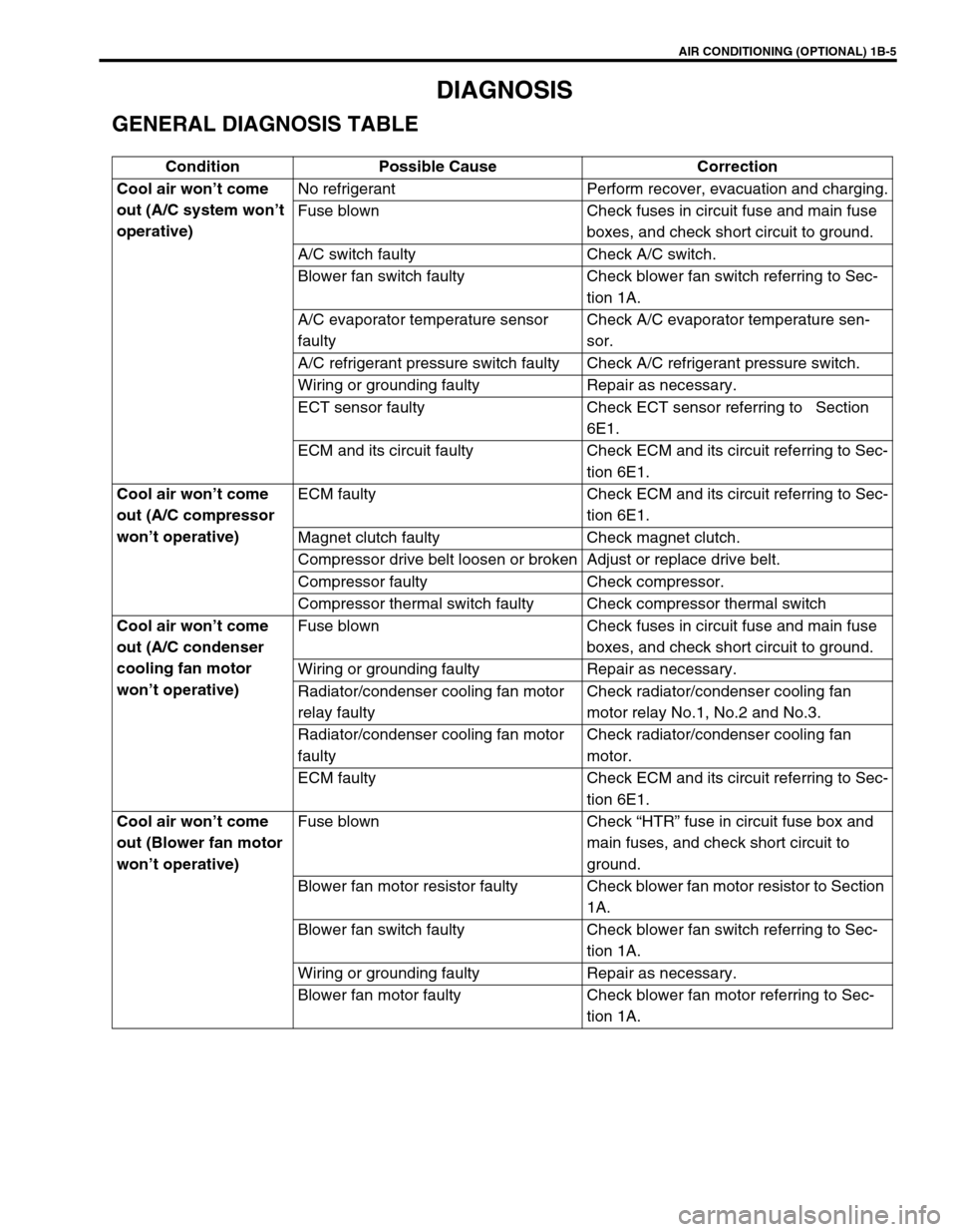
GENERAL DIAGNOSIS TABLE
Condition Possible Cause Correction
Cool air won’t come
out (A/C system won’t
operative)No refrigerant Perform recover, evacuation and charging.
Fuse blown Check fuses in circuit fuse and main fuse
boxes, and check short circuit to ground.
A/C switch faulty Check A/C switch.
Blower fan switch faulty Check blower fan switch referring to Sec-
tion 1A.
A/C evaporator temperature sensor
faultyCheck A/C evaporator temperature sen-
sor.
A/C refrigerant pressure switch faulty Check A/C refrigerant pressure switch.
Wiring or grounding faulty Repair as necessary.
ECT sensor faulty Check ECT sensor referring to Section
6E1.
ECM and its circuit faulty Check ECM and its circuit referring to Sec-
tion 6E1.
Cool air won’t come
out (A/C compressor
won’t operative)ECM faulty Check ECM and its circuit referring to Sec-
tion 6E1.
Magnet clutch faulty Check magnet clutch.
Compressor drive belt loosen or broken Adjust or replace drive belt.
Compressor faulty Check compressor.
Compressor thermal switch faulty Check compressor thermal switch
Cool air won’t come
out (A/C condenser
cooling fan motor
won’t operative)Fuse blown Check fuses in circuit fuse and main fuse
boxes, and check short circuit to ground.
Wiring or grounding faulty Repair as necessary.
Radiator/condenser cooling fan motor
relay faultyCheck radiator/condenser cooling fan
motor relay No.1, No.2 and No.3.
Radiator/condenser cooling fan motor
faultyCheck radiator/condenser cooling fan
motor.
ECM faulty Check ECM and its circuit referring to Sec-
tion 6E1.
Cool air won’t come
out (Blower fan motor
won’t operative)Fuse blown Check “HTR” fuse in circuit fuse box and
main fuses, and check short circuit to
ground.
Blower fan motor resistor faulty Check blower fan motor resistor to Section
1A.
Blower fan switch faulty Check blower fan switch referring to Sec-
tion 1A.
Wiring or grounding faulty Repair as necessary.
Blower fan motor faulty Check blower fan motor referring to Sec-
tion 1A.