engine SUZUKI SWIFT 2000 1.G RG413 Service User Guide
[x] Cancel search | Manufacturer: SUZUKI, Model Year: 2000, Model line: SWIFT, Model: SUZUKI SWIFT 2000 1.GPages: 698, PDF Size: 16.01 MB
Page 31 of 698
0B-2 MAINTENANCE AND LUBRICATION
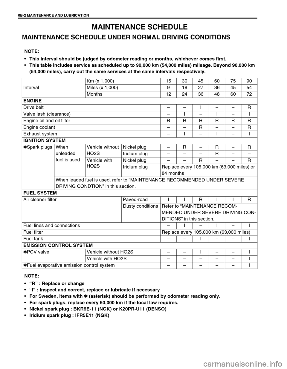
MAINTENANCE SCHEDULE
MAINTENANCE SCHEDULE UNDER NORMAL DRIVING CONDITIONS
NOTE:
This interval should be judged by odometer reading or months, whichever comes first.
This table includes service as scheduled up to 90,000 km (54,000 miles) mileage. Beyond 90,000 km
(54,000 miles), carry out the same services at the same intervals respectively.
IntervalKm (x 1,000) 15 30 45 60 75 90
Miles (x 1,000) 9 1827364554
Months 12 24 36 48 60 72
ENGINE
Drive belt––I––R
Valve lash (clearance) –I–I–I
Engine oil and oil filter R R R R R R
Engine coolant––R––R
Exhaust system–I–I–I
IGNITION SYSTEM
✱Spark plugs When
unleaded
fuel is usedVehicle without
HO2SNickel plug–R–R–R
Iridium plug–––R––
Vehicle with
HO2SNickel plug––R––R
Iridium plug Replace every 105,000 km (63,000 miles) or
84 months
When leaded fuel is used, refer to “MAINTENANCE RECOMMENDED UNDER SEVERE
DRIVING CONDTION” in this section.
FUEL SYSTEM
Air cleaner filter Paved-road I I R I I R
Dusty conditions Refer to “MAINTENANCE RECOM-
MENDED UNDER SEVERE DRIVING CON-
DITIONS” in this section.
Fuel lines and connections–I–I–I
Fuel filter Replace every 105,000 km (63,000 miles)
Fuel tank––I––I
EMISSION CONTROL SYSTEM
✱PCV valve Vehicle without HO2S––I––I
Vehicle with HO2S–––––I
✱Fuel evaporative emission control system–––––I
NOTE:
“R” : Replace or change
“I” : Inspect and correct, replace or lubricate if necessary
For Sweden, items with
✱
✱✱ ✱ (asterisk) should be performed by odometer reading only.
For spark plugs, replace every 50,000 km if the local law requires.
Nickel spark plug : BKR6E-11 (NGK) or K20PR-U11 (DENSO)
Iridium spark plug : IFR5E11 (NGK)
Page 33 of 698
0B-4 MAINTENANCE AND LUBRICATION
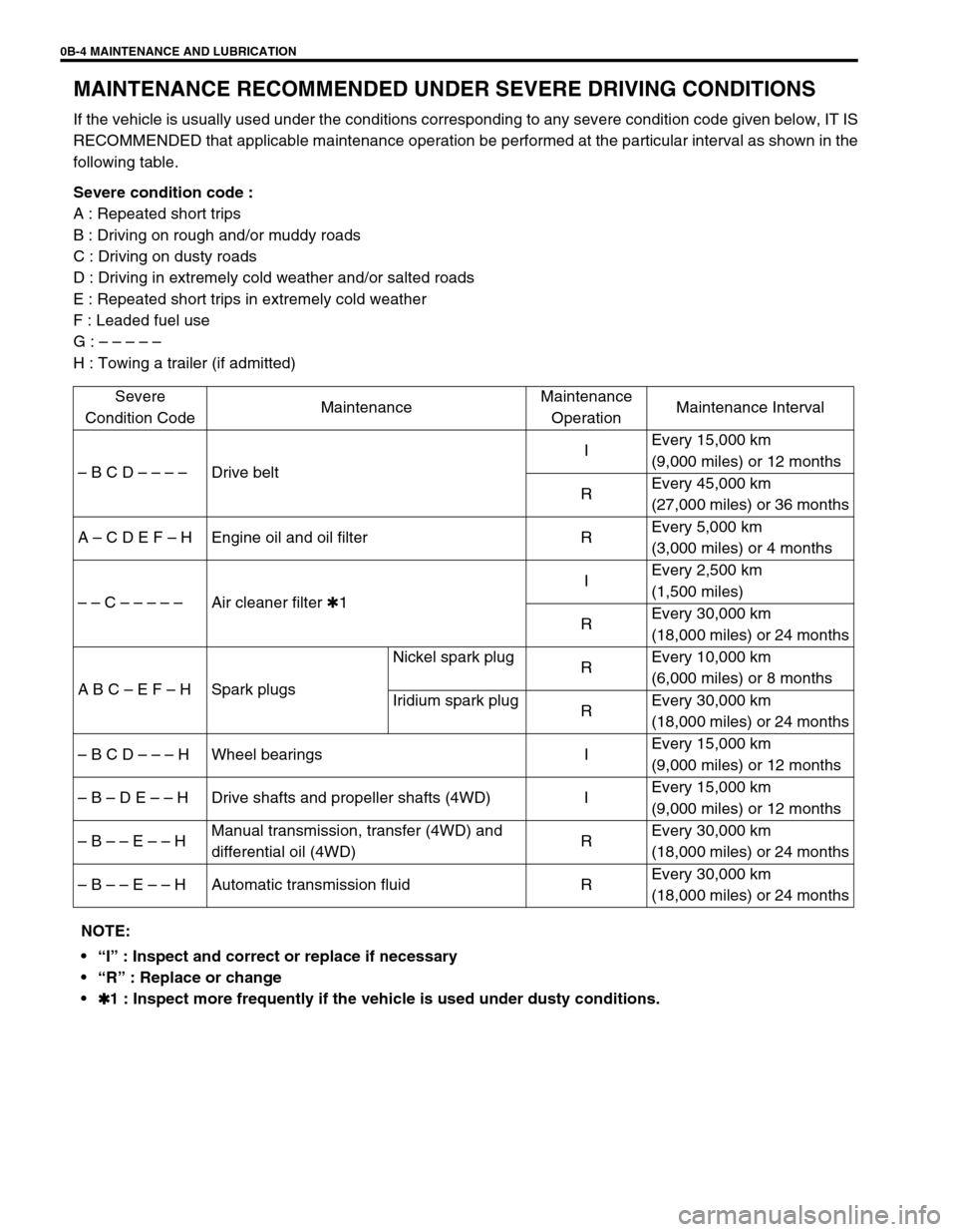
MAINTENANCE RECOMMENDED UNDER SEVERE DRIVING CONDITIONS
If the vehicle is usually used under the conditions corresponding to any severe condition code given below, IT IS
RECOMMENDED that applicable maintenance operation be performed at the particular interval as shown in the
following table.
Severe condition code :
A : Repeated short trips
B : Driving on rough and/or muddy roads
C : Driving on dusty roads
D : Driving in extremely cold weather and/or salted roads
E : Repeated short trips in extremely cold weather
F : Leaded fuel use
G : – – – – –
H : Towing a trailer (if admitted)
Severe
Condition CodeMaintenanceMaintenance
OperationMaintenance Interval
– B C D – – – –Drive beltIEvery 15,000 km
(9,000 miles) or 12 months
REvery 45,000 km
(27,000 miles) or 36 months
A – C D E F – H Engine oil and oil filter REvery 5,000 km
(3,000 miles) or 4 months
– – C – – – – –Air cleaner filter ✱1IEvery 2,500 km
(1,500 miles)
REvery 30,000 km
(18,000 miles) or 24 months
A B C – E F – H Spark plugsNickel spark plug
REvery 10,000 km
(6,000 miles) or 8 months
Iridium spark plug
REvery 30,000 km
(18,000 miles) or 24 months
– B C D – – – H Wheel bearings IEvery 15,000 km
(9,000 miles) or 12 months
– B – D E – – H Drive shafts and propeller shafts (4WD) IEvery 15,000 km
(9,000 miles) or 12 months
– B – – E – – HManual transmission, transfer (4WD) and
differential oil (4WD)REvery 30,000 km
(18,000 miles) or 24 months
– B – – E – – H Automatic transmission fluid REvery 30,000 km
(18,000 miles) or 24 months
NOTE:
“I” : Inspect and correct or replace if necessary
“R” : Replace or change
✱
✱✱ ✱1 : Inspect more frequently if the vehicle is used under dusty conditions.
Page 34 of 698
MAINTENANCE AND LUBRICATION 0B-5
MAINTENANCE SERVICE
ENGINE
DRIVE BELT
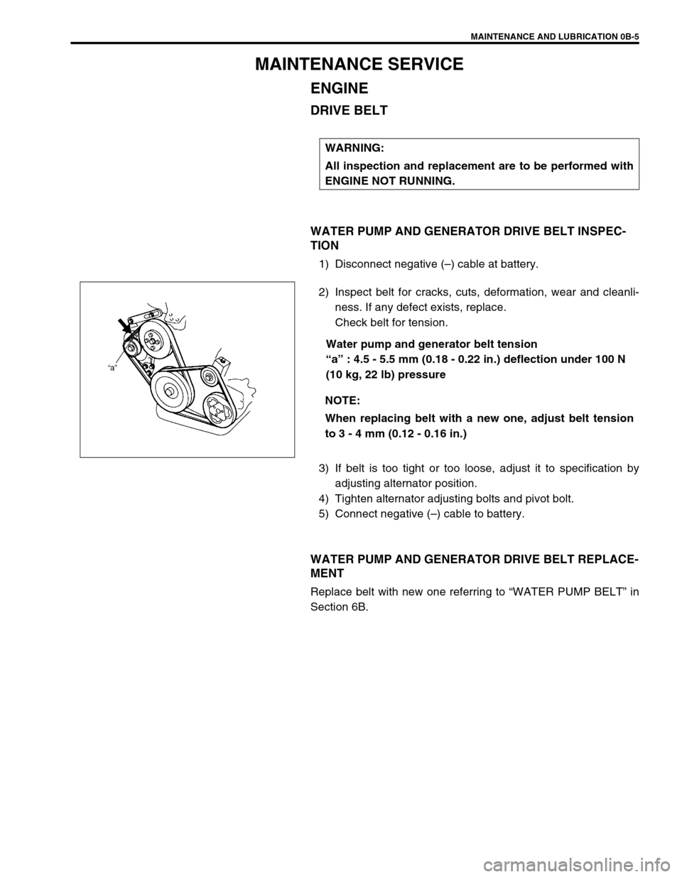
WATER PUMP AND GENERATOR DRIVE BELT INSPEC-
TION
1) Disconnect negative (–) cable at battery.
2) Inspect belt for cracks, cuts, deformation, wear and cleanli-
ness. If any defect exists, replace.
Check belt for tension.
Water pump and generator belt tension
“a” : 4.5 - 5.5 mm (0.18 - 0.22 in.) deflection under 100 N
(10 kg, 22 lb) pressure
3) If belt is too tight or too loose, adjust it to specification by
adjusting alternator position.
4) Tighten alternator adjusting bolts and pivot bolt.
5) Connect negative (–) cable to battery.
WATER PUMP AND GENERATOR DRIVE BELT REPLACE-
MENT
Replace belt with new one referring to “WATER PUMP BELT” in
Section 6B.WARNING:
All inspection and replacement are to be performed with
ENGINE NOT RUNNING.
NOTE:
When replacing belt with a new one, adjust belt tension
to 3 - 4 mm (0.12 - 0.16 in.)
Page 35 of 698
0B-6 MAINTENANCE AND LUBRICATION
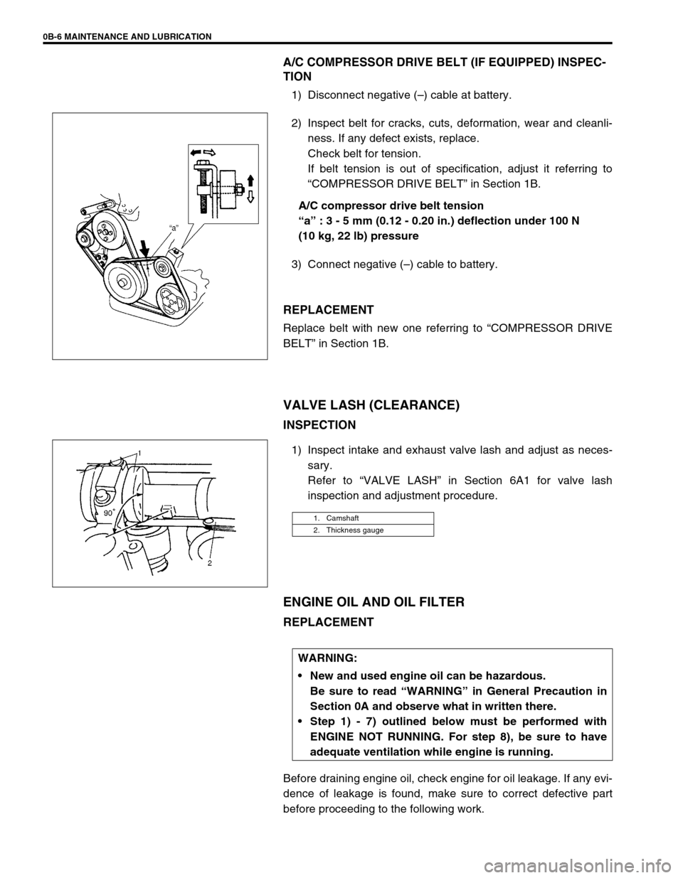
A/C COMPRESSOR DRIVE BELT (IF EQUIPPED) INSPEC-
TION
1) Disconnect negative (–) cable at battery.
2) Inspect belt for cracks, cuts, deformation, wear and cleanli-
ness. If any defect exists, replace.
Check belt for tension.
If belt tension is out of specification, adjust it referring to
“COMPRESSOR DRIVE BELT” in Section 1B.
A/C compressor drive belt tension
“a” : 3 - 5 mm (0.12 - 0.20 in.) deflection under 100 N
(10 kg, 22 lb) pressure
3) Connect negative (–) cable to battery.
REPLACEMENT
Replace belt with new one referring to “COMPRESSOR DRIVE
BELT” in Section 1B.
VALVE LASH (CLEARANCE)
INSPECTION
1) Inspect intake and exhaust valve lash and adjust as neces-
sary.
Refer to “VALVE LASH” in Section 6A1 for valve lash
inspection and adjustment procedure.
ENGINE OIL AND OIL FILTER
REPLACEMENT
Before draining engine oil, check engine for oil leakage. If any evi-
dence of leakage is found, make sure to correct defective part
before proceeding to the following work.
1. Camshaft
2. Thickness gauge
WARNING:
New and used engine oil can be hazardous.
Be sure to read “WARNING” in General Precaution in
Section 0A and observe what in written there.
Step 1) - 7) outlined below must be performed with
ENGINE NOT RUNNING. For step 8), be sure to have
adequate ventilation while engine is running.
Page 36 of 698
MAINTENANCE AND LUBRICATION 0B-7
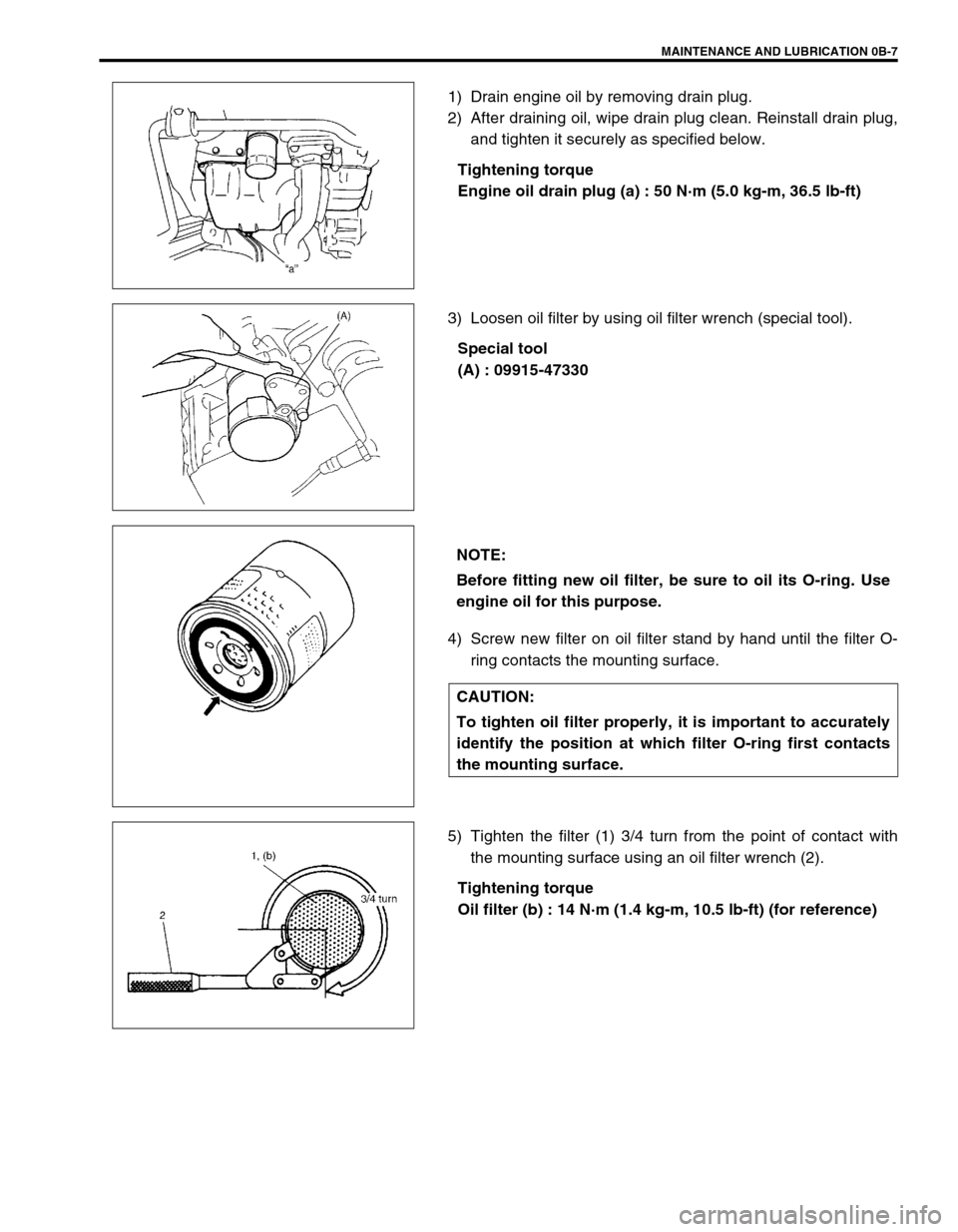
1) Drain engine oil by removing drain plug.
2) After draining oil, wipe drain plug clean. Reinstall drain plug,
and tighten it securely as specified below.
Tightening torque
Engine oil drain plug (a) : 50 N·m (5.0 kg-m, 36.5 lb-ft)
3) Loosen oil filter by using oil filter wrench (special tool).
Special tool
(A) : 09915-47330
4) Screw new filter on oil filter stand by hand until the filter O-
ring contacts the mounting surface.
5) Tighten the filter (1) 3/4 turn from the point of contact with
the mounting surface using an oil filter wrench (2).
Tightening torque
Oil filter (b) : 14 N·m (1.4 kg-m, 10.5 lb-ft) (for reference)
NOTE:
Before fitting new oil filter, be sure to oil its O-ring. Use
engine oil for this purpose.
CAUTION:
To tighten oil filter properly, it is important to accurately
identify the position at which filter O-ring first contacts
the mounting surface.
Page 37 of 698
0B-8 MAINTENANCE AND LUBRICATION
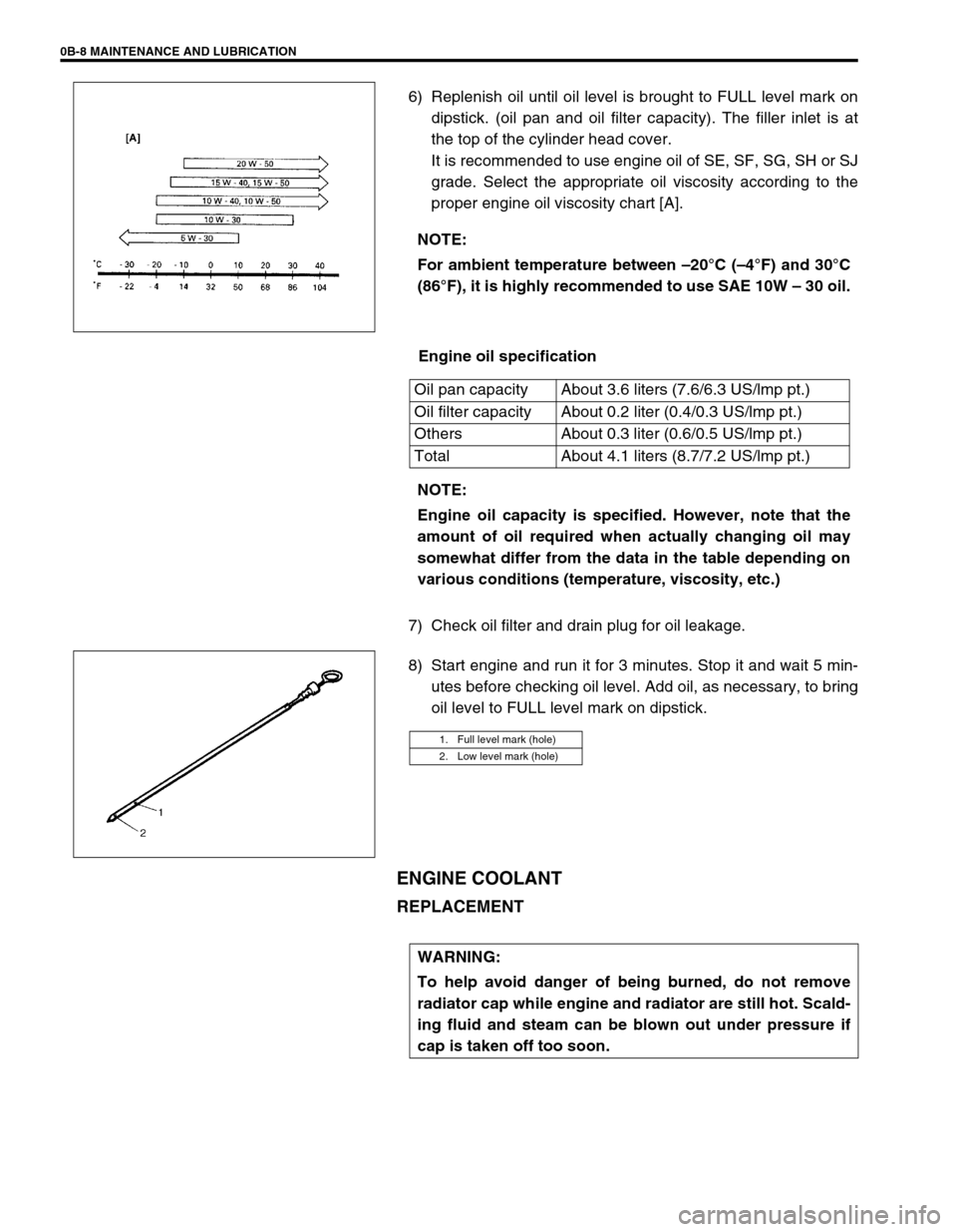
6) Replenish oil until oil level is brought to FULL level mark on
dipstick. (oil pan and oil filter capacity). The filler inlet is at
the top of the cylinder head cover.
It is recommended to use engine oil of SE, SF, SG, SH or SJ
grade. Select the appropriate oil viscosity according to the
proper engine oil viscosity chart [A].
Engine oil specification
7) Check oil filter and drain plug for oil leakage.
8) Start engine and run it for 3 minutes. Stop it and wait 5 min-
utes before checking oil level. Add oil, as necessary, to bring
oil level to FULL level mark on dipstick.
ENGINE COOLANT
REPLACEMENT
NOTE:
For ambient temperature between –20°C (–4°F) and 30°C
(86°F), it is highly recommended to use SAE 10W – 30 oil.
Oil pan capacity About 3.6 liters (7.6/6.3 US/lmp pt.)
Oil filter capacity About 0.2 liter (0.4/0.3 US/lmp pt.)
Others About 0.3 liter (0.6/0.5 US/lmp pt.)
Total About 4.1 liters (8.7/7.2 US/lmp pt.)
NOTE:
Engine oil capacity is specified. However, note that the
amount of oil required when actually changing oil may
somewhat differ from the data in the table depending on
various conditions (temperature, viscosity, etc.)
1. Full level mark (hole)
2. Low level mark (hole)
WARNING:
To help avoid danger of being burned, do not remove
radiator cap while engine and radiator are still hot. Scald-
ing fluid and steam can be blown out under pressure if
cap is taken off too soon.
Page 38 of 698
MAINTENANCE AND LUBRICATION 0B-9
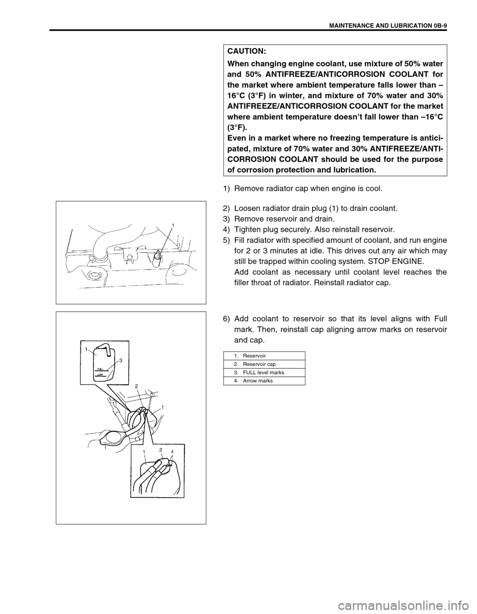
1) Remove radiator cap when engine is cool.
2) Loosen radiator drain plug (1) to drain coolant.
3) Remove reservoir and drain.
4) Tighten plug securely. Also reinstall reservoir.
5) Fill radiator with specified amount of coolant, and run engine
for 2 or 3 minutes at idle. This drives out any air which may
still be trapped within cooling system. STOP ENGINE.
Add coolant as necessary until coolant level reaches the
filler throat of radiator. Reinstall radiator cap.
6) Add coolant to reservoir so that its level aligns with Full
mark. Then, reinstall cap aligning arrow marks on reservoir
and cap. CAUTION:
When changing engine coolant, use mixture of 50% water
and 50% ANTIFREEZE/ANTICORROSION COOLANT for
the market where ambient temperature falls lower than –
16°C (3°F) in winter, and mixture of 70% water and 30%
ANTIFREEZE/ANTICORROSION COOLANT for the market
where ambient temperature doesn’t fall lower than –16°C
(3°F).
Even in a market where no freezing temperature is antici-
pated, mixture of 70% water and 30% ANTIFREEZE/ANTI-
CORROSION COOLANT should be used for the purpose
of corrosion protection and lubrication.
1. Reservoir
2. Reservoir cap
3. FULL level marks
4. Arrow marks
Page 45 of 698
0B-16 MAINTENANCE AND LUBRICATION
3) Check steering linkage for looseness and damage. Repair or
replace defective parts, if any.
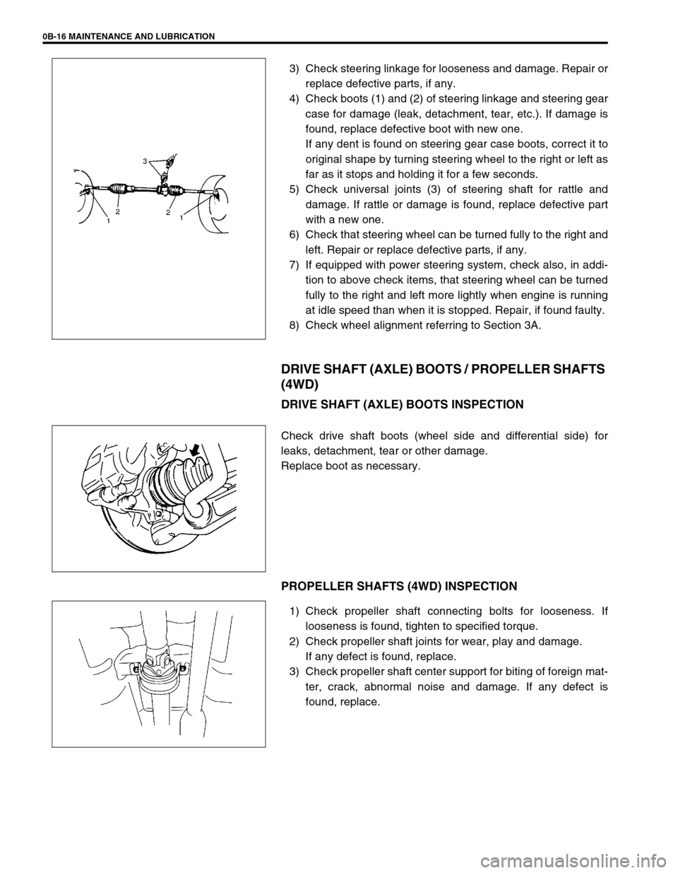
4) Check boots (1) and (2) of steering linkage and steering gear
case for damage (leak, detachment, tear, etc.). If damage is
found, replace defective boot with new one.
If any dent is found on steering gear case boots, correct it to
original shape by turning steering wheel to the right or left as
far as it stops and holding it for a few seconds.
5) Check universal joints (3) of steering shaft for rattle and
damage. If rattle or damage is found, replace defective part
with a new one.
6) Check that steering wheel can be turned fully to the right and
left. Repair or replace defective parts, if any.
7) If equipped with power steering system, check also, in addi-
tion to above check items, that steering wheel can be turned
fully to the right and left more lightly when engine is running
at idle speed than when it is stopped. Repair, if found faulty.
8) Check wheel alignment referring to Section 3A.
DRIVE SHAFT (AXLE) BOOTS / PROPELLER SHAFTS
(4WD)
DRIVE SHAFT (AXLE) BOOTS INSPECTION
Check drive shaft boots (wheel side and differential side) for
leaks, detachment, tear or other damage.
Replace boot as necessary.
PROPELLER SHAFTS (4WD) INSPECTION
1) Check propeller shaft connecting bolts for looseness. If
looseness is found, tighten to specified torque.
2) Check propeller shaft joints for wear, play and damage.
If any defect is found, replace.
3) Check propeller shaft center support for biting of foreign mat-
ter, crack, abnormal noise and damage. If any defect is
found, replace.
Page 48 of 698
MAINTENANCE AND LUBRICATION 0B-19
ALL LATCHES, HINGES AND LOCKS
INSPECTION
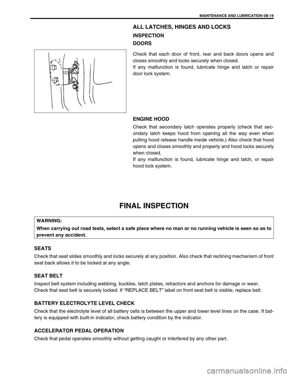
DOORS
Check that each door of front, rear and back doors opens and
closes smoothly and locks securely when closed.
If any malfunction is found, lubricate hinge and latch or repair
door lock system.
ENGINE HOOD
Check that secondary latch operates properly (check that sec-
ondary latch keeps hood from opening all the way even when
pulling hood release handle inside vehicle.) Also check that hood
opens and closes smoothly and properly and hood locks securely
when closed.
If any malfunction is found, lubricate hinge and latch, or repair
hood lock system.
FINAL INSPECTION
SEATS
Check that seat slides smoothly and locks securely at any position. Also check that reclining mechanism of front
seat back allows it to be locked at any angle.
SEAT BELT
Inspect belt system including webbing, buckles, latch plates, retractors and anchors for damage or wear.
Check that seat belt is securely locked. If “REPLACE BELT” label on front seat belt is visible, replace belt.
BATTERY ELECTROLYTE LEVEL CHECK
Check that the electrolyte level of all battery cells is between the upper and lower level lines on the case. If bat-
tery is equipped with built-in indicator, check battery condition by the indicator.
ACCELERATOR PEDAL OPERATION
Check that pedal operates smoothly without getting caught or interfered by any other part.
WARNING:
When carrying out road tests, select a safe place where no man or no running vehicle is seen so as to
prevent any accident.
Page 49 of 698
0B-20 MAINTENANCE AND LUBRICATION
ENGINE START
Check engine start for readiness.
On automatic transmission vehicles, try to start the engine in each select lever position. The starting motor
should crank only in “P” (Park) or “N” (Neutral).
On manual transmission vehicles, place the shift lever in “Neutral,” depress clutch pedal fully any try to start.
EXHAUST SYSTEM CHECK
Check for leakage, cracks or loose supports.
CLUTCH (FOR MANUAL TRANSMISSION)
Check for the following.
Clutch is completely released when depressing clutch pedal,
No slipping clutch occurs when releasing pedal and accelerating.
Clutch itself is free from any abnormal condition.
GEARSHIFT OR SELECT LEVER (TRANSMISSION)
Check gear shift or select lever for smooth shifting to all positions and for good performance of transmission in
any position.
With automatic transmission equipped vehicle, also check that shift indicator indicates properly according to
which position select lever is shifted to.
With automatic transmission equipped vehicle, make sure that vehicle is at complete stop when shifting select
lever to “P” range position and release all brakes.
BRAKE
Foot Brake
Check the followings:
that brake pedal has proper travel,
that brake works properly,
that it is free from noise,
that vehicle does not pull to one side when brake is applied.
and that brake do not drag.
Parking Brake
Check that lever has proper travel.
Check to ensure that parking brake is fully effective when the vehicle is stopped on the safe slope and brake
lever is pulled all the way.WARNING:
Before performing the following check, be sure to have enough room around the vehicle. Then, firmly
apply both the parking brake and the regular brakes. Do not use the accelerator pedal. If the engine
starts, be ready to turn off the ignition promptly. Take these precautions because the vehicle could
move without warning and possibly cause personal injury or property damage.
WARNING:
With vehicle parked on a fairly steep slope, make sure nothing is in the way downhill to avoid any per-
sonal injury or property damage. Be prepared to apply regular brake quickly even if vehicle should
start to move.