checking oil SUZUKI SWIFT 2000 1.G RG413 Service Workshop Manual
[x] Cancel search | Manufacturer: SUZUKI, Model Year: 2000, Model line: SWIFT, Model: SUZUKI SWIFT 2000 1.GPages: 698, PDF Size: 16.01 MB
Page 37 of 698
0B-8 MAINTENANCE AND LUBRICATION
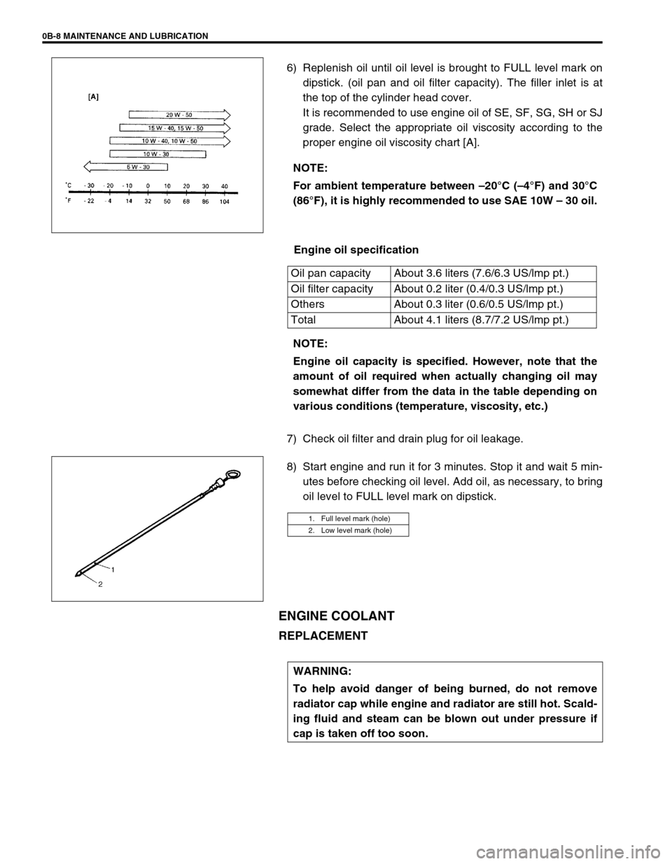
6) Replenish oil until oil level is brought to FULL level mark on
dipstick. (oil pan and oil filter capacity). The filler inlet is at
the top of the cylinder head cover.
It is recommended to use engine oil of SE, SF, SG, SH or SJ
grade. Select the appropriate oil viscosity according to the
proper engine oil viscosity chart [A].
Engine oil specification
7) Check oil filter and drain plug for oil leakage.
8) Start engine and run it for 3 minutes. Stop it and wait 5 min-
utes before checking oil level. Add oil, as necessary, to bring
oil level to FULL level mark on dipstick.
ENGINE COOLANT
REPLACEMENT
NOTE:
For ambient temperature between –20°C (–4°F) and 30°C
(86°F), it is highly recommended to use SAE 10W – 30 oil.
Oil pan capacity About 3.6 liters (7.6/6.3 US/lmp pt.)
Oil filter capacity About 0.2 liter (0.4/0.3 US/lmp pt.)
Others About 0.3 liter (0.6/0.5 US/lmp pt.)
Total About 4.1 liters (8.7/7.2 US/lmp pt.)
NOTE:
Engine oil capacity is specified. However, note that the
amount of oil required when actually changing oil may
somewhat differ from the data in the table depending on
various conditions (temperature, viscosity, etc.)
1. Full level mark (hole)
2. Low level mark (hole)
WARNING:
To help avoid danger of being burned, do not remove
radiator cap while engine and radiator are still hot. Scald-
ing fluid and steam can be blown out under pressure if
cap is taken off too soon.
Page 46 of 698
MAINTENANCE AND LUBRICATION 0B-17
MANUAL TRANSMISSION OIL
INSPECTION
1) Inspect transmission case for evidence of oil leakage.
Repair leaky point if any.
2) Make sure that vehicle is placed level for oil level check.
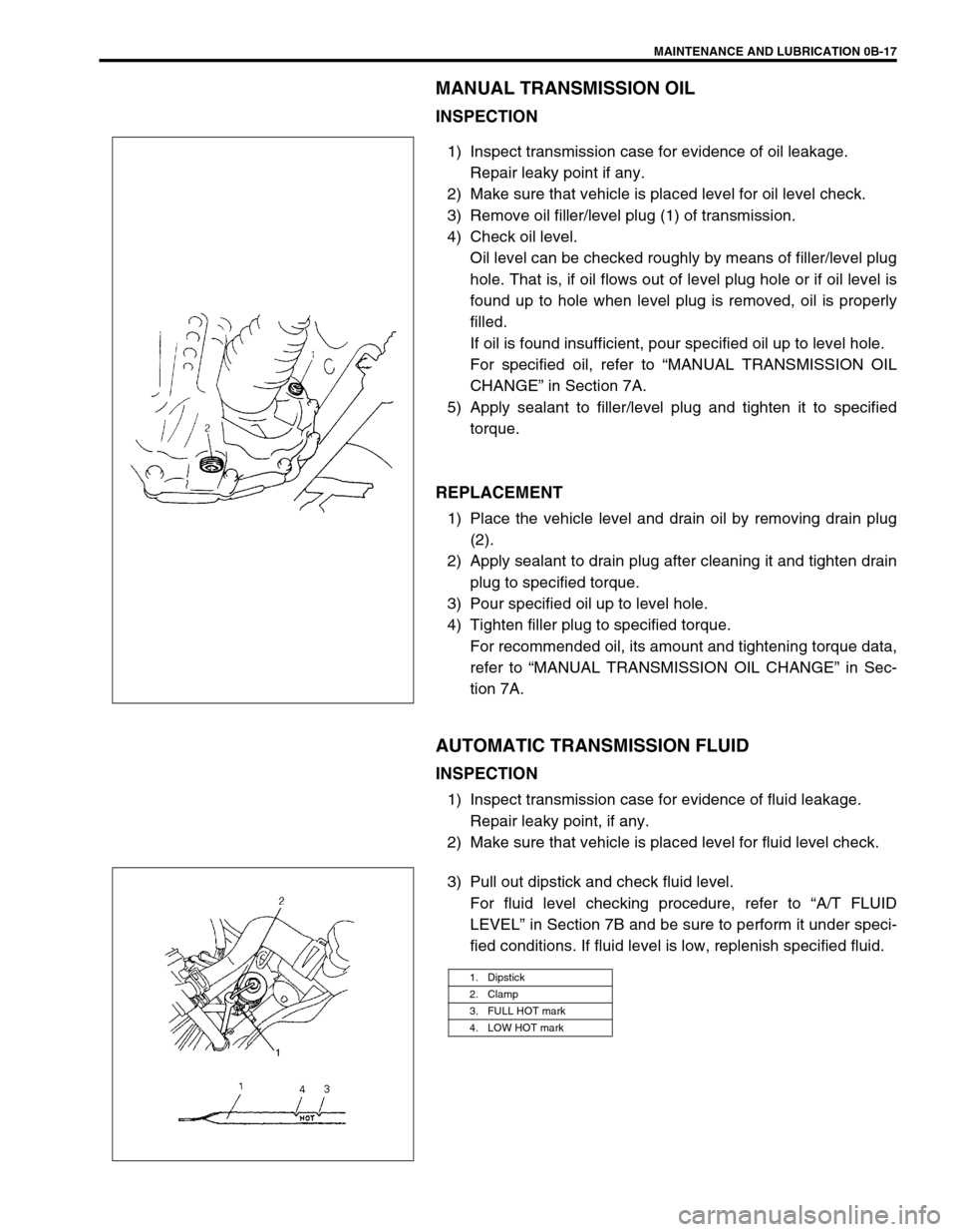
3) Remove oil filler/level plug (1) of transmission.
4) Check oil level.
Oil level can be checked roughly by means of filler/level plug
hole. That is, if oil flows out of level plug hole or if oil level is
found up to hole when level plug is removed, oil is properly
filled.
If oil is found insufficient, pour specified oil up to level hole.
For specified oil, refer to “MANUAL TRANSMISSION OIL
CHANGE” in Section 7A.
5) Apply sealant to filler/level plug and tighten it to specified
torque.
REPLACEMENT
1) Place the vehicle level and drain oil by removing drain plug
(2).
2) Apply sealant to drain plug after cleaning it and tighten drain
plug to specified torque.
3) Pour specified oil up to level hole.
4) Tighten filler plug to specified torque.
For recommended oil, its amount and tightening torque data,
refer to “MANUAL TRANSMISSION OIL CHANGE” in Sec-
tion 7A.
AUTOMATIC TRANSMISSION FLUID
INSPECTION
1) Inspect transmission case for evidence of fluid leakage.
Repair leaky point, if any.
2) Make sure that vehicle is placed level for fluid level check.
3) Pull out dipstick and check fluid level.
For fluid level checking procedure, refer to “A/T FLUID
LEVEL” in Section 7B and be sure to perform it under speci-
fied conditions. If fluid level is low, replenish specified fluid.
1. Dipstick
2. Clamp
3. FULL HOT mark
4. LOW HOT mark
Page 66 of 698
AIR CONDITIONING (OPTIONAL) 1B-1
6F1
6F2
6G
1B
7A
7A1
7B1
7C1
7D
7E
7F
8A
8B
8C
8D
8E
9
10
10A
10B
SECTION 1B
AIR CONDITIONING (OPTIONAL)
CONTENTS
GENERAL DESCRIPTION .............................. 1B-3
REFRIGERANT CIRCULATION .................. 1B-3
REFRIGERANT TYPE ................................. 1B-3
MAJOR COMPONENTS AND
LOCATION ................................................... 1B-4
DIAGNOSIS ..................................................... 1B-5
GENERAL DIAGNOSIS TABLE ................... 1B-5
ABNORMAL NOISE DIAGNOSIS ................ 1B-7
QUICKLY CHECKING OF REFRIGERANT
CHARGE ...................................................... 1B-9
PERFORMANCE DIAGNOSIS .................. 1B-10
PERFORMANCE DIAGNOSIS TABLE .. 1B-12
DETAIL DIAGNOSIS TABLE (AMBIENT
TEMPERATURE AT 30°C (86°F)) ......... 1B-13
COMPRESSOR DRIVE BELT ................... 1B-15ELECTRICAL DIAGNOSIS ........................... 1B-16
WIRING DIAGRAM .................................... 1B-16
A/C SYSTEM INSPECTION OF ECM AND
ITS CIRCUITS ........................................... 1B-17
REFRIGERANT RECOVERY, EVACUATING
AND CHARGING........................................... 1B-20
OPERATION PROCEDURE FOR
REFRIGERANT CHARGING ..................... 1B-20
RECOVERY ............................................... 1B-21
REPLENISHING COMPRESSOR OIL ...... 1B-21
EVACUATING............................................ 1B-22
EVACUATING PROCEDURE ................ 1B-22
CHECKING SYSTEM FOR PRESSURE
LEAKS.................................................... 1B-23
CHARGING................................................ 1B-24
CHARGING PROCEDURE .................... 1B-24 WARNING:
For vehicles equipped with Supplemental Restraint (Air Bag) System :
Service on and around the air bag system components or wiring must be performed only by an
authorized SUZUKI dealer. Refer to “Air Bag System Components and Wiring Location View” under
“General Description” in air bag system section in order to confirm whether you are performing ser-
vice on or near the air bag system components or wiring. Please observe all WARNINGS and “Ser-
vice Precautions” under “On-Vehicle Service” in air bag system section before performing service
on or around the air bag system components or wiring. Failure to follow WARNINGS could result in
unintentional activation of the system or could render the system inoperative. Either of these two
conditions may result in severe injury.
Technical service work must be started at least 90 seconds after the ignition switch is turned to the
“LOCK” position and the negative cable is disconnected from the battery. Otherwise, the system
may be activated by reserve energy in the Sensing and Diagnostic Module (SDM).
CAUTION:
The air conditioning system of this vehicle uses refrigerant HFC-134a (R-134a).
None of refrigerant, compressor oil and component parts is interchangeable between two types of
A/C : one using refrigerant HFC-134a (R-134a) and the other using refrigerant CFC-12 (R-12).
Be sure to check which refrigerant is used before any service work including inspection and mainte-
nance. For identification between these two types, refer to “REFRIGERANT TYPE” in this section.
When replenishing or changing refrigerant and compressor oil and when replacing parts, make sure
that the material or the part to be used is appropriate to the A/C installed in the vehicle being serviced.
Use of incorrect one will result in leakage of refrigerant, damage in parts or other faulty condition.
NOTE:
For basic servicing method of the air conditioning system that is not described in this section, refer to
“AIR CONDITIONING BASIC MANUAL (Part number : 99520-02130)”.
Page 141 of 698
3B-20 MANUAL RACK AND PINION
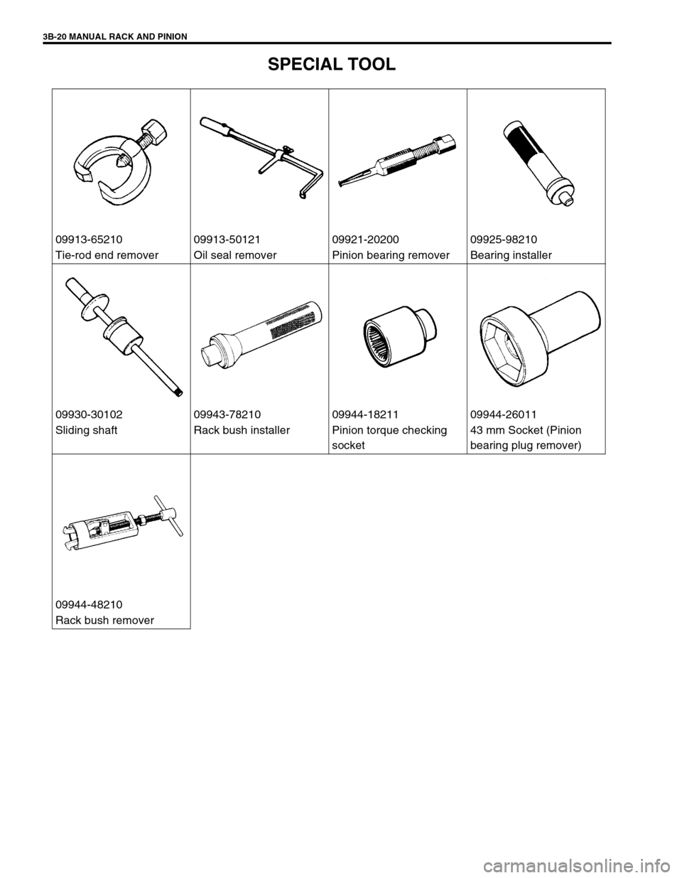
SPECIAL TOOL
09913-65210 09913-50121 09921-20200 09925-98210
Tie-rod end remover Oil seal remover Pinion bearing remover Bearing installer
09930-30102 09943-78210 09944-18211 09944-26011
Sliding shaft Rack bush installer Pinion torque checking
socket43 mm Socket (Pinion
bearing plug remover)
09944-48210
Rack bush remover
Page 174 of 698
STEERING WHEEL AND COLUMN 3C-1
6F1
6F2
6G
6H
6K
7A
7A1
7B1
3C1
7E
7F
8A
8B
8C
8D
8E
9
10
10A
10B
SECTION 3C
STEERING WHEEL AND COLUMN
CONTENTS
GENERAL DESCRIPTION .............................. 3C-2
STEERING COLUMN .................................. 3C-2
STEERING WHEEL AND DRIVER AIR
BAG (INFLATOR) MODULE ........................ 3C-2
DIAGNOSIS ..................................................... 3C-2
INSPECTION AND REPAIR REQUIRED
AFTER ACCIDENT ...................................... 3C-2
ON-VEHICLE SERVICE .................................. 3C-3
SERVICE PRECAUTIONS........................... 3C-3
SERVICE AND DIAGNOSIS .................... 3C-3
DISABLING AIR BAG SYSTEM ............... 3C-3
ENABLING AIR BAG SYSTEM ................ 3C-3
HANDLING AND STORAGE.................... 3C-4
DISPOSAL ............................................... 3C-4DRIVER AIR BAG (INFLATOR) MODULE .. 3C-4
STEERING WHEEL ..................................... 3C-6
CENTERING CONTACT COIL .................... 3C-7
CONTACT COIL AND COMBINATION
SWITCH ASSEMBLY .................................. 3C-8
STEERING COLUMN ASSEMBLY............ 3C-10
STEERING LOCK ASSEMBLY
(IGNITION SWITCH) ................................. 3C-16
STEERING LOWER SHAFT...................... 3C-17
CHECKING STEERING COLUMN
ASSEMBLY AND LOWER SHAFT FOR
ACCIDENT DAMAGE ................................... 3C-18
SPECIAL TOOL ............................................ 3C-19
WARNING:
For vehicles equipped with Supplemental Restraint (Air Bag) System:
Service on and around the air bag system components or wiring must be performed only by an
authorized SUZUKI dealer. Please observe all WARNINGS and “Service Precautions” under “On-
Vehicle Service” in air bag system section before performing service on or around the air bag sys-
tem components or wiring. Failure to follow WARNINGS could result in unintentional activation of
the system or could render the system inoperative. Either of these two conditions may result in
severe injury.
The procedures in this section must be followed in the order listed to temporarily disable the air
bag system and prevent false diagnostic codes from setting. Failure to follow procedures could
result in possible air bag system activation, personal injury or otherwise unneeded air bag system
repairs.
CAUTION:
When fasteners are removed, always reinstall them at the same location from which they were
removed. If a fastener needs to be replaced, use the correct part number fastener for that application.
If the correct part number fastener is not available, a fastener of equal size and strength (or stronger)
may be used. Fasteners that are not reused, and those requiring thread-locking compound, will be
called out. The correct torque value must be used when installing fasteners that require it. If the above
procedures are not followed, parts or system damage could result.
Page 396 of 698
ENGINE GENERAL INFORMATION AND DIAGNOSIS 6-27
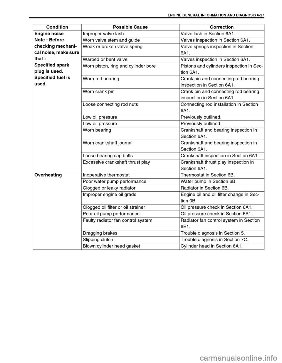
Engine noise
Note : Before
checking mechani-
cal noise, make sure
that :
Specified spark
plug is used.
Specified fuel is
used.Improper valve lash Valve lash in Section 6A1.
Worn valve stem and guide Valves inspection in Section 6A1.
Weak or broken valve spring Valve springs inspection in Section
6A1.
Warped or bent valve Valves inspection in Section 6A1.
Worn piston, ring and cylinder bore Pistons and cylinders inspection in Sec-
tion 6A1.
Worn rod bearing Crank pin and connecting rod bearing
inspection in Section 6A1.
Worn crank pin Crank pin and connecting rod bearing
inspection in Section 6A1.
Loose connecting rod nuts Connecting rod installation in Section
6A1.
Low oil pressure Previously outlined.
Low oil pressure Previously outlined.
Worn bearing Crankshaft and bearing inspection in
Section 6A1.
Worn crankshaft journal Crankshaft and bearing inspection in
Section 6A1.
Loose bearing cap bolts Crankshaft inspection in Section 6A1.
Excessive crankshaft thrust play Crankshaft thrust play inspection in
Section 6A1.
Overheating
Inoperative thermostat Thermostat in Section 6B.
Poor water pump performance Water pump in Section 6B.
Clogged or leaky radiator Radiator in Section 6B.
Improper engine oil grade Engine oil and oil filter change in Sec-
tion 0B.
Clogged oil filter or oil strainer Oil pressure check in Section 6A1.
Poor oil pump performance Oil pressure check in Section 6A1.
Faulty radiator fan control system Radiator fan control system in Section
6E1.
Dragging brakes Trouble diagnosis in Section 5.
Slipping clutch Trouble diagnosis in Section 7C.
Blown cylinder head gasket Cylinder head in Section 6A1. Condition Possible Cause Correction
Page 507 of 698
6A1-6 ENGINE MECHANICAL (M13 ENGINE)
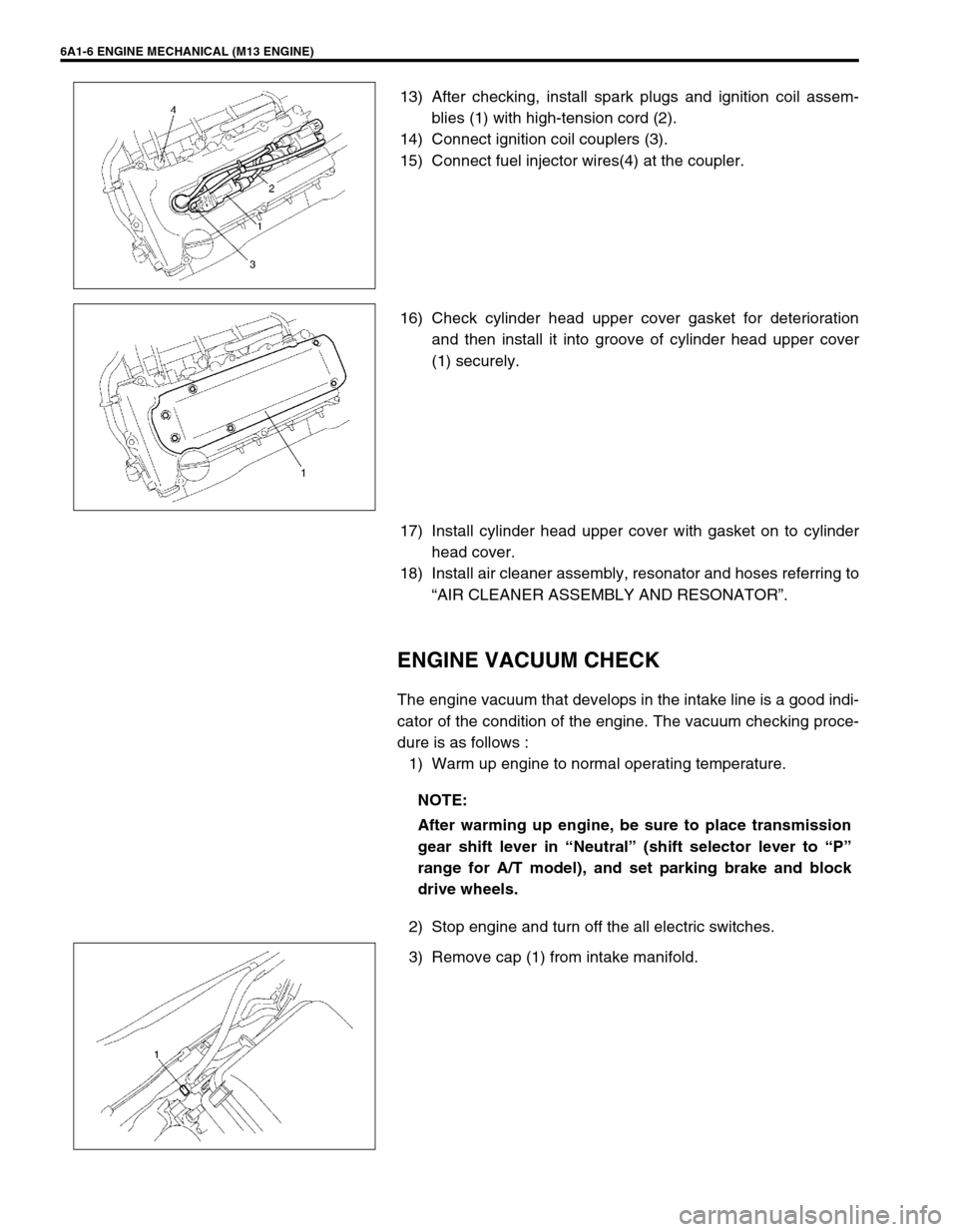
13) After checking, install spark plugs and ignition coil assem-
blies (1) with high-tension cord (2).
14) Connect ignition coil couplers (3).
15) Connect fuel injector wires(4) at the coupler.
16) Check cylinder head upper cover gasket for deterioration
and then install it into groove of cylinder head upper cover
(1) securely.
17) Install cylinder head upper cover with gasket on to cylinder
head cover.
18) Install air cleaner assembly, resonator and hoses referring to
“AIR CLEANER ASSEMBLY AND RESONATOR”.
ENGINE VACUUM CHECK
The engine vacuum that develops in the intake line is a good indi-
cator of the condition of the engine. The vacuum checking proce-
dure is as follows :
1) Warm up engine to normal operating temperature.
2) Stop engine and turn off the all electric switches.
3) Remove cap (1) from intake manifold.
NOTE:
After warming up engine, be sure to place transmission
gear shift lever in “Neutral” (shift selector lever to “P”
range for A/T model), and set parking brake and block
drive wheels.
Page 508 of 698

ENGINE MECHANICAL (M13 ENGINE) 6A1-7
4) Connect special tool (Vacuum gauge) to intake manifold.
Special tool
(A) : 09915-67310
5) Run engine at specified idle speed and read vacuum gauge.
Vacuum should be within specification.
Vacuum specification (at sea level)
: 59 – 73 kPa (45 – 55 cmHg, 17.7 – 21.6 inHg)
at specified idle speed
6) After checking, disconnect special tool (Vacuum gauge) from
intake manifold.
7) Install cap to intake manifold.
OIL PRESSURE CHECK
Oil level in oil pan
If oil level is low, add oil up to Full level mark (hole) on oil
level gauge.
Oil quality
If oil is discolored, or deteriorated, change it.
For particular oil to be used referring to the table in Section
0B.
Oil leaks
If leak is found, repair it.
1) Disconnect oil pressure switch coupler (1) and remove oil
pressure switch (2) from cylinder block.
NOTE:
Prior to checking oil pressure, check the following items.
1. Full level mark (hole)
2. Low level mark (hole)
Page 561 of 698

6A1-60 ENGINE MECHANICAL (M13 ENGINE)
Piston clearance:
Measure cylinder bore diameter and piston diameter to find
their difference which is piston clearance. Piston clearance
should be within specification as given below. If it is out of
specification, rebore cylinder and use oversize piston.
Piston clearance
: 0.032 – 0.061 mm (0.0013 – 0.0024 in.)
: 0.016 – 0.045 mm (0.0006 – 0.0018 in.) with coating
Ring groove clearance:
Before checking, piston grooves must be clean, dry and free
of carbon deposits.
Fit new piston ring (1) into piston groove, and measure clear-
ance between ring and ring land by using thickness gauge
(2). If clearance is out of limit, replace piston.
Ring groove clearance
Top ring
Standard : 0.03 – 0.07 mm (0.0012 – 0.0028 in.)
Limit : 0.12 mm (0.0047 in.)
2nd ring
Standard : 0.02 – 0.06 mm (0.0008 – 0.0024 in.)
Limit : 0.10 mm (0.0039 in.)
Oil ring
Standard : 0.03 – 0.17 mm (0.0012 – 0.0067 in.)
Piston Pin
Check piston pin, connecting rod small end bore and piston
bore for wear or damage, paying particular attention to con-
dition of small end bore bush. If pin, connecting rod small
end bore or piston bore is badly worn or damaged, replace
pin, connecting rod and/or piston. NOTE:
Cylinder bore diameters used here are measured in
thrust direction at two positions.
“a” : 19.5 mm (0.77 in.)
Page 564 of 698
ENGINE MECHANICAL (M13 ENGINE) 6A1-63
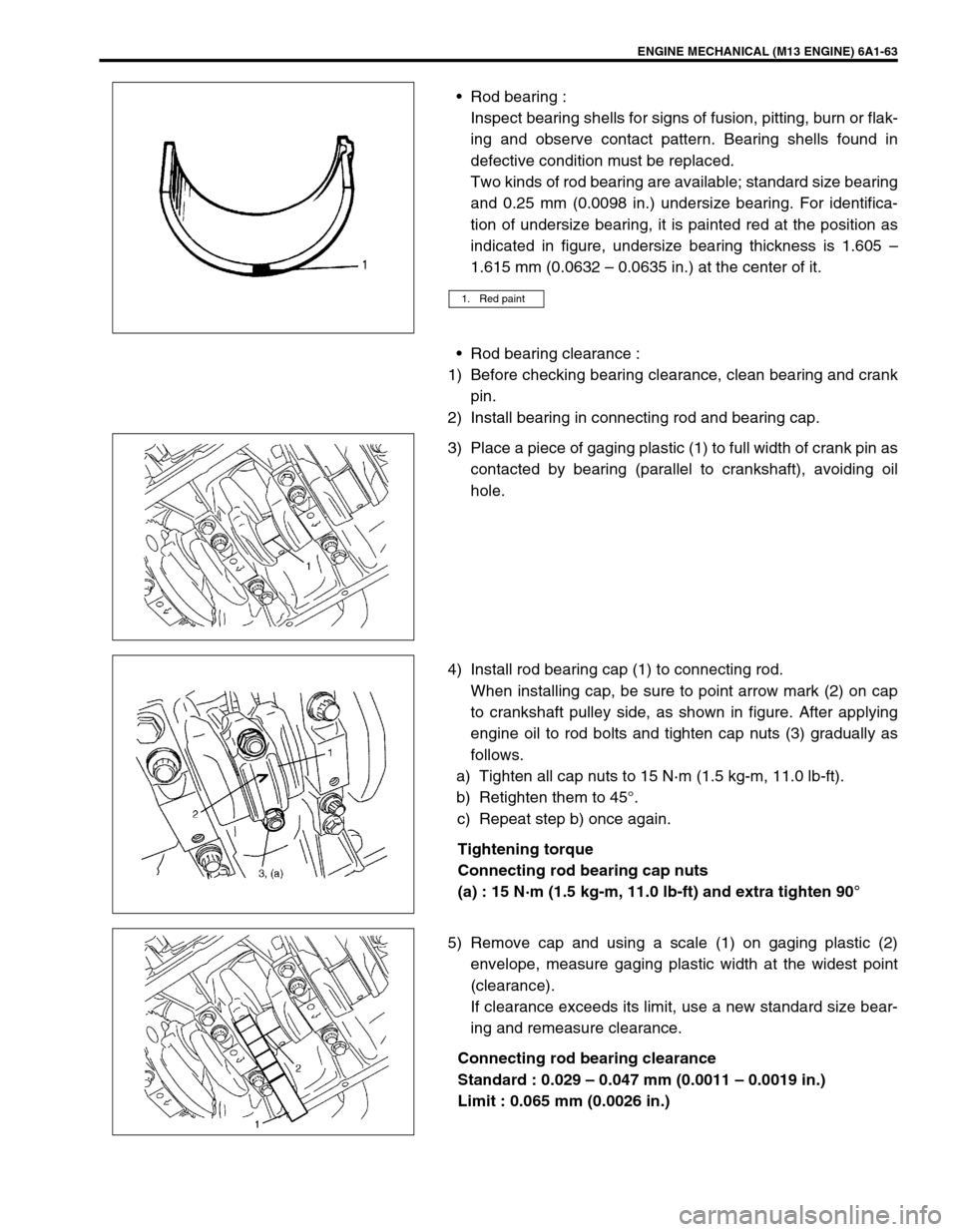
Rod bearing :
Inspect bearing shells for signs of fusion, pitting, burn or flak-
ing and observe contact pattern. Bearing shells found in
defective condition must be replaced.
Two kinds of rod bearing are available; standard size bearing
and 0.25 mm (0.0098 in.) undersize bearing. For identifica-
tion of undersize bearing, it is painted red at the position as
indicated in figure, undersize bearing thickness is 1.605 –
1.615 mm (0.0632 – 0.0635 in.) at the center of it.
Rod bearing clearance :
1) Before checking bearing clearance, clean bearing and crank
pin.
2) Install bearing in connecting rod and bearing cap.
3) Place a piece of gaging plastic (1) to full width of crank pin as
contacted by bearing (parallel to crankshaft), avoiding oil
hole.
4) Install rod bearing cap (1) to connecting rod.
When installing cap, be sure to point arrow mark (2) on cap
to crankshaft pulley side, as shown in figure. After applying
engine oil to rod bolts and tighten cap nuts (3) gradually as
follows.
a) Tighten all cap nuts to 15 N·m (1.5 kg-m, 11.0 lb-ft).
b) Retighten them to 45°.
c) Repeat step b) once again.
Tightening torque
Connecting rod bearing cap nuts
(a) : 15 N·m (1.5 kg-m, 11.0 lb-ft) and extra tighten 90°
5) Remove cap and using a scale (1) on gaging plastic (2)
envelope, measure gaging plastic width at the widest point
(clearance).
If clearance exceeds its limit, use a new standard size bear-
ing and remeasure clearance.
Connecting rod bearing clearance
Standard : 0.029 – 0.047 mm (0.0011 – 0.0019 in.)
Limit : 0.065 mm (0.0026 in.)
1. Red paint