length SUZUKI SWIFT 2000 1.G RG413 Service User Guide
[x] Cancel search | Manufacturer: SUZUKI, Model Year: 2000, Model line: SWIFT, Model: SUZUKI SWIFT 2000 1.GPages: 698, PDF Size: 16.01 MB
Page 282 of 698
BRAKES 5-9
EXCESSIVE PEDAL TRAVEL INSPECTION
1) Start engine.
2) Depress brake pedal a few times.
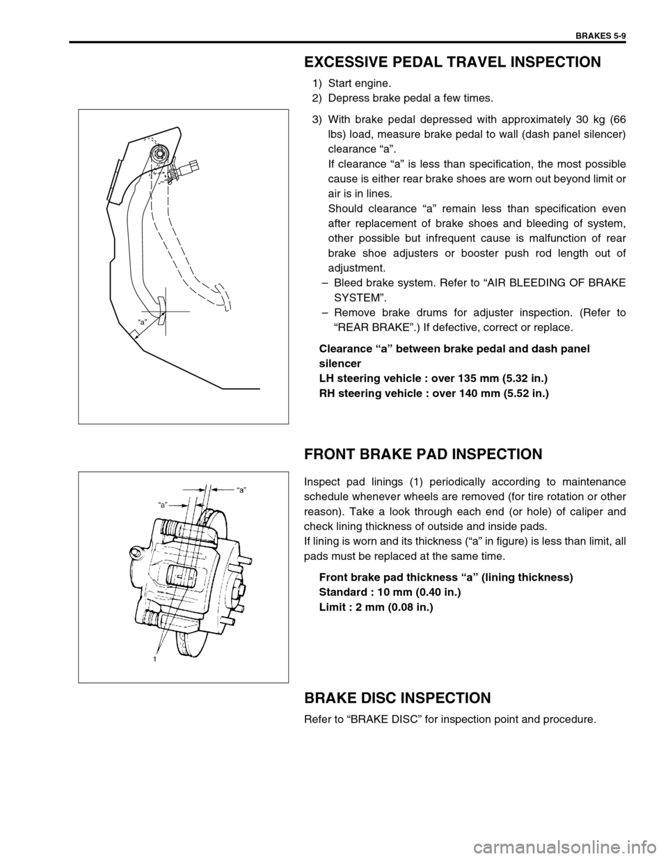
3) With brake pedal depressed with approximately 30 kg (66
lbs) load, measure brake pedal to wall (dash panel silencer)
clearance “a”.
If clearance “a” is less than specification, the most possible
cause is either rear brake shoes are worn out beyond limit or
air is in lines.
Should clearance “a” remain less than specification even
after replacement of brake shoes and bleeding of system,
other possible but infrequent cause is malfunction of rear
brake shoe adjusters or booster push rod length out of
adjustment.
–Bleed brake system. Refer to “AIR BLEEDING OF BRAKE
SYSTEM”.
–Remove brake drums for adjuster inspection. (Refer to
“REAR BRAKE”.) If defective, correct or replace.
Clearance “a” between brake pedal and dash panel
silencer
LH steering vehicle : over 135 mm (5.32 in.)
RH steering vehicle : over 140 mm (5.52 in.)
FRONT BRAKE PAD INSPECTION
Inspect pad linings (1) periodically according to maintenance
schedule whenever wheels are removed (for tire rotation or other
reason). Take a look through each end (or hole) of caliper and
check lining thickness of outside and inside pads.
If lining is worn and its thickness (“a” in figure) is less than limit, all
pads must be replaced at the same time.
Front brake pad thickness “a” (lining thickness)
Standard : 10 mm (0.40 in.)
Limit : 2 mm (0.08 in.)
BRAKE DISC INSPECTION
Refer to “BRAKE DISC” for inspection point and procedure.
“a”
Page 310 of 698
BRAKES 5-37
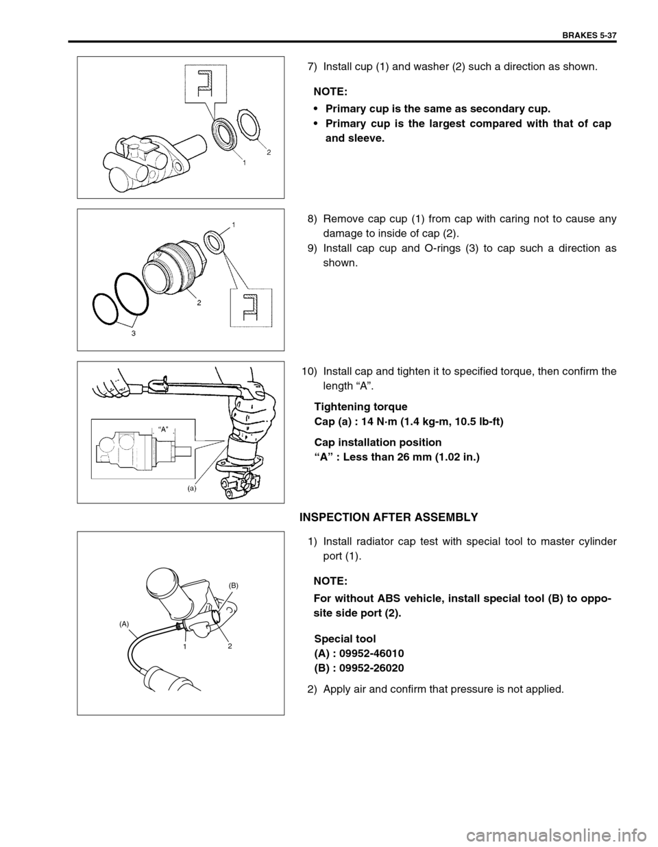
7) Install cup (1) and washer (2) such a direction as shown.
8) Remove cap cup (1) from cap with caring not to cause any
damage to inside of cap (2).
9) Install cap cup and O-rings (3) to cap such a direction as
shown.
10) Install cap and tighten it to specified torque, then confirm the
length “A”.
Tightening torque
Cap (a) : 14 N·m (1.4 kg-m, 10.5 lb-ft)
Cap installation position
“A” : Less than 26 mm (1.02 in.)
INSPECTION AFTER ASSEMBLY
1) Install radiator cap test with special tool to master cylinder
port (1).
Special tool
(A) : 09952-46010
(B) : 09952-26020
2) Apply air and confirm that pressure is not applied.NOTE:
Primary cup is the same as secondary cup.
Primary cup is the largest compared with that of cap
and sleeve.
NOTE:
For without ABS vehicle, install special tool (B) to oppo-
site side port (2).
1(B)
2 (A)
Page 312 of 698
BRAKES 5-39
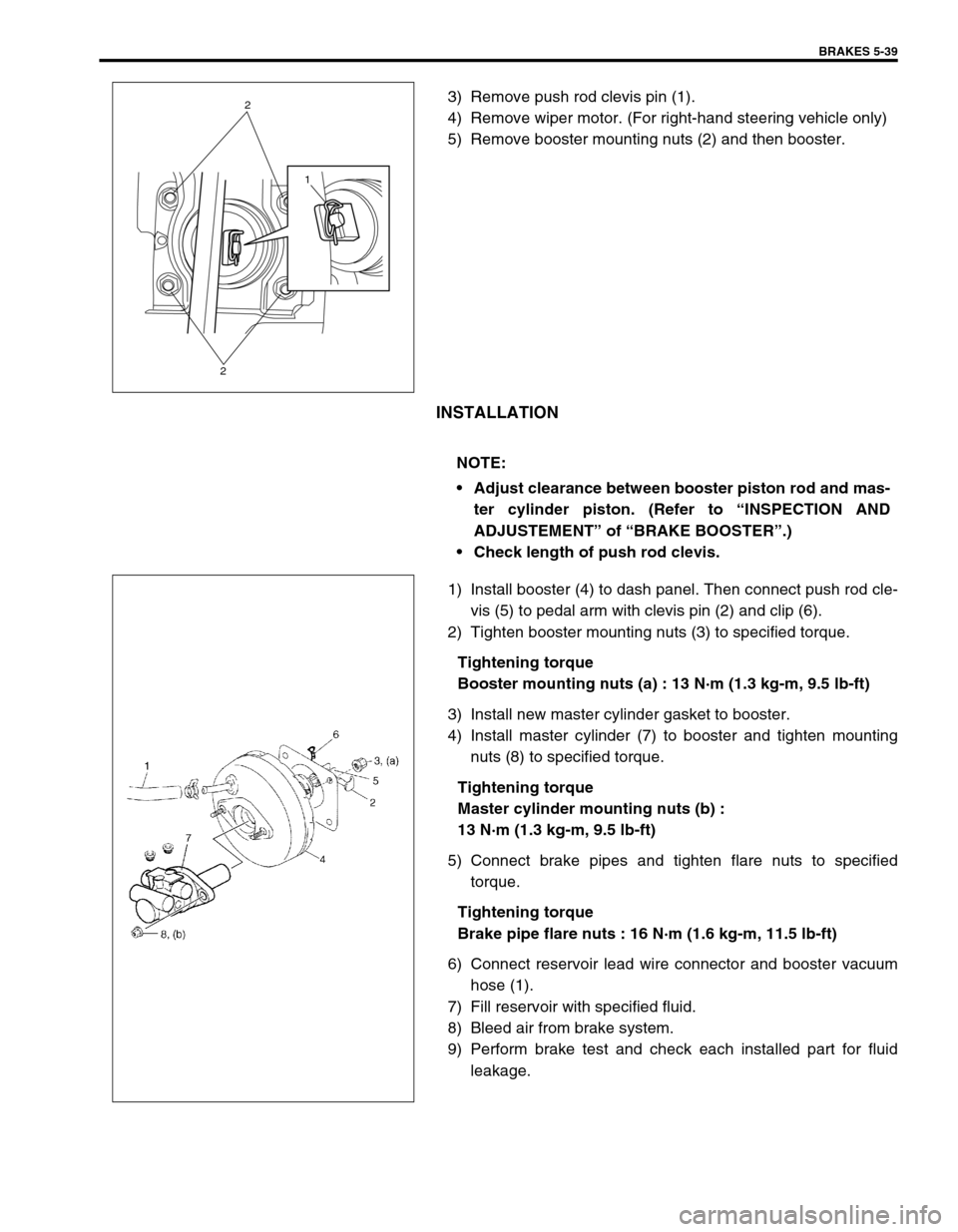
3) Remove push rod clevis pin (1).
4) Remove wiper motor. (For right-hand steering vehicle only)
5) Remove booster mounting nuts (2) and then booster.
INSTALLATION
1) Install booster (4) to dash panel. Then connect push rod cle-
vis (5) to pedal arm with clevis pin (2) and clip (6).
2) Tighten booster mounting nuts (3) to specified torque.
Tightening torque
Booster mounting nuts (a) : 13 N·m (1.3 kg-m, 9.5 lb-ft)
3) Install new master cylinder gasket to booster.
4) Install master cylinder (7) to booster and tighten mounting
nuts (8) to specified torque.
Tightening torque
Master cylinder mounting nuts (b) :
13 N·m (1.3 kg-m, 9.5 lb-ft)
5) Connect brake pipes and tighten flare nuts to specified
torque.
Tightening torque
Brake pipe flare nuts : 16 N·m (1.6 kg-m, 11.5 lb-ft)
6) Connect reservoir lead wire connector and booster vacuum
hose (1).
7) Fill reservoir with specified fluid.
8) Bleed air from brake system.
9) Perform brake test and check each installed part for fluid
leakage.
1
2
2
NOTE:
Adjust clearance between booster piston rod and mas-
ter cylinder piston. (Refer to “INSPECTION AND
ADJUSTEMENT” of “BRAKE BOOSTER”.)
Check length of push rod clevis.
Page 313 of 698

5-40 BRAKES
INSPECTION AND ADJUSTMENT
Installation Position Of Push Rod
If push rod clevis (1) has been removed, adjust distance between
booster installation surface (without including packing) and the
center of clevis pin hole to standard value “a” and tighten nut (2)
to specified torque.
Distance “a” between center of booster clevis pin hole
and booster surface
Standard : 97 - 98 mm (3.82 - 3.86 in.)
Tightening torque
Clevis pin lock nut (a) : 19 N·m (1.9 kg-m, 14.0 lb-ft)
Clearance Between Booster Piston Rod And Master Cylin-
der Piston
The length of booster piston rod (1) is adjusted to provide speci-
fied clearance “a” between piston rod (1) end and master cylinder
piston (2).
Before measuring clearance, push piston rod several times
so as to make sure reaction disc is in place.
Keep inside of booster at atmospheric pressure for measure-
ment.
Measure length “a” of piston rod, i.e. distance between piston rod
and mating surface of booster-to-master cylinder.
Length “a” of piston rod
: 30.3 - 30.5 mm (1.193 - 1.200 in.)
If measurement is out of specification, adjust piston rod by turning
adjusting screw of piston rod.
Special tool
(B) : 09952-16020
NOTE:
Remove gasket from booster, if equipped.
Page 322 of 698
BRAKES 5-49
INSTALLATION
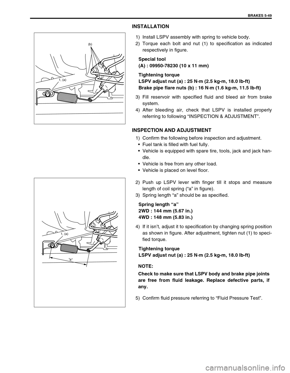
1) Install LSPV assembly with spring to vehicle body.
2) Torque each bolt and nut (1) to specification as indicated
respectively in figure.
Special tool
(A) : 09950-78230 (10 x 11 mm)
Tightening torque
LSPV adjust nut (a) : 25 N·m (2.5 kg-m, 18.0 lb-ft)
Brake pipe flare nuts (b) : 16 N·m (1.6 kg-m, 11.5 lb-ft)
3) Fill reservoir with specified fluid and bleed air from brake
system.
4) After bleeding air, check that LSPV is installed properly
referring to following “INSPECTION & ADJUSTMENT”.
INSPECTION AND ADJUSTMENT
1) Confirm the following before inspection and adjustment.
Fuel tank is filled with fuel fully.
Vehicle is equipped with spare tire, tools, jack and jack han-
dle.
Vehicle is free from any other load.
Vehicle is placed on level floor.
2) Push up LSPV lever with finger till it stops and measure
length of coil spring (“a” in figure).
3) Spring length “a” should be as specified.
Spring length “a”
2WD : 144 mm (5.67 in.)
4WD : 148 mm (5.83 in.)
4) If it isn’t, adjust it to specification by changing spring position
as shown in figure. After adjustment, tighten nut (1) to speci-
fied torque.
Tightening torque
LSPV adjust nut (a) : 25 N·m (2.5 kg-m, 18.0 lb-ft)
5) Confirm fluid pressure referring to “Fluid Pressure Test”.
1, (a)
(b)
NOTE:
Check to make sure that LSPV body and brake pipe joints
are free from fluid leakage. Replace defective parts, if
any.
1, (a)
“a”
Page 549 of 698

6A1-48 ENGINE MECHANICAL (M13 ENGINE)
INSPECTION
Valve Guides
Using a micrometer and bore gauge, take diameter readings on
valve stems and guides to check stem-to-guide clearance. Be
sure to take reading at more than one place along the length of
each stem and guide.
If clearance exceeds limit, replace valve and valve guide.
Valve stem-to-guide clearance
Valve stem diameter [A]
Valve guide bore [B] standard
In and Ex : 6.000 – 6.012 mm (0.2362 – 0.2367 in.) for 69G
type valve
In and Ex : 5.485 – 5.510 mm (0.2159 – 0.2169 in.) for 54G
type valve
If bore gauge is not available, check end deflection of valve stem
with a dial gauge instead.
Move stem end in directions (1) and (2) to measure end deflec-
tion.
If deflection exceeds its limit, replace valve stem and valve guide.
Valve stem end deflection limit
In : 0.14 mm (0.005 in.)
Ex : 0.18 mm (0.007 in.)Valve type Standard Limit
69GIn0.020 – 0.047 mm
(0.0008 – 0.0019 in.)0.07 mm
(0.0028 in.)
Ex0.045 – 0.072 mm
(0.0018 – 0.0028 in.)0.09 mm
(0.0035 in.)
54GIn0.020 – 0.030 mm
(0.0008 – 0.0012 in.)0.05 mm
(0.0017 in.)
Ex0.045 – 0.055 mm
(0.0018 – 0.0022 in.)0.07 mm
(0.0028 in.)
Valve type Standard
69GIn5.965 – 5.980 mm
(0.2348 – 0.2354 in.)
Ex5.940 – 5.955 mm
(0.2339 – 0.2344 in.)
54GIn5.465 – 5.480 mm
(0.2152 – 0.2157 in.)
Ex5.440 – 5.455 mm
(0.2142 – 0.2148 in.)
1. Emboss mark 54G or 69G
Page 553 of 698
6A1-52 ENGINE MECHANICAL (M13 ENGINE)
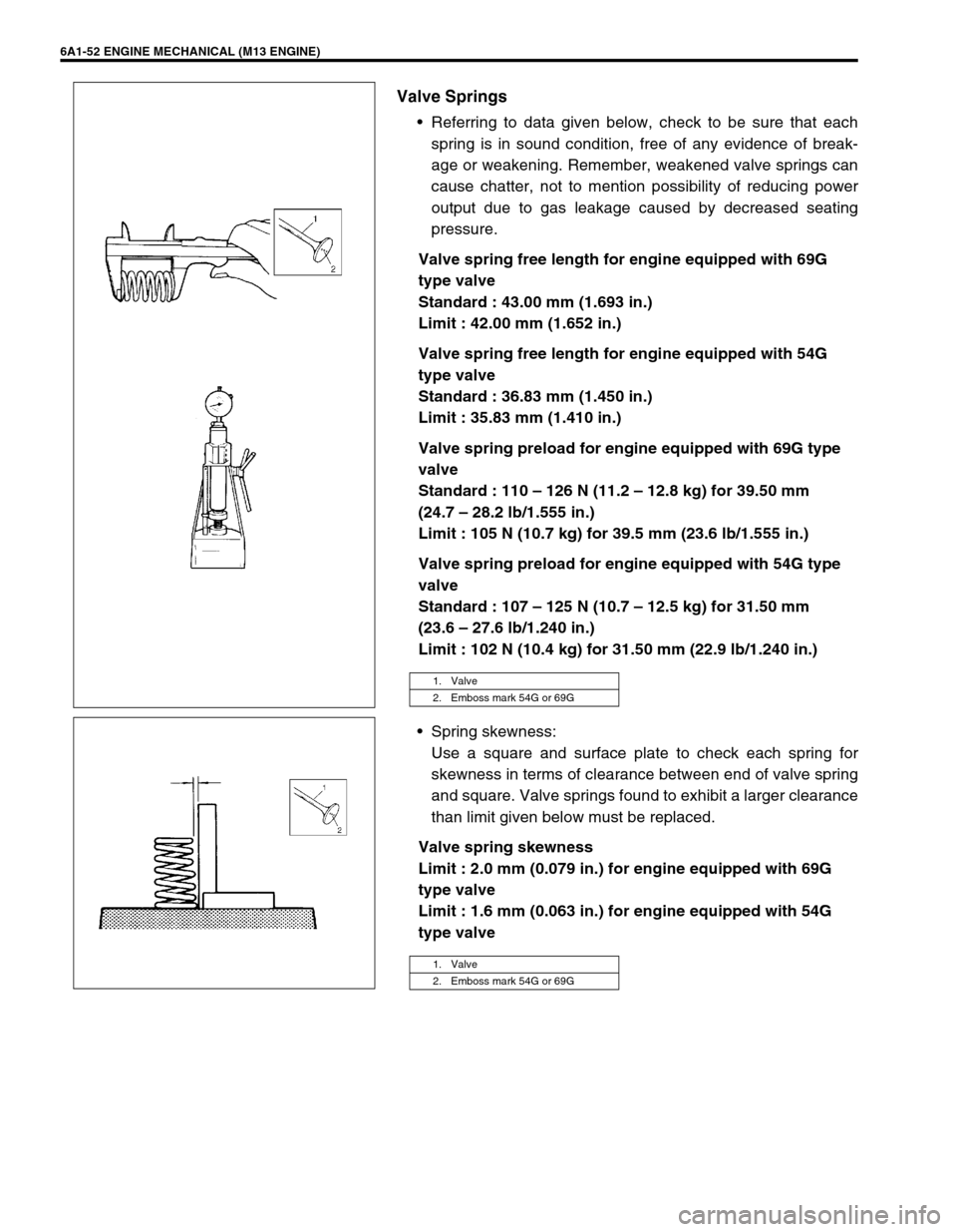
Valve Springs
Referring to data given below, check to be sure that each
spring is in sound condition, free of any evidence of break-
age or weakening. Remember, weakened valve springs can
cause chatter, not to mention possibility of reducing power
output due to gas leakage caused by decreased seating
pressure.
Valve spring free length for engine equipped with 69G
type valve
Standard : 43.00 mm (1.693 in.)
Limit : 42.00 mm (1.652 in.)
Valve spring free length for engine equipped with 54G
type valve
Standard : 36.83 mm (1.450 in.)
Limit : 35.83 mm (1.410 in.)
Valve spring preload for engine equipped with 69G type
valve
Standard : 110 – 126 N (11.2 – 12.8 kg) for 39.50 mm
(24.7 – 28.2 lb/1.555 in.)
Limit : 105 N (10.7 kg) for 39.5 mm (23.6 lb/1.555 in.)
Valve spring preload for engine equipped with 54G type
valve
Standard : 107 – 125 N (10.7 – 12.5 kg) for 31.50 mm
(23.6 – 27.6 lb/1.240 in.)
Limit : 102 N (10.4 kg) for 31.50 mm (22.9 lb/1.240 in.)
Spring skewness:
Use a square and surface plate to check each spring for
skewness in terms of clearance between end of valve spring
and square. Valve springs found to exhibit a larger clearance
than limit given below must be replaced.
Valve spring skewness
Limit : 2.0 mm (0.079 in.) for engine equipped with 69G
type valve
Limit : 1.6 mm (0.063 in.) for engine equipped with 54G
type valve
1. Valve
2. Emboss mark 54G or 69G
1. Valve
2. Emboss mark 54G or 69G
Page 577 of 698

6A1-76 ENGINE MECHANICAL (M13 ENGINE)
Use a dial gauge to read displacement in axial (thrust) direction of
crankshaft.
If its limit is exceeded, replace thrust bearing with new standard
one or oversize one to obtain standard thrust play.
Crankshaft thrust play
Standard : 0.11 – 0.31 mm (0.0043 – 0.0122 in.)
Limit : 0.35 mm (0.0138 in.)
Out-of-round and taper (uneven wear) of journals
An unevenly worn crankshaft journal shows up as a difference in
diameter at a cross section or along its length (or both). This dif-
ference, if any, is determined by taking micrometer readings. If
any one of journals is badly damaged or if amount of uneven wear
in the sense explained above exceeds its limit, regrind or replace
crankshaft.
Crankshaft out-of-round and taper
Limit : 0.01 mm (0.0004 in.)
Out-of-round : A – B
Taper : a – b
Main Bearings
General information
Service main bearings are available in standard size and
0.25 mm (0.0098 in.) undersize, and each of them has 5
kinds of bearings differing in tolerance.
Upper half of bearing (1) has an oil groove (2) as shown in
figure.
Install this half with oil groove to cylinder block.
Lower half of bearing does not have an oil groove.
Visual inspection
Check bearings for pitting, scratches, wear or damage.
If any malcondition is found, replace both upper and lower halves.
Never replace either half without replacing the other half.
Main bearing clearance
Check clearance by using gaging plastic according to the follow-
ing procedure.
1) Remove bearing caps.
2) Clean bearings and main journals.
Page 680 of 698
6G-8 CRANKING SYSTEM
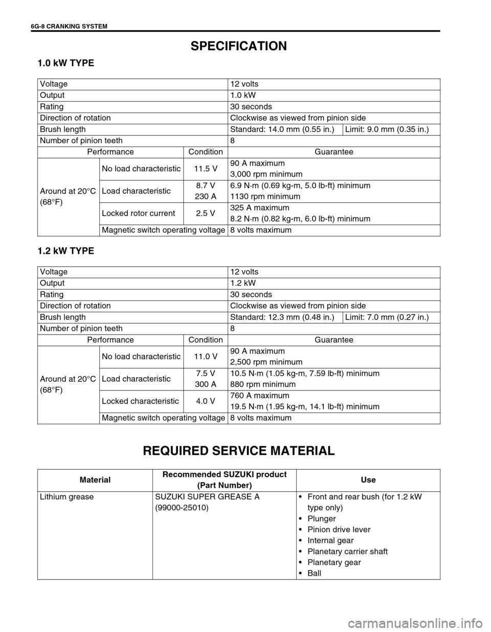
SPECIFICATION
1.0 kW TYPE
1.2 kW TYPE
REQUIRED SERVICE MATERIAL
Voltage 12 volts
Output 1.0 kW
Rating 30 seconds
Direction of rotation Clockwise as viewed from pinion side
Brush length Standard: 14.0 mm (0.55 in.) Limit: 9.0 mm (0.35 in.)
Number of pinion teeth 8
Performance Condition Guarantee
Around at 20°C
(68°F)No load characteristic 11.5 V90 A maximum
3,000 rpm minimum
Load characteristic8.7 V
230 A6.9 N·m (0.69 kg-m, 5.0 lb-ft) minimum
1130 rpm minimum
Locked rotor current 2.5 V325 A maximum
8.2 N·m (0.82 kg-m, 6.0 lb-ft) minimum
Magnetic switch operating voltage 8 volts maximum
Voltage 12 volts
Output 1.2 kW
Rating 30 seconds
Direction of rotation Clockwise as viewed from pinion side
Brush length Standard: 12.3 mm (0.48 in.) Limit: 7.0 mm (0.27 in.)
Number of pinion teeth 8
Performance Condition Guarantee
Around at 20°C
(68°F)No load characteristic 11.0 V90 A maximum
2,500 rpm minimum
Load characteristic7.5 V
300 A10.5 N·m (1.05 kg-m, 7.59 lb-ft) minimum
880 rpm minimum
Locked characteristic 4.0 V760 A maximum
19.5 N·m (1.95 kg-m, 14.1 lb-ft) minimum
Magnetic switch operating voltage 8 volts maximum
MaterialRecommended SUZUKI product
(Part Number)Use
Lithium grease SUZUKI SUPER GREASE A
(99000-25010)Front and rear bush (for 1.2 kW
type only)
Plunger
Pinion drive lever
Internal gear
Planetary carrier shaft
Planetary gear
Ball
Page 693 of 698
CHARGING SYSTEM 6H-13
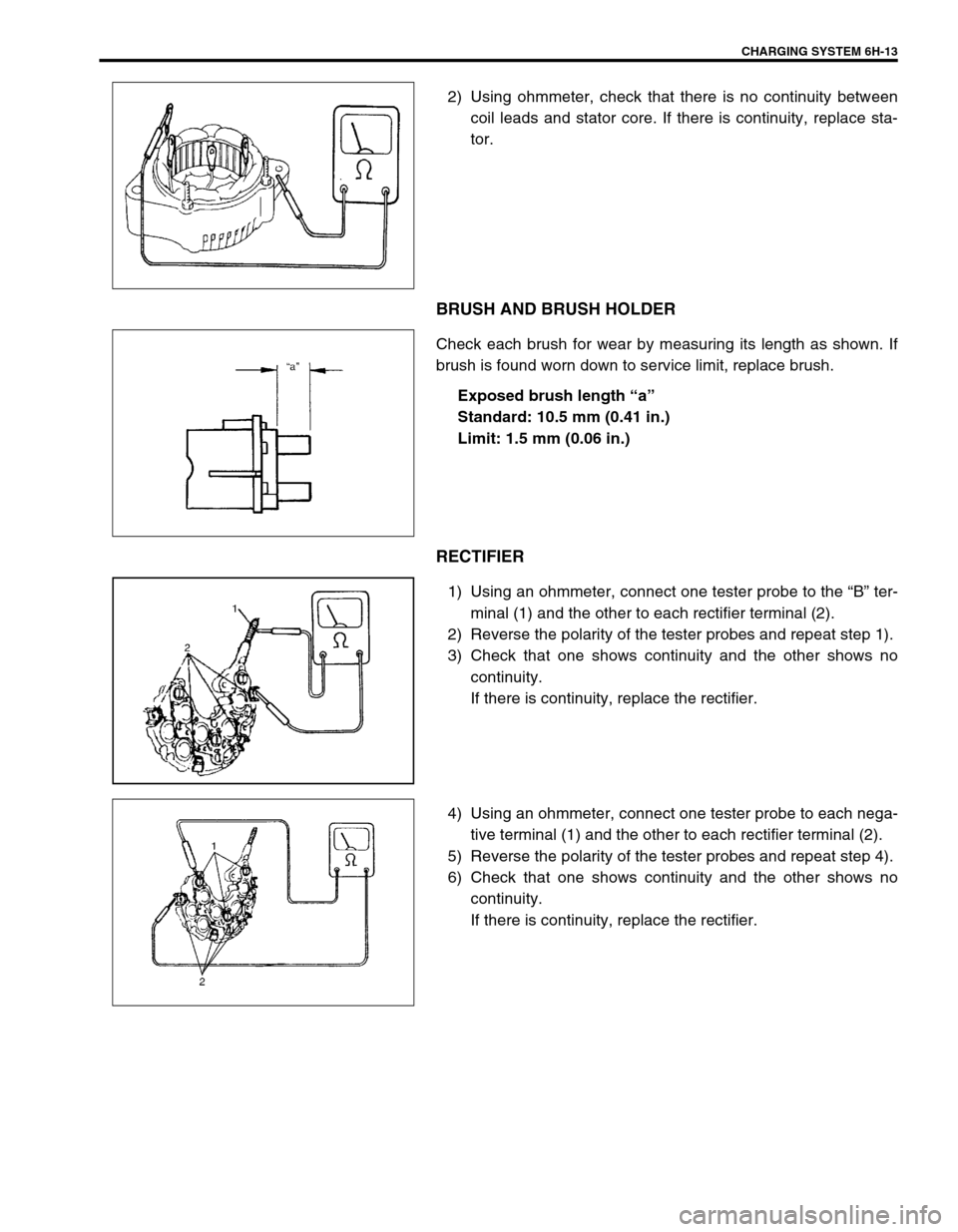
2) Using ohmmeter, check that there is no continuity between
coil leads and stator core. If there is continuity, replace sta-
tor.
BRUSH AND BRUSH HOLDER
Check each brush for wear by measuring its length as shown. If
brush is found worn down to service limit, replace brush.
Exposed brush length “a”
Standard: 10.5 mm (0.41 in.)
Limit: 1.5 mm (0.06 in.)
RECTIFIER
1) Using an ohmmeter, connect one tester probe to the “B” ter-
minal (1) and the other to each rectifier terminal (2).
2) Reverse the polarity of the tester probes and repeat step 1).
3) Check that one shows continuity and the other shows no
continuity.
If there is continuity, replace the rectifier.
4) Using an ohmmeter, connect one tester probe to each nega-
tive terminal (1) and the other to each rectifier terminal (2).
5) Reverse the polarity of the tester probes and repeat step 4).
6) Check that one shows continuity and the other shows no
continuity.
If there is continuity, replace the rectifier.