length SUZUKI SWIFT 2000 1.G RG413 Service Workshop Manual
[x] Cancel search | Manufacturer: SUZUKI, Model Year: 2000, Model line: SWIFT, Model: SUZUKI SWIFT 2000 1.GPages: 698, PDF Size: 16.01 MB
Page 72 of 698
AIR CONDITIONING (OPTIONAL) 1B-7
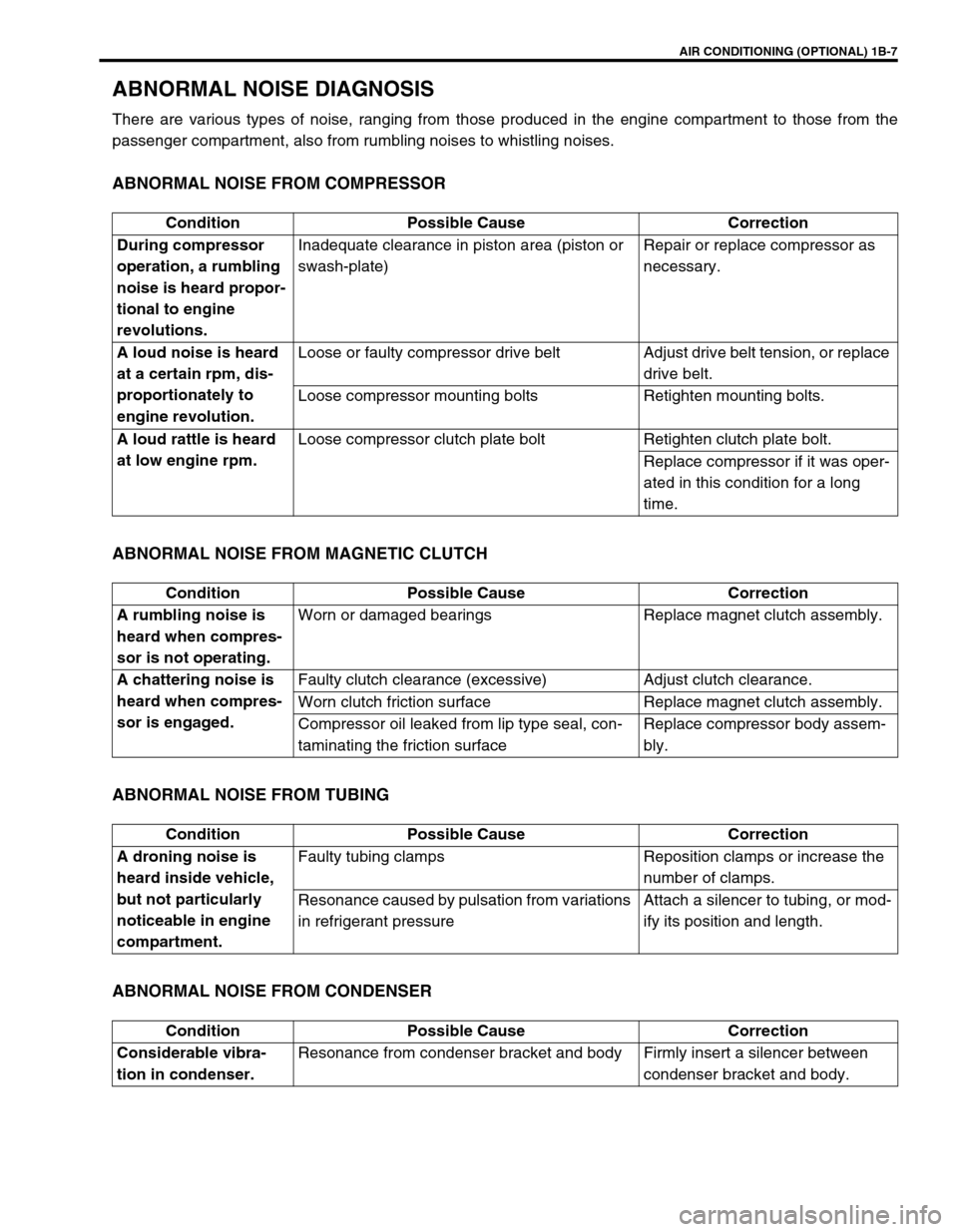
ABNORMAL NOISE DIAGNOSIS
There are various types of noise, ranging from those produced in the engine compartment to those from the
passenger compartment, also from rumbling noises to whistling noises.
ABNORMAL NOISE FROM COMPRESSOR
ABNORMAL NOISE FROM MAGNETIC CLUTCH
ABNORMAL NOISE FROM TUBING
ABNORMAL NOISE FROM CONDENSER
Condition Possible Cause Correction
During compressor
operation, a rumbling
noise is heard propor-
tional to engine
revolutions.Inadequate clearance in piston area (piston or
swash-plate)Repair or replace compressor as
necessary.
A loud noise is heard
at a certain rpm, dis-
proportionately to
engine revolution.Loose or faulty compressor drive belt Adjust drive belt tension, or replace
drive belt.
Loose compressor mounting bolts Retighten mounting bolts.
A loud rattle is heard
at low engine rpm.Loose compressor clutch plate bolt Retighten clutch plate bolt.
Replace compressor if it was oper-
ated in this condition for a long
time.
Condition Possible Cause Correction
A rumbling noise is
heard when compres-
sor is not operating.Worn or damaged bearings Replace magnet clutch assembly.
A chattering noise is
heard when compres-
sor is engaged.Faulty clutch clearance (excessive) Adjust clutch clearance.
Worn clutch friction surface Replace magnet clutch assembly.
Compressor oil leaked from lip type seal, con-
taminating the friction surfaceReplace compressor body assem-
bly.
Condition Possible Cause Correction
A droning noise is
heard inside vehicle,
but not particularly
noticeable in engine
compartment.Faulty tubing clamps Reposition clamps or increase the
number of clamps.
Resonance caused by pulsation from variations
in refrigerant pressureAttach a silencer to tubing, or mod-
ify its position and length.
Condition Possible Cause Correction
Considerable vibra-
tion in condenser.Resonance from condenser bracket and body Firmly insert a silencer between
condenser bracket and body.
Page 120 of 698
FRONT END ALIGNMENT 3A-3
DIAGNOSIS
DIAGNOSIS TABLE
For the details, refer to Section 3.
PRELIMINARY CHECKS PRIOR TO ADJUSTING FRONT ALIGNMENT
Steering and vibration complaints are not always the result of improper alignment. An additional item to be
checked is the possibility of tire lead due to worn or improperly manufactured tires. “Lead” is the deviation of the
vehicle from a straight path on a level road without hand pressure on the steering wheel. Procedure for deter-
mining the presence of a tire lead problem contains in SECTION 3. Before making any adjustment affecting toe
setting, the following checks and inspections should be made to ensure correctness of alignment readings and
alignment adjustments:
1) Check all tires for proper inflation pressures and approximately the same tread wear.
2) Check for loose of ball joints. Check tie rod ends; if excessive looseness is noted, it must be corrected
before adjusting.
3) Check for run-out of wheels and tires.
4) Check vehicle trim heights; if out of limits and a correction is to be made, it must be made before adjusting
toe.
5) Check for loose of suspension arms.
6) Check for loose or missing stabilizer bar attachments.
7) Consideration must be given to excess loads, such as tool boxes. If this excess load is normally carried in
vehicle, it should remain in vehicle during alignment checks.
8) Consider condition of equipment being used to check alignment and follow manufacturer's instructions.
9) Regardless of equipment used to check alignment, vehicle must be on a level surface both fore and aft and
transversely.
TOE ADJUSTMENT
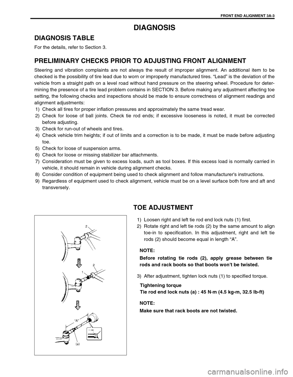
1) Loosen right and left tie rod end lock nuts (1) first.
2) Rotate right and left tie rods (2) by the same amount to align
toe-in to specification. In this adjustment, right and left tie
rods (2) should become equal in length “A”.
3) After adjustment, tighten lock nuts (1) to specified torque.
Tightening torque
Tie rod end lock nuts (a) : 45 N·m (4.5 kg-m, 32.5 lb-ft) NOTE:
Before rotating tie rods (2), apply grease between tie
rods and rack boots so that boots won't be twisted.
NOTE:
Make sure that rack boots are not twisted.
Page 121 of 698
3A-4 FRONT END ALIGNMENT
CAMBER AND CASTER CHECK AND
ADJUSTMENT
Should camber or caster be found out of specifications upon
inspection, locate its cause first.
If it is in damaged, loose, bent, dented or worn suspension parts,
they should be replaced.
If it is in vehicle body, repair it so as to attain specifications.
STEERING ANGLE CHECK AND ADJUST-
MENT
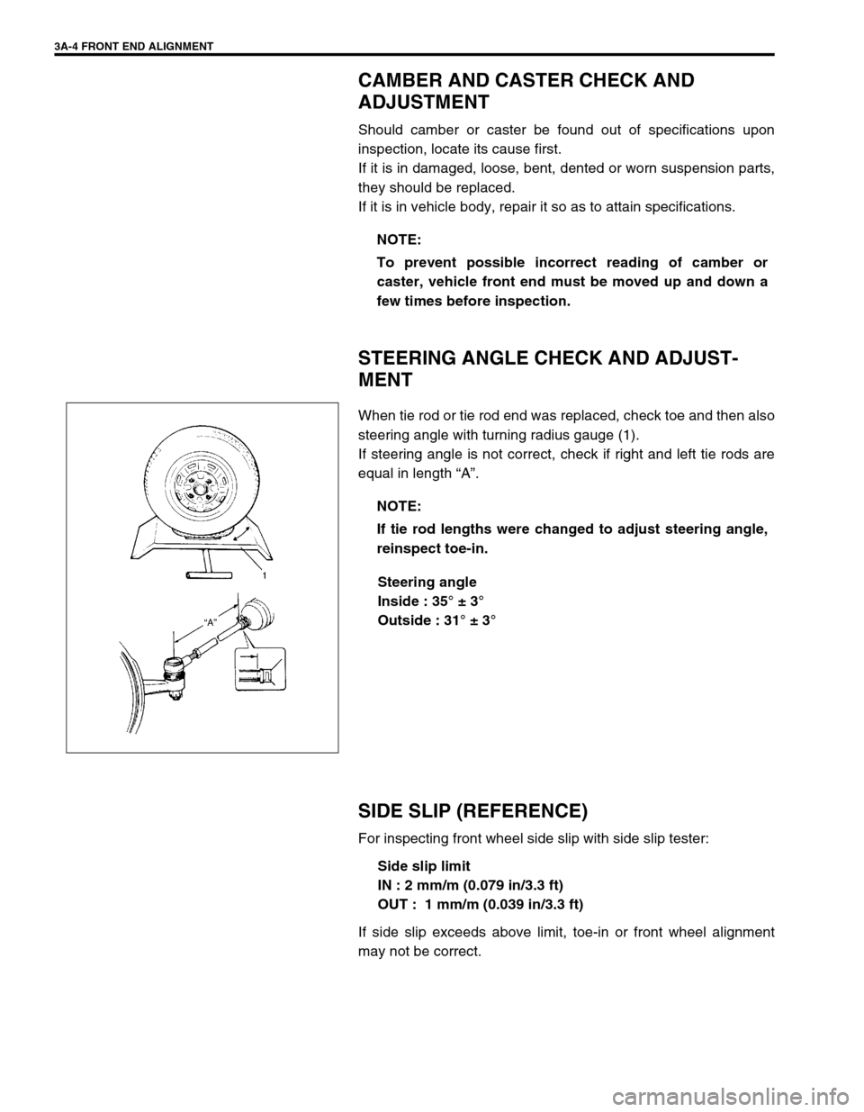
When tie rod or tie rod end was replaced, check toe and then also
steering angle with turning radius gauge (1).
If steering angle is not correct, check if right and left tie rods are
equal in length “A”.
Steering angle
Inside : 35° ± 3°
Outside : 31° ± 3°
SIDE SLIP (REFERENCE)
For inspecting front wheel side slip with side slip tester:
Side slip limit
IN : 2 mm/m (0.079 in/3.3 ft)
OUT : 1 mm/m (0.039 in/3.3 ft)
If side slip exceeds above limit, toe-in or front wheel alignment
may not be correct.NOTE:
To prevent possible incorrect reading of camber or
caster, vehicle front end must be moved up and down a
few times before inspection.
NOTE:
If tie rod lengths were changed to adjust steering angle,
reinspect toe-in.
Page 133 of 698
3B-12 MANUAL RACK AND PINION
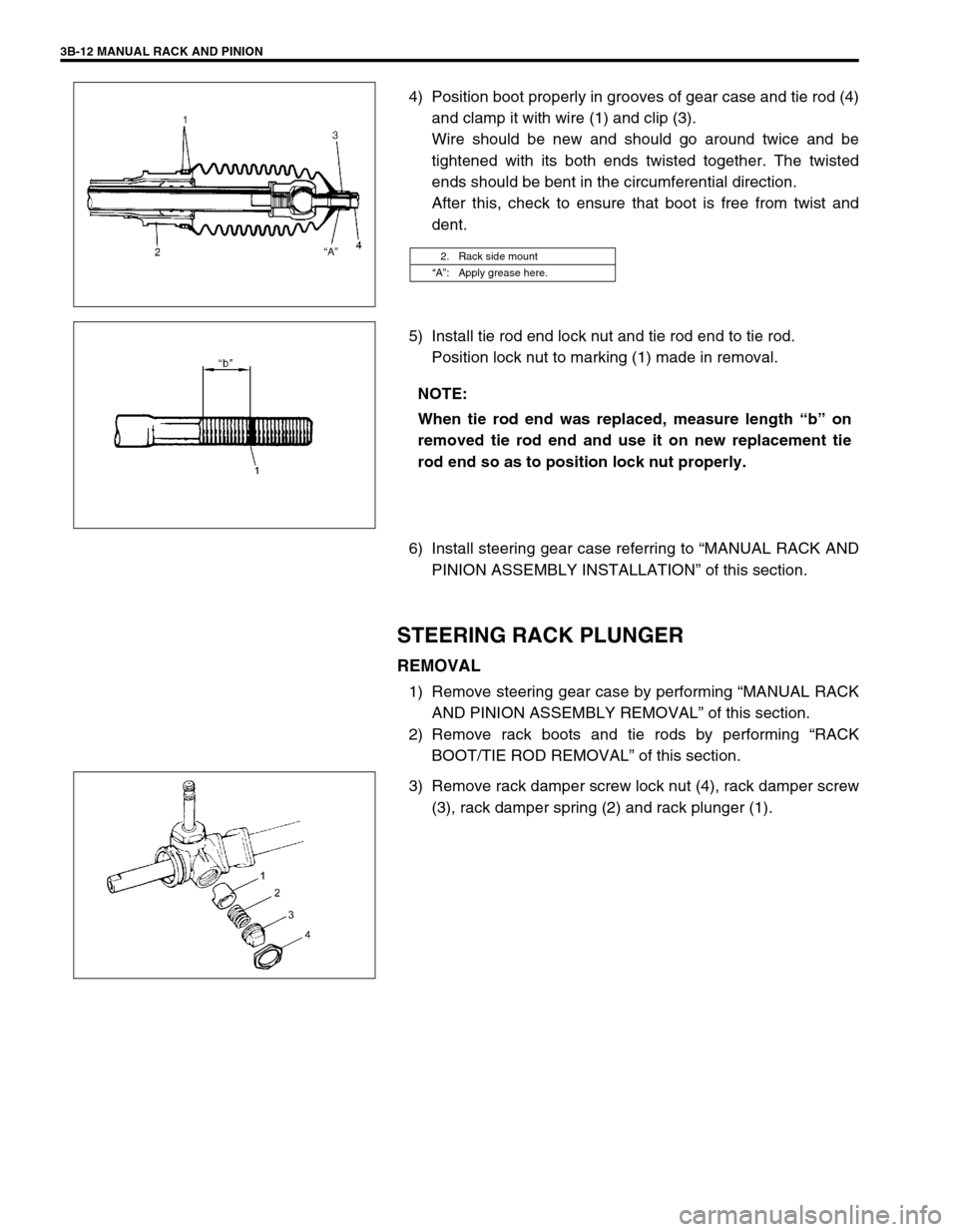
4) Position boot properly in grooves of gear case and tie rod (4)
and clamp it with wire (1) and clip (3).
Wire should be new and should go around twice and be
tightened with its both ends twisted together. The twisted
ends should be bent in the circumferential direction.
After this, check to ensure that boot is free from twist and
dent.
5) Install tie rod end lock nut and tie rod end to tie rod.
Position lock nut to marking (1) made in removal.
6) Install steering gear case referring to “MANUAL RACK AND
PINION ASSEMBLY INSTALLATION” of this section.
STEERING RACK PLUNGER
REMOVAL
1) Remove steering gear case by performing “MANUAL RACK
AND PINION ASSEMBLY REMOVAL” of this section.
2) Remove rack boots and tie rods by performing “RACK
BOOT/TIE ROD REMOVAL” of this section.
3) Remove rack damper screw lock nut (4), rack damper screw
(3), rack damper spring (2) and rack plunger (1).
2. Rack side mount
“A”: Apply grease here.
NOTE:
When tie rod end was replaced, measure length “b” on
removed tie rod end and use it on new replacement tie
rod end so as to position lock nut properly.
Page 175 of 698
3C-2 STEERING WHEEL AND COLUMN
GENERAL DESCRIPTION
STEERING COLUMN
This double tube type steering column has following three important features in addition to the steering function
:
The column is energy absorbing, designed to compress in a front-end collision.
The ignition switch and lock are mounted conveniently on this column.
With the column mounted lock, the ignition and steering operations can be locked to inhibit theft of the vehi-
cle.
To insure the energy absorbing action, it is important that only the specified screws, bolts, and nuts be used as
designated and that they are tightened to the specified torque.
When the column assembly is removed from the vehicle, special care must be taken in handling it. Use of a
steering wheel puller other than the one recommended in this manual or a sharp blow on the end of the steering
shaft, leaning on the assembly, or dropping the assembly could shear the plastic shear pins which maintain col-
umn length and position.
STEERING WHEEL AND DRIVER AIR BAG (INFLATOR) MODULE
The driver air bag (inflator) module is one of the supplemental restraint (air bag) system components and is
mounted to the center of the steering wheel. During certain frontal crashes, the air bag system supplements the
restraint of the driver’s and passenger’s seat belts by deploying the air bags.
The air bag (inflator) module should be handled with care to prevent accidental deployment. When servicing, be
sure to observe all WARNINGS and CAUTIONS and “SERVICE PRECAUTIONS” under “ON-VEHICLE SER-
VICE” in Section 10B.
DIAGNOSIS
For maintenance service of the steering wheel and column, refer to Section 0B.
For diagnosis of the steering wheel and column, refer to Section 3.
For diagnosis of the air bag system, refer to Section 10B.
INSPECTION AND REPAIR REQUIRED AFTER ACCIDENT
After an accident, whether the air bag has been deployed or not, be sure to perform checks, inspections and
repairs described under “CHECKING STEERING COLUMN ASSEMBLY AND LOWER SHAFT FOR ACCI-
DENT DAMAGE” as well as “REPAIRS AND INSPECTIONS REQUIRED AFTER ACCIDENT” under “DIAGNO-
SIS” in Section 10B.
Page 179 of 698
3C-6 STEERING WHEEL AND COLUMN
STEERING WHEEL
REMOVAL
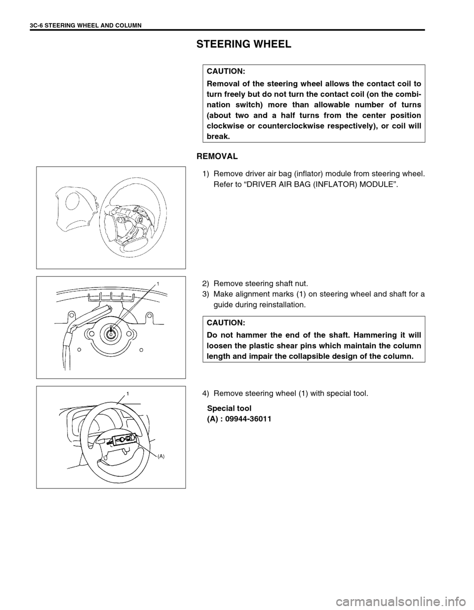
1) Remove driver air bag (inflator) module from steering wheel.
Refer to “DRIVER AIR BAG (INFLATOR) MODULE”.
2) Remove steering shaft nut.
3) Make alignment marks (1) on steering wheel and shaft for a
guide during reinstallation.
4) Remove steering wheel (1) with special tool.
Special tool
(A) : 09944-36011 CAUTION:
Removal of the steering wheel allows the contact coil to
turn freely but do not turn the contact coil (on the combi-
nation switch) more than allowable number of turns
(about two and a half turns from the center position
clockwise or counterclockwise respectively), or coil will
break.
CAUTION:
Do not hammer the end of the shaft. Hammering it will
loosen the plastic shear pins which maintain the column
length and impair the collapsible design of the column.
Page 183 of 698
3C-10 STEERING WHEEL AND COLUMN
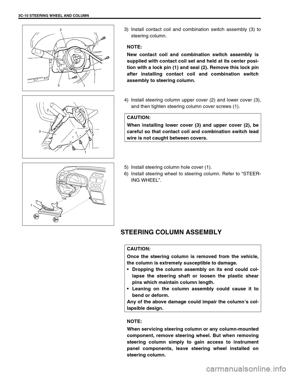
3) Install contact coil and combination switch assembly (3) to
steering column.
4) Install steering column upper cover (2) and lower cover (3),
and then tighten steering column cover screws (1).
5) Install steering column hole cover (1).
6) Install steering wheel to steering column. Refer to “STEER-
ING WHEEL”.
STEERING COLUMN ASSEMBLY
NOTE:
New contact coil and combination switch assembly is
supplied with contact coil set and held at its center posi-
tion with a lock pin (1) and seal (2). Remove this lock pin
after installing contact coil and combination switch
assembly to steering column.
CAUTION:
When installing lower cover (3) and upper cover (2), be
careful so that contact coil and combination switch lead
wire is not caught between covers.
1
CAUTION:
Once the steering column is removed from the vehicle,
the column is extremely susceptible to damage.
Dropping the column assembly on its end could col-
lapse the steering shaft or loosen the plastic shear
pins which maintain column length.
Leaning on the column assembly could cause it to
bend or deform.
Any of the above damage could impair the column’s col-
lapsible design.
NOTE:
When servicing steering column or any column-mounted
component, remove steering wheel. But when removing
steering column simply to gain access to instrument
panel components, leave steering wheel installed on
steering column.
Page 192 of 698
STEERING WHEEL AND COLUMN 3C-19
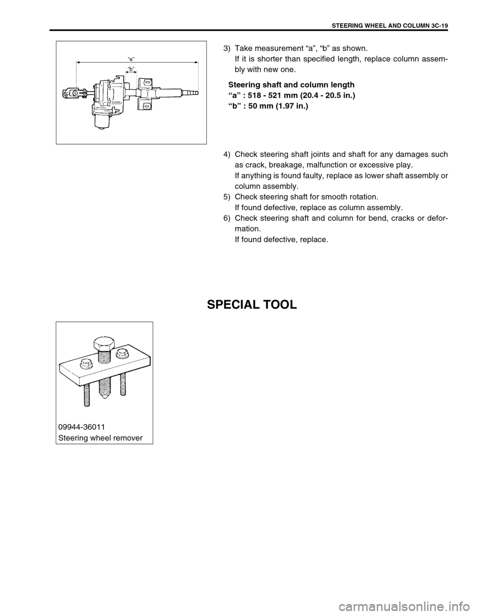
3) Take measurement “a”, “b” as shown.
If it is shorter than specified length, replace column assem-
bly with new one.
Steering shaft and column length
“a” : 518 - 521 mm (20.4 - 20.5 in.)
“b” : 50 mm (1.97 in.)
4) Check steering shaft joints and shaft for any damages such
as crack, breakage, malfunction or excessive play.
If anything is found faulty, replace as lower shaft assembly or
column assembly.
5) Check steering shaft for smooth rotation.
If found defective, replace as column assembly.
6) Check steering shaft and column for bend, cracks or defor-
mation.
If found defective, replace.
SPECIAL TOOL
09944-36011
Steering wheel remover
Page 237 of 698
3E-24 REAR SUSPENSION
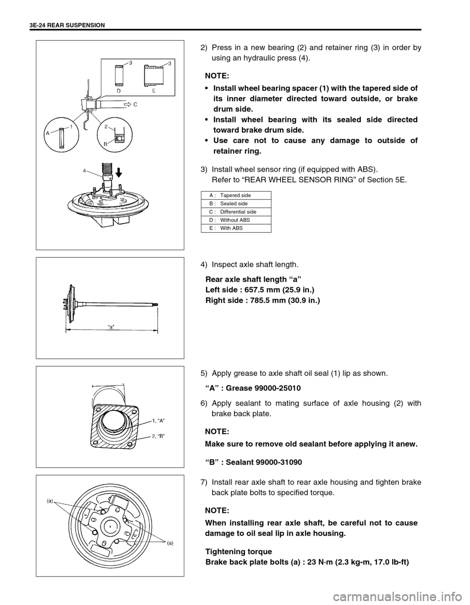
2) Press in a new bearing (2) and retainer ring (3) in order by
using an hydraulic press (4).
3) Install wheel sensor ring (if equipped with ABS).
Refer to “REAR WHEEL SENSOR RING” of Section 5E.
4) Inspect axle shaft length.
Rear axle shaft length “a”
Left side : 657.5 mm (25.9 in.)
Right side : 785.5 mm (30.9 in.)
5) Apply grease to axle shaft oil seal (1) lip as shown.
“A” : Grease 99000-25010
6) Apply sealant to mating surface of axle housing (2) with
brake back plate.
“B” : Sealant 99000-31090
7) Install rear axle shaft to rear axle housing and tighten brake
back plate bolts to specified torque.
Tightening torque
Brake back plate bolts (a) : 23 N·m (2.3 kg-m, 17.0 lb-ft) NOTE:
Install wheel bearing spacer (1) with the tapered side of
its inner diameter directed toward outside, or brake
drum side.
Install wheel bearing with its sealed side directed
toward brake drum side.
Use care not to cause any damage to outside of
retainer ring.
A : Tapered side
B : Sealed side
C : Differential side
D : Without ABS
E : With ABS
NOTE:
Make sure to remove old sealant before applying it anew.
NOTE:
When installing rear axle shaft, be careful not to cause
damage to oil seal lip in axle housing.
Page 278 of 698
BRAKES 5-5
DIAGNOSIS TABLE
Condition Possible Cause Correction
Not enough braking
forceBrake oil leakage from brake lines Locate leaking point and repair.
Brake disc or pads stained with oil Clean or replace.
Overheated brakes Determine cause and repair.
Poor contact of shoes on brake drum Repair for proper contact.
Brake shoes linings stained with oil or wet with
waterReplace.
Badly worn brake pad linings Replace.
Defective wheel cylinders Repair or replace.
Malfunctioning caliper assembly Repair or replace.
Air in system Bleed system.
Maladjusted sensor spring length of LSPV, if
equippedCheck or adjust.
Broken sensor spring of LSPV, if equipped Replace.
Defective LSPV, if equipped Replace.
Malfunctioning ABS (Antilock brake system), if
equippedCheck system and replace as nec-
essary.
Brake pull
(Brakes not working in
unison)Pad linings and/or shoe linings are wet with
water or stained with oil in some brakesReplace.
Drum-to-shoe clearance out of adjustment in
some brakes
(Malfunctioning auto adjusting mechanism)Check for inoperative auto adjust-
ing mechanism.
Disc and/or drum is out of round in some
brakesReplace.
Wheel tires are inflated unequally Inflate equally.
Malfunction in wheel cylinders Repair or replace.
Disturbed front end alignment Adjust as prescribed.
Unmatched tires on same axle Tires with approximately the same
amount of tread should be used on
the same axle.
Restricted brake pipes or hoses Check for soft hoses and damaged
lines. Replace with new hoses and
new double-walled steel brake tub-
ing.
Malfunctioning caliper assembly Check for stuck or sluggish pistons
and proper lubrication of caliper
slide bush.
Caliper should slide.
Loose suspension parts Check all suspension mountings.
Loose calipers Check and torque bolts to specifica-
tions.
Noise (high pitched
squeak without brake
applied)Front lining worn out Replace linings.
Contact wear indicator to brake disc Replace pads.
Rear brake locked pre-
maturelyMaladjusted sensor spring length of LSPV, if
equippedCheck or adjust.
Malfunction LSPV assembly, if equipped Replace assembly.