oil temperature SUZUKI SWIFT 2000 1.G RG413 Service User Guide
[x] Cancel search | Manufacturer: SUZUKI, Model Year: 2000, Model line: SWIFT, Model: SUZUKI SWIFT 2000 1.GPages: 698, PDF Size: 16.01 MB
Page 98 of 698
AIR CONDITIONING (OPTIONAL) 1B-33
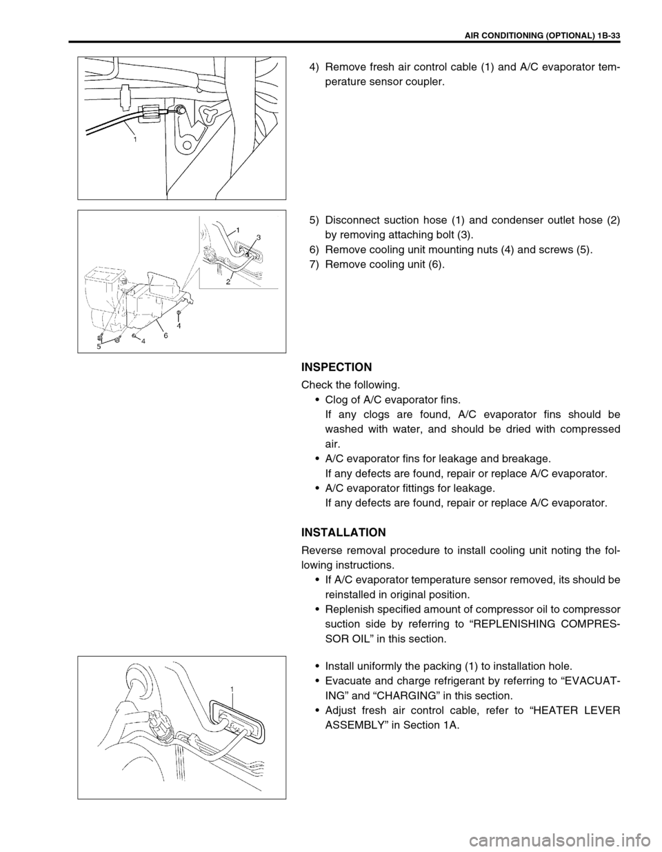
4) Remove fresh air control cable (1) and A/C evaporator tem-
perature sensor coupler.
5) Disconnect suction hose (1) and condenser outlet hose (2)
by removing attaching bolt (3).
6) Remove cooling unit mounting nuts (4) and screws (5).
7) Remove cooling unit (6).
INSPECTION
Check the following.
Clog of A/C evaporator fins.
If any clogs are found, A/C evaporator fins should be
washed with water, and should be dried with compressed
air.
A/C evaporator fins for leakage and breakage.
If any defects are found, repair or replace A/C evaporator.
A/C evaporator fittings for leakage.
If any defects are found, repair or replace A/C evaporator.
INSTALLATION
Reverse removal procedure to install cooling unit noting the fol-
lowing instructions.
If A/C evaporator temperature sensor removed, its should be
reinstalled in original position.
Replenish specified amount of compressor oil to compressor
suction side by referring to “REPLENISHING COMPRES-
SOR OIL” in this section.
Install uniformly the packing (1) to installation hole.
Evacuate and charge refrigerant by referring to “EVACUAT-
ING” and “CHARGING” in this section.
Adjust fresh air control cable, refer to “HEATER LEVER
ASSEMBLY” in Section 1A.
Page 99 of 698
1B-34 AIR CONDITIONING (OPTIONAL)
A/C EVAPORATOR TEMPERATURE SENSOR
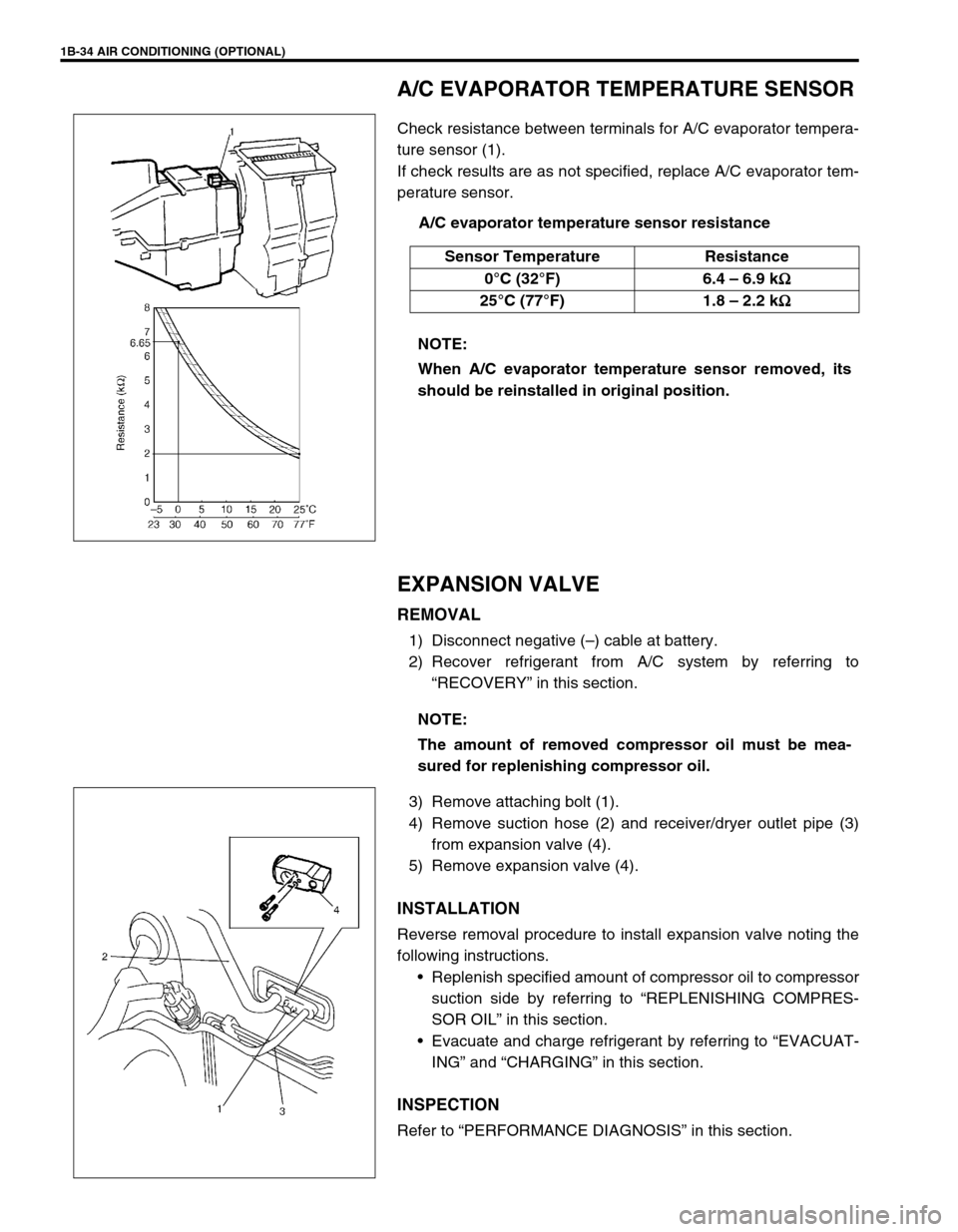
Check resistance between terminals for A/C evaporator tempera-
ture sensor (1).
If check results are as not specified, replace A/C evaporator tem-
perature sensor.
A/C evaporator temperature sensor resistance
EXPANSION VALVE
REMOVAL
1) Disconnect negative (–) cable at battery.
2) Recover refrigerant from A/C system by referring to
“RECOVERY” in this section.
3) Remove attaching bolt (1).
4) Remove suction hose (2) and receiver/dryer outlet pipe (3)
from expansion valve (4).
5) Remove expansion valve (4).
INSTALLATION
Reverse removal procedure to install expansion valve noting the
following instructions.
Replenish specified amount of compressor oil to compressor
suction side by referring to “REPLENISHING COMPRES-
SOR OIL” in this section.
Evacuate and charge refrigerant by referring to “EVACUAT-
ING” and “CHARGING” in this section.
INSPECTION
Refer to “PERFORMANCE DIAGNOSIS” in this section. Sensor Temperature Resistance
0°C (32°F) 6.4 – 6.9 k
Ω
ΩΩ Ω
25°C (77°F) 1.8 – 2.2 k
Ω
ΩΩ Ω
NOTE:
When A/C evaporator temperature sensor removed, its
should be reinstalled in original position.
NOTE:
The amount of removed compressor oil must be mea-
sured for replenishing compressor oil.
Page 399 of 698
6-30 ENGINE GENERAL INFORMATION AND DIAGNOSIS
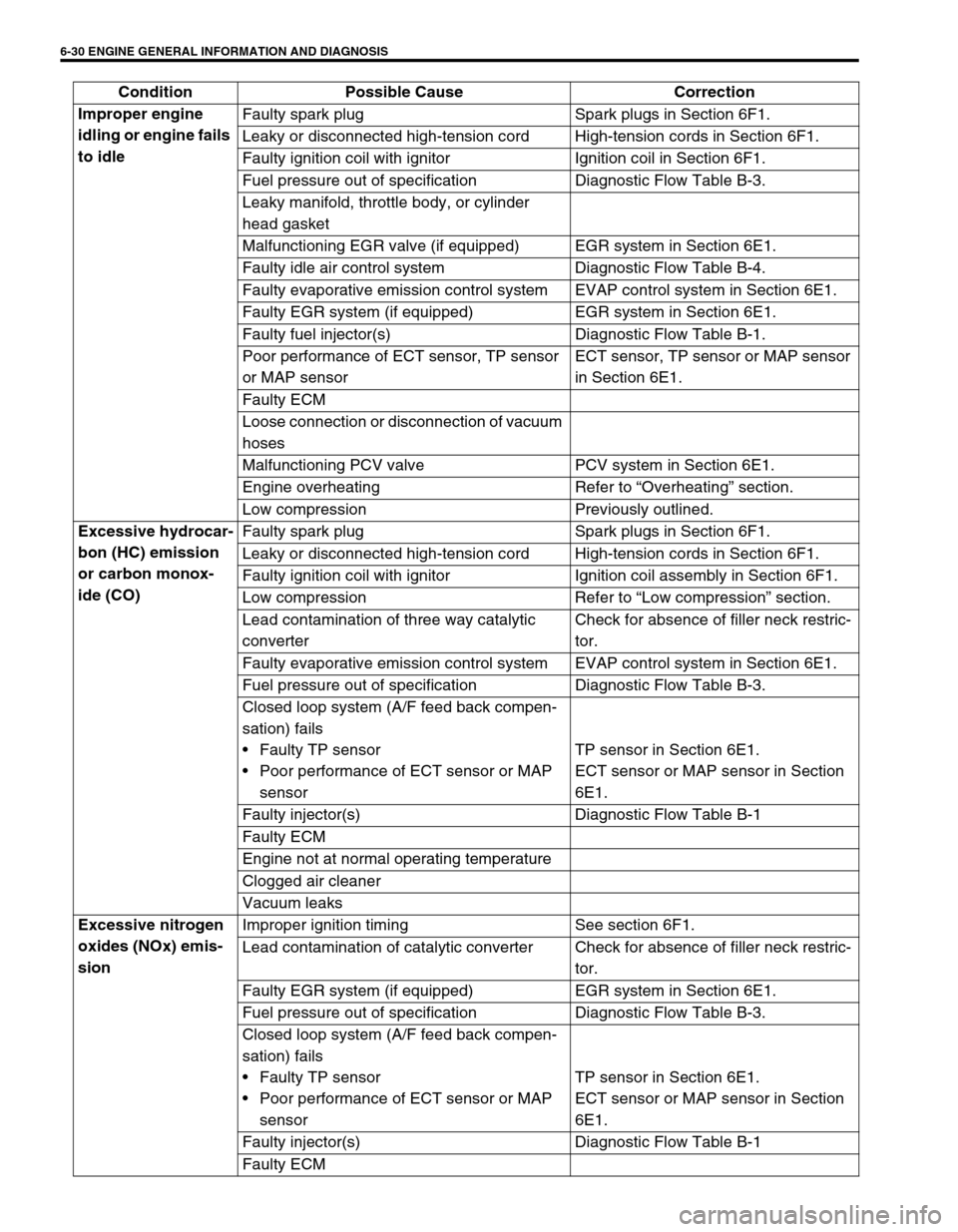
Improper engine
idling or engine fails
to idleFaulty spark plug Spark plugs in Section 6F1.
Leaky or disconnected high-tension cord High-tension cords in Section 6F1.
Faulty ignition coil with ignitor Ignition coil in Section 6F1.
Fuel pressure out of specification Diagnostic Flow Table B-3.
Leaky manifold, throttle body, or cylinder
head gasket
Malfunctioning EGR valve (if equipped) EGR system in Section 6E1.
Faulty idle air control system Diagnostic Flow Table B-4.
Faulty evaporative emission control system EVAP control system in Section 6E1.
Faulty EGR system (if equipped) EGR system in Section 6E1.
Faulty fuel injector(s) Diagnostic Flow Table B-1.
Poor performance of ECT sensor, TP sensor
or MAP sensorECT sensor, TP sensor or MAP sensor
in Section 6E1.
Faulty ECM
Loose connection or disconnection of vacuum
hoses
Malfunctioning PCV valve PCV system in Section 6E1.
Engine overheating Refer to “Overheating” section.
Low compression Previously outlined.
Excessive hydrocar-
bon (HC) emission
or carbon monox-
ide (CO)Faulty spark plug Spark plugs in Section 6F1.
Leaky or disconnected high-tension cord High-tension cords in Section 6F1.
Faulty ignition coil with ignitor Ignition coil assembly in Section 6F1.
Low compression Refer to “Low compression” section.
Lead contamination of three way catalytic
converterCheck for absence of filler neck restric-
tor.
Faulty evaporative emission control system EVAP control system in Section 6E1.
Fuel pressure out of specification Diagnostic Flow Table B-3.
Closed loop system (A/F feed back compen-
sation) fails
Faulty TP sensor
Poor performance of ECT sensor or MAP
sensorTP sensor in Section 6E1.
ECT sensor or MAP sensor in Section
6E1.
Faulty injector(s) Diagnostic Flow Table B-1
Faulty ECM
Engine not at normal operating temperature
Clogged air cleaner
Vacuum leaks
Excessive nitrogen
oxides (NOx) emis-
sionImproper ignition timing See section 6F1.
Lead contamination of catalytic converter Check for absence of filler neck restric-
tor.
Faulty EGR system (if equipped) EGR system in Section 6E1.
Fuel pressure out of specification Diagnostic Flow Table B-3.
Closed loop system (A/F feed back compen-
sation) fails
Faulty TP sensor
Poor performance of ECT sensor or MAP
sensorTP sensor in Section 6E1.
ECT sensor or MAP sensor in Section
6E1.
Faulty injector(s) Diagnostic Flow Table B-1
Faulty ECM Condition Possible Cause Correction
Page 412 of 698
ENGINE GENERAL INFORMATION AND DIAGNOSIS 6-43
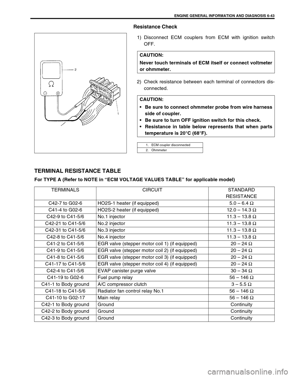
Resistance Check
1) Disconnect ECM couplers from ECM with ignition switch
OFF.
2) Check resistance between each terminal of connectors dis-
connected.
TERMINAL RESISTANCE TABLE
For TYPE A (Refer to NOTE in “ECM VOLTAGE VALUES TABLE” for applicable model) CAUTION:
Never touch terminals of ECM itself or connect voltmeter
or ohmmeter.
CAUTION:
Be sure to connect ohmmeter probe from wire harness
side of coupler.
Be sure to turn OFF ignition switch for this check.
Resistance in table below represents that when parts
temperature is 20°C (68°F).
1. ECM coupler disconnected
2. Ohmmeter
TERMINALS CIRCUIT STANDARD
RESISTANCE
C42-7 to G02-6 HO2S-1 heater (if equipped) 5.0 – 6.4 Ω
C41-4 to G02-6 HO2S-2 heater (if equipped) 12.0 – 14.3 Ω
C42-9 to C41-5/6 No.1 injector 11.3 – 13.8 Ω
C42-21 to C41-5/6 No.2 injector 11.3 – 13.8 Ω
C42-31 to C41-5/6 No.3 injector 11.3 – 13.8 Ω
C42-8 to C41-5/6 No.4 injector 11.3 – 13.8 Ω
C41-2 to C41-5/6 EGR valve (stepper motor coil 1) (if equipped) 20 – 24 Ω
C41-9 to C41-5/6 EGR valve (stepper motor coil 2) (if equipped) 20 – 24 Ω
C41-8 to C41-5/6 EGR valve (stepper motor coil 3) (if equipped) 20 – 24 Ω
C41-17 to C41-5/6 EGR valve (stepper motor coil 4) (if equipped) 20 – 24 Ω
C42-4 to C41-5/6 EVAP canister purge valve 30 – 34 Ω
C41-19 to G02-6 Fuel pump relay 56 – 146 Ω
C41-1 to Body ground A/C compressor clutch 3 – 5.5 Ω
C41-18 to C41-5/6 Radiator fan control relay No.1 56 – 146 Ω
C41-10 to G02-17 Main relay 56 – 146 Ω
C42-1 to Body ground Ground Continuity
C42-2 to Body ground Ground Continuity
C42-3 to Body ground Ground Continuity
Page 505 of 698

6A1-4 ENGINE MECHANICAL (M13 ENGINE)
DIAGNOSIS
DIAGNOSIS TABLE
Refer to “ENGINE MECHANICAL DIAGNOSIS TABLE” in Sec-
tion 6.
COMPRESSION CHECK
Check compression pressure on all 4 cylinders as follows:
1) Warm up engine to normal operating temperature.
2) Stop engine after warming up.
3) Remove air cleaner assembly (1), resonator (2) and hoses.
Refer to “AIR CLEANER ASSEMBLY AND RESONATOR”.
4) Remove cylinder head upper cover (1).
5) Disconnect ignition coil couplers (1).
6) Remove ignition coil assemblies (2) with high-tension cord
(3).
7) Remove all spark plugs.
8) Disconnect fuel injector wires (4) at the coupler.NOTE:
After warming up engine, place transmission gear shift
lever in “Neutral” (shift selector lever to “P” range for A/T
model), and set parking brake and block drive wheels.
Page 507 of 698
6A1-6 ENGINE MECHANICAL (M13 ENGINE)
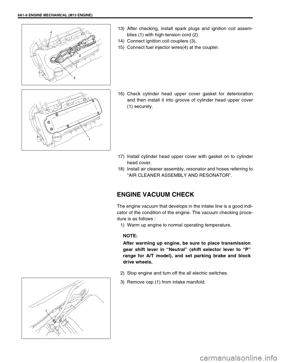
13) After checking, install spark plugs and ignition coil assem-
blies (1) with high-tension cord (2).
14) Connect ignition coil couplers (3).
15) Connect fuel injector wires(4) at the coupler.
16) Check cylinder head upper cover gasket for deterioration
and then install it into groove of cylinder head upper cover
(1) securely.
17) Install cylinder head upper cover with gasket on to cylinder
head cover.
18) Install air cleaner assembly, resonator and hoses referring to
“AIR CLEANER ASSEMBLY AND RESONATOR”.
ENGINE VACUUM CHECK
The engine vacuum that develops in the intake line is a good indi-
cator of the condition of the engine. The vacuum checking proce-
dure is as follows :
1) Warm up engine to normal operating temperature.
2) Stop engine and turn off the all electric switches.
3) Remove cap (1) from intake manifold.
NOTE:
After warming up engine, be sure to place transmission
gear shift lever in “Neutral” (shift selector lever to “P”
range for A/T model), and set parking brake and block
drive wheels.
Page 592 of 698
ENGINE COOLING 6B-3
COOLANT
The coolant recovery system is standard. The coolant in the radiator expands with heat, and the overflow is col-
lected in the reservoir.
When the system cools down, the coolant is drawn back into the radiator.
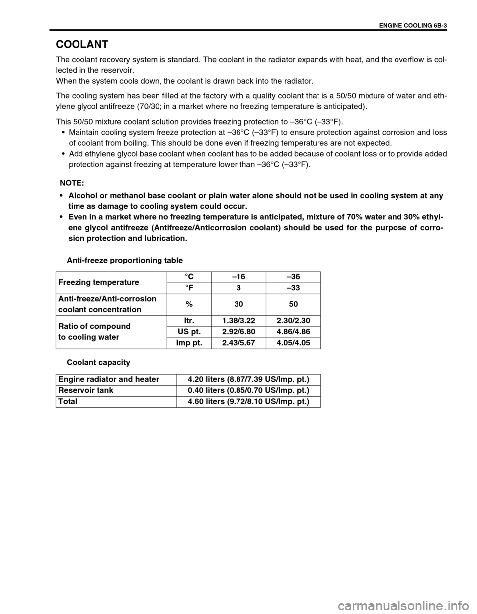
The cooling system has been filled at the factory with a quality coolant that is a 50/50 mixture of water and eth-
ylene glycol antifreeze (70/30; in a market where no freezing temperature is anticipated).
This 50/50 mixture coolant solution provides freezing protection to –36°C (–33°F).
Maintain cooling system freeze protection at –36°C (–33°F) to ensure protection against corrosion and loss
of coolant from boiling. This should be done even if freezing temperatures are not expected.
Add ethylene glycol base coolant when coolant has to be added because of coolant loss or to provide added
protection against freezing at temperature lower than –36°C (–33°F).
Anti-freeze proportioning table
Coolant capacity NOTE:
Alcohol or methanol base coolant or plain water alone should not be used in cooling system at any
time as damage to cooling system could occur.
Even in a market where no freezing temperature is anticipated, mixture of 70% water and 30% ethyl-
ene glycol antifreeze (Antifreeze/Anticorrosion coolant) should be used for the purpose of corro-
sion protection and lubrication.
Freezing temperature°C–16–36
°F3–33
Anti-freeze/Anti-corrosion
coolant concentration%30 50
Ratio of compound
to cooling waterItr. 1.38/3.22 2.30/2.30
US pt. 2.92/6.80 4.86/4.86
Imp pt. 2.43/5.67 4.05/4.05
Engine radiator and heater 4.20 liters (8.87/7.39 US/lmp. pt.)
Reservoir tank 0.40 liters (0.85/0.70 US/lmp. pt.)
Total 4.60 liters (9.72/8.10 US/lmp. pt.)
Page 595 of 698
6B-6 ENGINE COOLING
MAINTENANCE
COOLANT LEVEL CHECK
To check level, lift hood and look at “see-through” coolant reser-
voir tank.
It is not necessary to remove radiator cap to check coolant level.
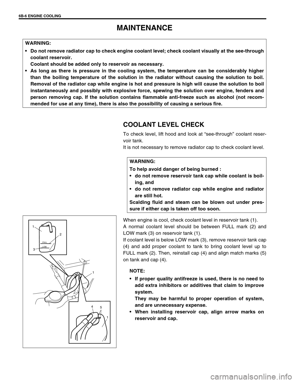
When engine is cool, check coolant level in reservoir tank (1).
A normal coolant level should be between FULL mark (2) and
LOW mark (3) on reservoir tank (1).
If coolant level is below LOW mark (3), remove reservoir tank cap
(4) and add proper coolant to tank to bring coolant level up to
FULL mark (2). Then, reinstall cap (4) and align match marks (5)
on tank and cap (4). WARNING:
Do not remove radiator cap to check engine coolant level; check coolant visually at the see-through
coolant reservoir.
Coolant should be added only to reservoir as necessary.
As long as there is pressure in the cooling system, the temperature can be considerably higher
than the boiling temperature of the solution in the radiator without causing the solution to boil.
Removal of the radiator cap while engine is hot and pressure is high will cause the solution to boil
instantaneously and possibly with explosive force, spewing the solution over engine, fenders and
person removing cap. If the solution contains flammable anti-freeze such as alcohol (not recom-
mended for use at any time), there is also the possibility of causing a serious fire.
WARNING:
To help avoid danger of being burned :
do not remove reservoir tank cap while coolant is boil-
ing, and
do not remove radiator cap while engine and radiator
are still hot.
Scalding fluid and steam can be blown out under pres-
sure if either cap is taken off too soon.
NOTE:
If proper quality antifreeze is used, there is no need to
add extra inhibitors or additives that claim to improve
system.
They may be harmful to proper operation of system,
and are unnecessary expense.
When installing reservoir cap, align arrow marks on
reservoir and cap.
LOW FULL
5 41
1 32 1
Page 688 of 698
6H-8 CHARGING SYSTEM
3) Ground F terminal and start engine, then measure voltage at
B terminal as shown in left figure.
Voltage is higher than standard value
It is considered that generator itself is good but IC regulator
has been damaged, replace IC regulator.
Voltage is lower than standard value
Generator itself has problem, check the generator.
LOAD CHECK
1) Run engine at 2,000 rpm and turn on head light and heater
motor.
2) Measure current and if it is less than 20 A repair or replace
generator.
OVERCHARGED BATTERY
1) To determine battery condition, refer to Battery section.
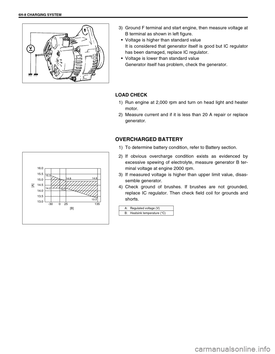
2) If obvious overcharge condition exists as evidenced by
excessive spewing of electrolyte, measure generator B ter-
minal voltage at engine 2000 rpm.
3) If measured voltage is higher than upper limit value, disas-
semble generator.
4) Check ground of brushes. If brushes are not grounded,
replace IC regulator. Then check field coil for grounds and
shorts.
A: Regulated voltage (V)
B: Heatsink temperature (°C)
16.0
15.5
14.2 15.3
14.8
14.2
13.314.8
15.0
14.5
14.0
13.5
13.0
-30 0 25 135
[A]
[B]