brakes SUZUKI SWIFT 2000 1.G RG413 Service Workshop Manual
[x] Cancel search | Manufacturer: SUZUKI, Model Year: 2000, Model line: SWIFT, Model: SUZUKI SWIFT 2000 1.GPages: 698, PDF Size: 16.01 MB
Page 3 of 698
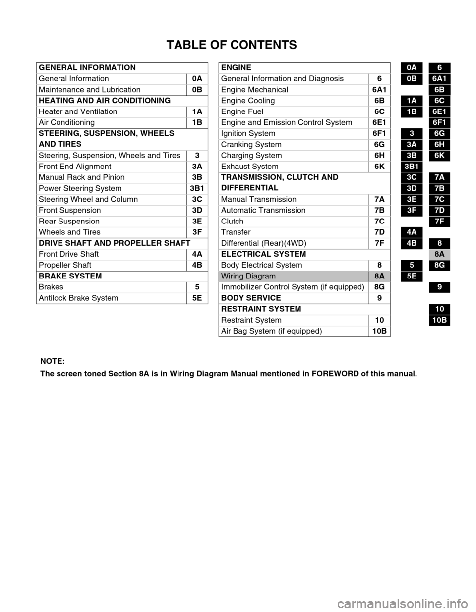
TABLE OF CONTENTS
GENERAL INFORMATION ENGINE0A6
General Information0A
General Information and Diagnosis6
0B6A1
Maintenance and Lubrication0B
Engine Mechanical6A1
6B
HEATING AND AIR CONDITIONING
Engine Cooling6B
1A6C
Heater and Ventilation1A
Engine Fuel6C
1B6E1
Air Conditioning1B
Engine and Emission Control System6E1
6F1
STEERING, SUSPENSION, WHEELS
AND TIRESIgnition System6F1
36G
Cranking System6G
3A6H
Steering, Suspension, Wheels and Tires3
Charging System6H
3B6K
Front End Alignment3A
Exhaust System6K
3B1 6B
Manual Rack and Pinion3B TRANSMISSION, CLUTCH AND
DIFFERENTIAL
3C7A
Power Steering System3B1
3D7B
Steering Wheel and Column3C
Manual Transmission7A
3E7C
Front Suspension3D
Automatic Transmission7B
3F7D
Rear Suspension3E
Clutch7C
7F
Wheels and Tires3F
Transfer7D
4A
DRIVE SHAFT AND PROPELLER SHAFT
Differential (Rear)(4WD)7F
4B8
Front Drive Shaft 4A ELECTRICAL SYSTEM
8A
Propeller Shaft4B
Body Electrical System8
58G
BRAKE SYSTEM
Wiring Diagram8A5E
Brakes5
Immobilizer Control System (if equipped)8G
9
Antilock Brake System5E BODY SERVICE 9
RESTRAINT SYSTEM
10
Restraint System10
10B
Air Bag System (if equipped)10B
NOTE:
The screen toned Section 8A is in Wiring Diagram Manual mentioned in FOREWORD of this manual.
Page 42 of 698
MAINTENANCE AND LUBRICATION 0B-13
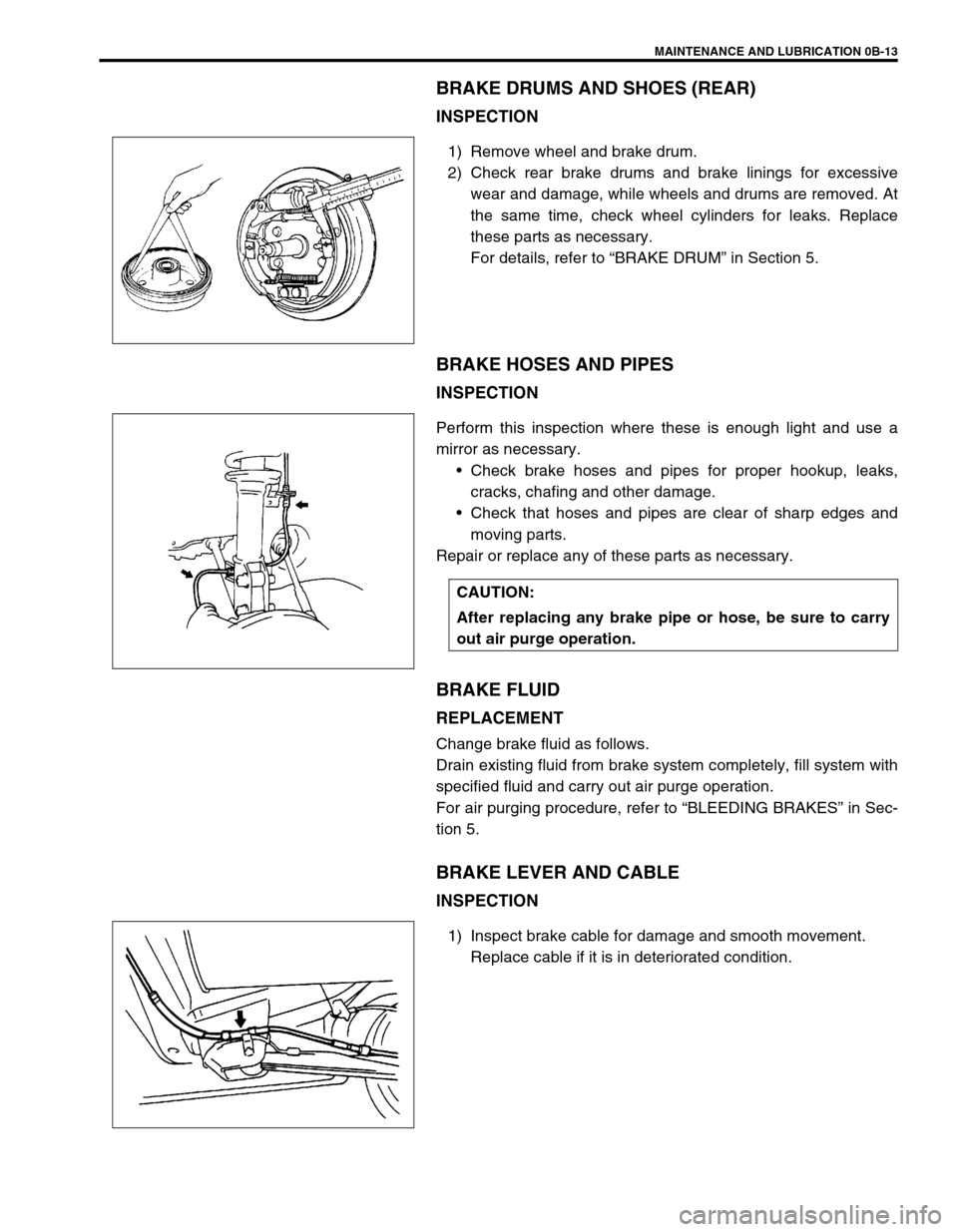
BRAKE DRUMS AND SHOES (REAR)
INSPECTION
1) Remove wheel and brake drum.
2) Check rear brake drums and brake linings for excessive
wear and damage, while wheels and drums are removed. At
the same time, check wheel cylinders for leaks. Replace
these parts as necessary.
For details, refer to “BRAKE DRUM” in Section 5.
BRAKE HOSES AND PIPES
INSPECTION
Perform this inspection where these is enough light and use a
mirror as necessary.
Check brake hoses and pipes for proper hookup, leaks,
cracks, chafing and other damage.
Check that hoses and pipes are clear of sharp edges and
moving parts.
Repair or replace any of these parts as necessary.
BRAKE FLUID
REPLACEMENT
Change brake fluid as follows.
Drain existing fluid from brake system completely, fill system with
specified fluid and carry out air purge operation.
For air purging procedure, refer to “BLEEDING BRAKES” in Sec-
tion 5.
BRAKE LEVER AND CABLE
INSPECTION
1) Inspect brake cable for damage and smooth movement.
Replace cable if it is in deteriorated condition.
CAUTION:
After replacing any brake pipe or hose, be sure to carry
out air purge operation.
Page 49 of 698
0B-20 MAINTENANCE AND LUBRICATION
ENGINE START
Check engine start for readiness.
On automatic transmission vehicles, try to start the engine in each select lever position. The starting motor
should crank only in “P” (Park) or “N” (Neutral).
On manual transmission vehicles, place the shift lever in “Neutral,” depress clutch pedal fully any try to start.
EXHAUST SYSTEM CHECK
Check for leakage, cracks or loose supports.
CLUTCH (FOR MANUAL TRANSMISSION)
Check for the following.
Clutch is completely released when depressing clutch pedal,
No slipping clutch occurs when releasing pedal and accelerating.
Clutch itself is free from any abnormal condition.
GEARSHIFT OR SELECT LEVER (TRANSMISSION)
Check gear shift or select lever for smooth shifting to all positions and for good performance of transmission in
any position.
With automatic transmission equipped vehicle, also check that shift indicator indicates properly according to
which position select lever is shifted to.
With automatic transmission equipped vehicle, make sure that vehicle is at complete stop when shifting select
lever to “P” range position and release all brakes.
BRAKE
Foot Brake
Check the followings:
that brake pedal has proper travel,
that brake works properly,
that it is free from noise,
that vehicle does not pull to one side when brake is applied.
and that brake do not drag.
Parking Brake
Check that lever has proper travel.
Check to ensure that parking brake is fully effective when the vehicle is stopped on the safe slope and brake
lever is pulled all the way.WARNING:
Before performing the following check, be sure to have enough room around the vehicle. Then, firmly
apply both the parking brake and the regular brakes. Do not use the accelerator pedal. If the engine
starts, be ready to turn off the ignition promptly. Take these precautions because the vehicle could
move without warning and possibly cause personal injury or property damage.
WARNING:
With vehicle parked on a fairly steep slope, make sure nothing is in the way downhill to avoid any per-
sonal injury or property damage. Be prepared to apply regular brake quickly even if vehicle should
start to move.
Page 113 of 698
3-4 STEERING, SUSPENSION, WHEELS AND TIRES
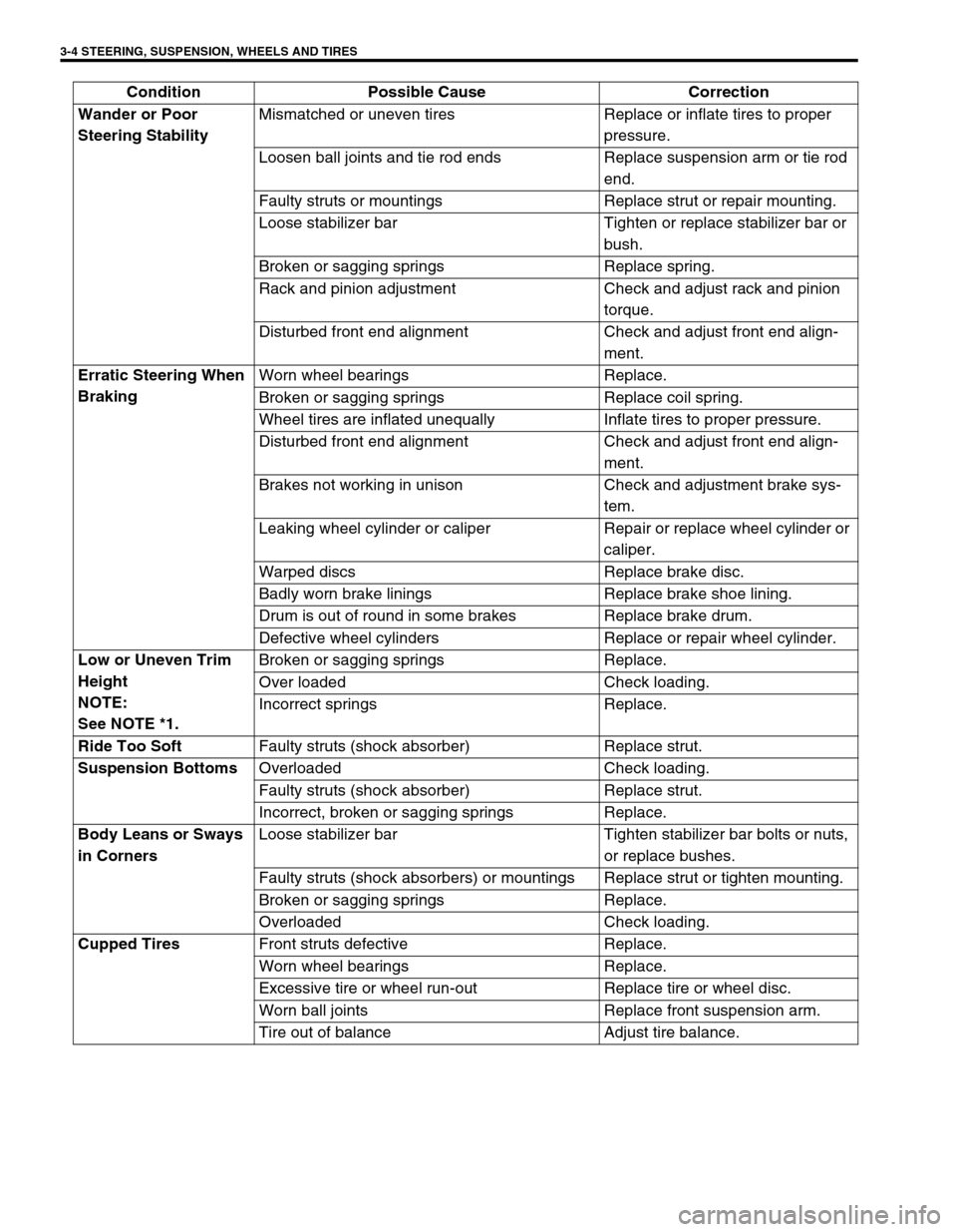
Wander or Poor
Steering StabilityMismatched or uneven tires Replace or inflate tires to proper
pressure.
Loosen ball joints and tie rod ends Replace suspension arm or tie rod
end.
Faulty struts or mountings Replace strut or repair mounting.
Loose stabilizer bar Tighten or replace stabilizer bar or
bush.
Broken or sagging springs Replace spring.
Rack and pinion adjustment Check and adjust rack and pinion
torque.
Disturbed front end alignment Check and adjust front end align-
ment.
Erratic Steering When
BrakingWorn wheel bearings Replace.
Broken or sagging springs Replace coil spring.
Wheel tires are inflated unequally Inflate tires to proper pressure.
Disturbed front end alignment Check and adjust front end align-
ment.
Brakes not working in unison Check and adjustment brake sys-
tem.
Leaking wheel cylinder or caliper Repair or replace wheel cylinder or
caliper.
Warped discs Replace brake disc.
Badly worn brake linings Replace brake shoe lining.
Drum is out of round in some brakes Replace brake drum.
Defective wheel cylinders Replace or repair wheel cylinder.
Low or Uneven Trim
Height
NOTE:
See NOTE *1.Broken or sagging springs Replace.
Over loaded Check loading.
Incorrect springs Replace.
Ride Too Soft
Faulty struts (shock absorber) Replace strut.
Suspension Bottoms
Overloaded Check loading.
Faulty struts (shock absorber) Replace strut.
Incorrect, broken or sagging springs Replace.
Body Leans or Sways
in CornersLoose stabilizer bar Tighten stabilizer bar bolts or nuts,
or replace bushes.
Faulty struts (shock absorbers) or mountings Replace strut or tighten mounting.
Broken or sagging springs Replace.
Overloaded Check loading.
Cupped Tires
Front struts defective Replace.
Worn wheel bearings Replace.
Excessive tire or wheel run-out Replace tire or wheel disc.
Worn ball joints Replace front suspension arm.
Tire out of balance Adjust tire balance. Condition Possible Cause Correction
Page 238 of 698
REAR SUSPENSION 3E-25
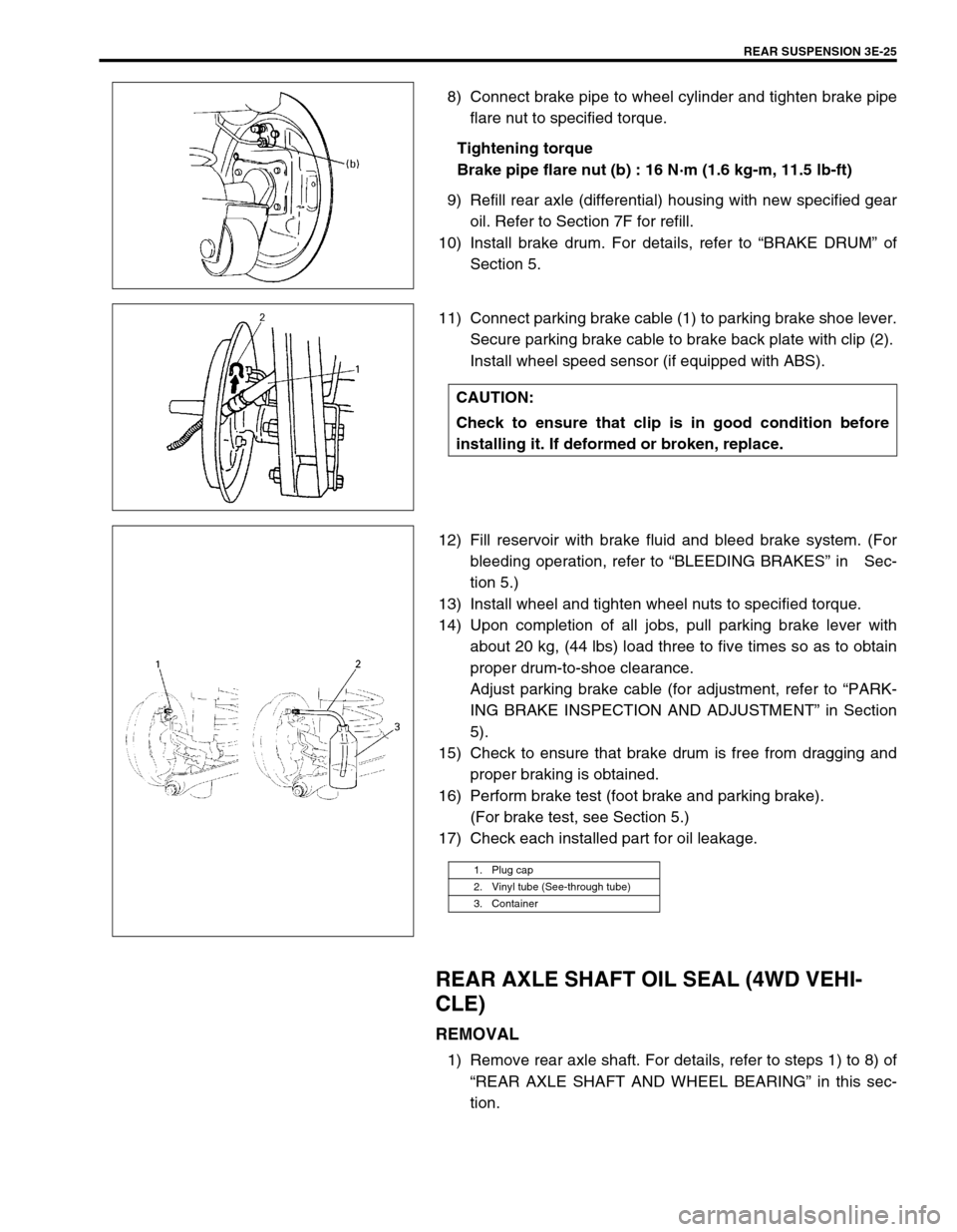
8) Connect brake pipe to wheel cylinder and tighten brake pipe
flare nut to specified torque.
Tightening torque
Brake pipe flare nut (b) : 16 N·m (1.6 kg-m, 11.5 lb-ft)
9) Refill rear axle (differential) housing with new specified gear
oil. Refer to Section 7F for refill.
10) Install brake drum. For details, refer to “BRAKE DRUM” of
Section 5.
11) Connect parking brake cable (1) to parking brake shoe lever.
Secure parking brake cable to brake back plate with clip (2).
Install wheel speed sensor (if equipped with ABS).
12) Fill reservoir with brake fluid and bleed brake system. (For
bleeding operation, refer to “BLEEDING BRAKES” in Sec-
tion 5.)
13) Install wheel and tighten wheel nuts to specified torque.
14) Upon completion of all jobs, pull parking brake lever with
about 20 kg, (44 lbs) load three to five times so as to obtain
proper drum-to-shoe clearance.
Adjust parking brake cable (for adjustment, refer to “PARK-
ING BRAKE INSPECTION AND ADJUSTMENT” in Section
5).
15) Check to ensure that brake drum is free from dragging and
proper braking is obtained.
16) Perform brake test (foot brake and parking brake).
(For brake test, see Section 5.)
17) Check each installed part for oil leakage.
REAR AXLE SHAFT OIL SEAL (4WD VEHI-
CLE)
REMOVAL
1) Remove rear axle shaft. For details, refer to steps 1) to 8) of
“REAR AXLE SHAFT AND WHEEL BEARING” in this sec-
tion.
CAUTION:
Check to ensure that clip is in good condition before
installing it. If deformed or broken, replace.
1. Plug cap
2. Vinyl tube (See-through tube)
3. Container
Page 274 of 698
BRAKES 5-1
6F1
6F2
6G
6H
6K
7A
7A1
7B1
7C1
7D
7E
7F
8A
8B
8C
5
9
10
10A
10B
SECTION 5
BRAKES
CONTENTS
GENERAL DESCRIPTION ................................ 5-2
DIAGNOSIS ....................................................... 5-4
ROAD TESTING BRAKES ............................. 5-4
BRAKE FLUID LEAKS ................................... 5-4
SUBSTANDARD OR CONTAMINATED
BRAKE FLUID ................................................ 5-4
DIAGNOSIS TABLE ....................................... 5-5
BRAKE PEDAL FREE HEIGHT
ADJUSTMENT ............................................... 5-8
BRAKE PEDAL PLAY INSPECTION ............. 5-8
STOP LIGHT SWITCH ADJUSTMENT.......... 5-8
EXCESSIVE PEDAL TRAVEL
INSPECTION ................................................. 5-9
FRONT BRAKE PAD INSPECTION .............. 5-9
BRAKE DISC INSPECTION........................... 5-9
PARKING BRAKE INSPECTION AND
ADJUSTMENT ............................................. 5-10
BOOSTER OPERATION INSPECTION....... 5-11
FLUID PRESSURE TEST (IF EQUIPPED
WITH LSPV) ................................................ 5-12
MASTER CYLINDER AND BRAKE FLUID
LEVEL INSPECTION ................................... 5-14
BRAKE HOSE AND PIPE INSPECTION ..... 5-15
HOSE ....................................................... 5-15
PIPE ......................................................... 5-15
ON-VEHICLE SERVICE .................................. 5-15AIR BLEEDING OF BRAKE SYSTEM ......... 5-15
FRONT BRAKE ........................................... 5-17
BRAKE PAD............................................. 5-17
CALIPER ASSEMBLY ............................. 5-19
BRAKE DISC ........................................... 5-23
REAR BRAKE .............................................. 5-25
BRAKE DRUM ......................................... 5-26
BRAKE SHOE .......................................... 5-29
WHEEL CYLINDER ................................. 5-30
BRAKE BACK PLATE (FOR 2WD
VEHICLE)................................................. 5-31
BRAKE BACK PLATE (FOR 4WD
VEHICLE)................................................. 5-33
MASTER CYLINDER ................................... 5-33
MASTER CYLINDER RESERVOIR ......... 5-33
MASTER CYLINDER ASSEMBLY........... 5-34
BRAKE BOOSTER ...................................... 5-38
BRAKE HOSE/PIPE .................................... 5-41
FRONT BRAKE HOSE/PIPE ................... 5-41
REAR BRAKE HOSE/PIPE...................... 5-44
PARKING BRAKE CABLE ........................... 5-46
LSPV (LOAD SENSING PROPORTIONING
VALVE) ASSEMBLY (IF EQUIPPED).......... 5-48
REQUIRED SERVICE MATERIAL.................. 5-50
SPECIAL TOOL .............................................. 5-50
NOTE:
All front fasteners are important attaching parts in that they could affect the performance of vital parts
and systems, and/or could result in major repair expense. They must be replaced with one of same
part number or with an equivalent part if replacement becomes necessary. Do not use a replacement
part of lesser quality or substitute design. Torque values must be used as specified during reassem-
bly to assure proper retention of all parts. There is to be no welding as it may result in extensive dam-
age and weakening of the metal.
Page 275 of 698
5-2 BRAKES
GENERAL DESCRIPTION
When the foot brake pedal is depressed, hydraulic pressure is developed in the master cylinder to actuate pis-
tons (two in front and four in rear).
The master cylinder is a tandem master cylinder. Brake pipes are connected to the master cylinder and they
make two independent circuits. One connects front right & rear left brakes and the other connects front left &
rear right brakes.
The load sensing proportioning valve (LSPV) or the proportioning valve (P valve) is included in these circuits
between the master cylinder and the rear brake for the vehicle without ABS.
In this brake system, the disc brake type is used for the front wheel brake and a drum brake type (leading/trailing
shoes) for the rear brake.
The parking brake system is mechanical. It applies brake force to only rear wheels by means of the cable and
mechanical linkage system. The same brake shoes are used for both parking and foot brakes.
Page 276 of 698
![SUZUKI SWIFT 2000 1.G RG413 Service Workshop Manual BRAKES 5-3
NOTE:
The figures shows left-hand steering vehicle.
[A] : For vehicle without ABS 3. Secondary side 7. LSPV (Load Sensing Proportioning valve)
[B] : For vehicle with ABS 4. Primary side 8. SUZUKI SWIFT 2000 1.G RG413 Service Workshop Manual BRAKES 5-3
NOTE:
The figures shows left-hand steering vehicle.
[A] : For vehicle without ABS 3. Secondary side 7. LSPV (Load Sensing Proportioning valve)
[B] : For vehicle with ABS 4. Primary side 8.](/img/20/7606/w960_7606-275.png)
BRAKES 5-3
NOTE:
The figures shows left-hand steering vehicle.
[A] : For vehicle without ABS 3. Secondary side 7. LSPV (Load Sensing Proportioning valve)
[B] : For vehicle with ABS 4. Primary side 8. P (Proportioning) valve
1. Brake booster 5. 4-way joint A: Forward
2. Master cylinder 6. ABS hydraulic unit/control module assembly
Page 277 of 698
5-4 BRAKES
DIAGNOSIS
ROAD TESTING BRAKES
Brakes should be tested on dry, clean, smooth and reasonably level roadway which is not crowned. Road test
brakes by making brake applications with both light and heavy pedal forces at various speeds to determine if the
vehicle stops evenly and effectively. Also drive vehicle to see if it leads to one side or the other without brake
application. If it does, check the tire pressure, front end alignment and front suspension attachments for loose-
ness. See diagnosis table for other causes.
BRAKE FLUID LEAKS
Check the master cylinder fluid levels. While a slight drop in reservoir level does result from normal lining wear,
an abnormally low level indicates a leak in the system. In such a case, check the entire brake system for leak-
age. If even a slight evidence of leakage is noted, the cause should be corrected or defective parts should be
replaced.
SUBSTANDARD OR CONTAMINATED BRAKE FLUID
Improper brake fluid, mineral oil or water in the fluid may cause the brake fluid to boil or the rubber components
in the hydraulic system to deteriorate.
If primary piston cups are swollen, then rubber parts have deteriorated. This deterioration may also be evi-
denced by swollen wheel cylinder piston cups on the drum brake wheels.
If deterioration of rubber is evident, disassemble all hydraulic parts and wash with alcohol. Dry these parts with
compressed air before assembly to keep alcohol out of the system. Replace all rubber parts in the system,
including hoses. Also, when working on the brake mechanisms, check for fluid on the linings.
If excessive fluid is found, replace the pads.
If master cylinder piston seals are satisfactory, check for leakage or excessive heat conditions. If leakage is not
found, drain fluid, flush with brake fluid, refill and bleed system.
The system must be flushed if there is any doubt as to the grade of fluid in the system or if fluid has been used
which contained parts that have been subjected to contaminated fluid.
Page 278 of 698
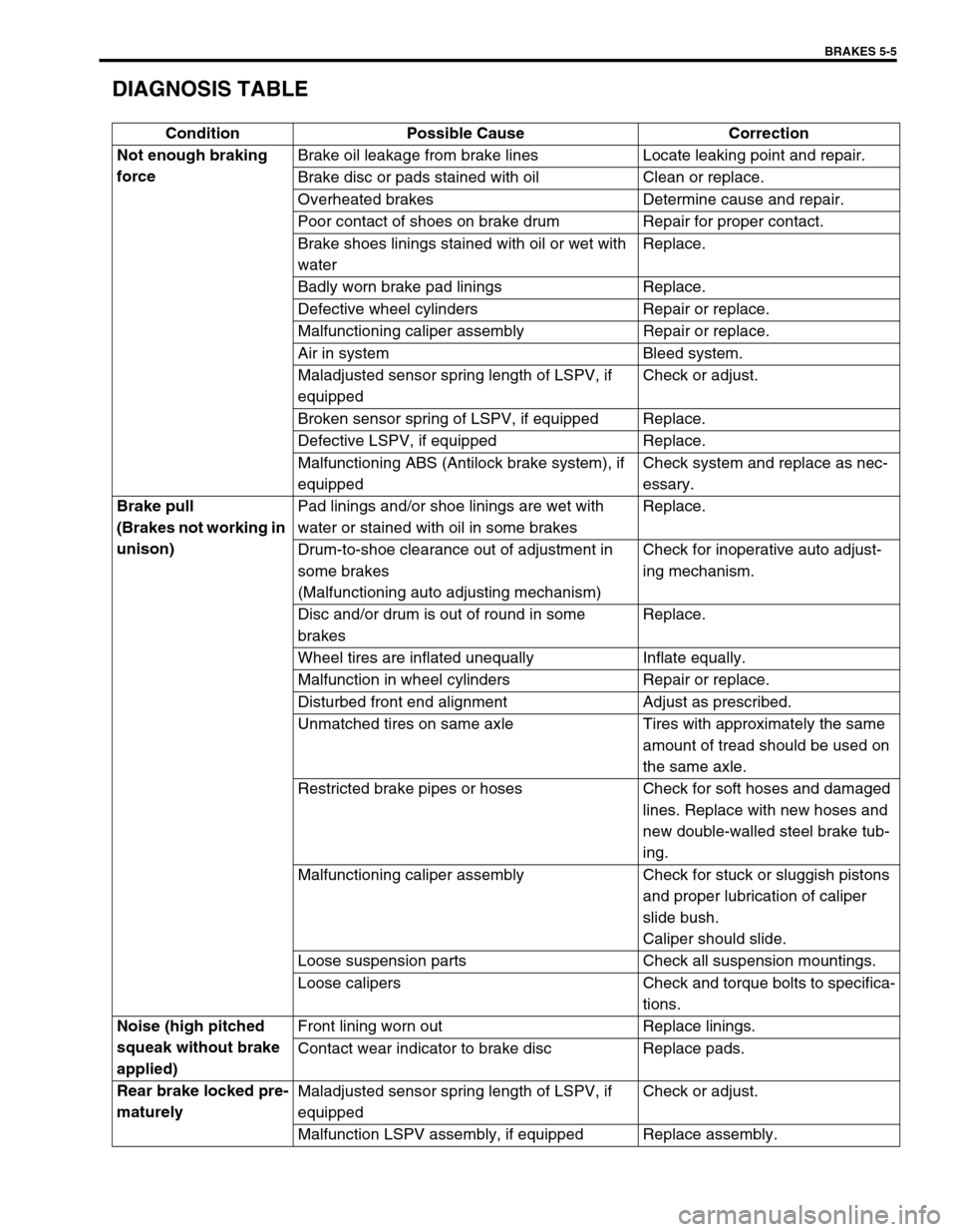
BRAKES 5-5
DIAGNOSIS TABLE
Condition Possible Cause Correction
Not enough braking
forceBrake oil leakage from brake lines Locate leaking point and repair.
Brake disc or pads stained with oil Clean or replace.
Overheated brakes Determine cause and repair.
Poor contact of shoes on brake drum Repair for proper contact.
Brake shoes linings stained with oil or wet with
waterReplace.
Badly worn brake pad linings Replace.
Defective wheel cylinders Repair or replace.
Malfunctioning caliper assembly Repair or replace.
Air in system Bleed system.
Maladjusted sensor spring length of LSPV, if
equippedCheck or adjust.
Broken sensor spring of LSPV, if equipped Replace.
Defective LSPV, if equipped Replace.
Malfunctioning ABS (Antilock brake system), if
equippedCheck system and replace as nec-
essary.
Brake pull
(Brakes not working in
unison)Pad linings and/or shoe linings are wet with
water or stained with oil in some brakesReplace.
Drum-to-shoe clearance out of adjustment in
some brakes
(Malfunctioning auto adjusting mechanism)Check for inoperative auto adjust-
ing mechanism.
Disc and/or drum is out of round in some
brakesReplace.
Wheel tires are inflated unequally Inflate equally.
Malfunction in wheel cylinders Repair or replace.
Disturbed front end alignment Adjust as prescribed.
Unmatched tires on same axle Tires with approximately the same
amount of tread should be used on
the same axle.
Restricted brake pipes or hoses Check for soft hoses and damaged
lines. Replace with new hoses and
new double-walled steel brake tub-
ing.
Malfunctioning caliper assembly Check for stuck or sluggish pistons
and proper lubrication of caliper
slide bush.
Caliper should slide.
Loose suspension parts Check all suspension mountings.
Loose calipers Check and torque bolts to specifica-
tions.
Noise (high pitched
squeak without brake
applied)Front lining worn out Replace linings.
Contact wear indicator to brake disc Replace pads.
Rear brake locked pre-
maturelyMaladjusted sensor spring length of LSPV, if
equippedCheck or adjust.
Malfunction LSPV assembly, if equipped Replace assembly.