tire SUZUKI SWIFT 2000 1.G RG413 Service User Guide
[x] Cancel search | Manufacturer: SUZUKI, Model Year: 2000, Model line: SWIFT, Model: SUZUKI SWIFT 2000 1.GPages: 698, PDF Size: 16.01 MB
Page 115 of 698
3-6 STEERING, SUSPENSION, WHEELS AND TIRES
RADIAL TIRE WADDLE
Waddle is side to side movement at the front and/or rear of the
vehicle. It is caused by the steel belt not being straight within the
tire. It is most noticeable at a low speed, 8 to 48 kph (5 to 30
mph).
It is possible to locate the faulty tire by road testing the vehicle. If
it is on the rear, the rear end of the vehicle shakes from side to
side or “waddles”. To the driver in the seat, it feels as though
someone is pushing on the side of vehicle.
If the faulty tire is on the front, waddling is more visual. The front
sheet metal appears to be moving back and forth and the driver
feels as though he is at the pivot point in vehicle.
Waddle can be quickly diagnosed by using Tire Problem Detector
(TPD) and following the equipment manufacture’s recommenda-
tions.
If TPD is not available, an alternative method of substituting
known-good tire/wheel assemblies can be used as follows,
although it takes a longer time.
1) Ride vehicle to determine whether the front or rear waddles.
2) Install tires and wheels that are known to be good (on similar vehicle) in place of those on waddling end of
vehicle. If waddling end cannot be identified, substitute rear ones.
3) Road test again. If improvement is noted, reinstall originals one at a time till waddle causal tire is found. If no
improvement is noted, install known-good tires in place of all four. Then reinstall originals in the same man-
ner as above.
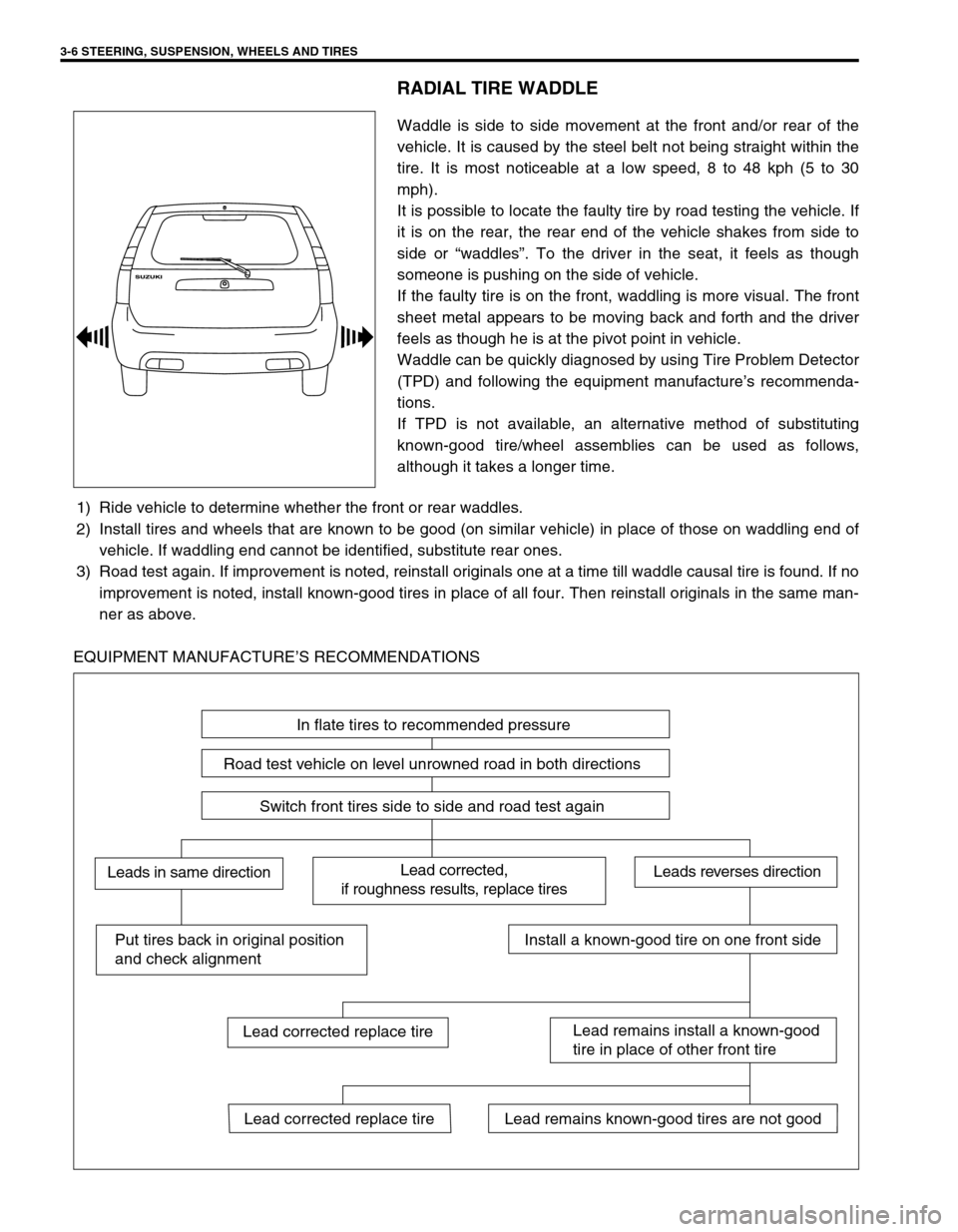
EQUIPMENT MANUFACTURE’S RECOMMENDATIONS
In flate tires to recommended pressure
Road test vehicle on level unrowned road in both directions
Switch front tires side to side and road test again
Lead corrected,
if roughness results, replace tiresLeads in same directionLeads reverses direction
Put tires back in original position
and check alignmentInstall a known-good tire on one front side
Lead remains install a known-good
tire in place of other front tire
Lead remains known-good tires are not goodLead corrected replace tire
Lead corrected replace tire
Page 116 of 698
STEERING, SUSPENSION, WHEELS AND TIRES 3-7
RADIAL TIRE LEAD
“Lead” is the deviation of the vehicle from a straight path on a level rod even with no pressure on the steering
wheel.
Lead is usually caused by:
Incorrect alignment.
Uneven brake adjustment.
Tire construction.
The way in which a tire is built can produce lead in a vehicle. An example of this is placement of the belt. Off
center belts on radial tires can cause the tire to develop a side force while rolling straight down the road. If one
side of the tire has a little larger diameter than the other, the tire will tend to roll to one side. This will develop a
side force which can produce vehicle lead.
The procedure in above figure (Lead Diagnosis) should be used to make sure that front alignment is not mis-
taken for tire lead.
Part of the lead diagnosis procedure is different from the proper tire rotation pattern currently in the owner
and service manuals. If a medium to high mileage tire is moved to the other side of the vehicle, be sure to
check that ride roughness has not developed
Rear tires will not cause lead.
VIBRATION DIAGNOSIS
Wheel unbalance causes most of the highway speed vibration problems. If a vibration remains after dynamic
balancing, its possible causes are as follows.
Tire runout.
Wheel runout.
Tire stiffness variation.
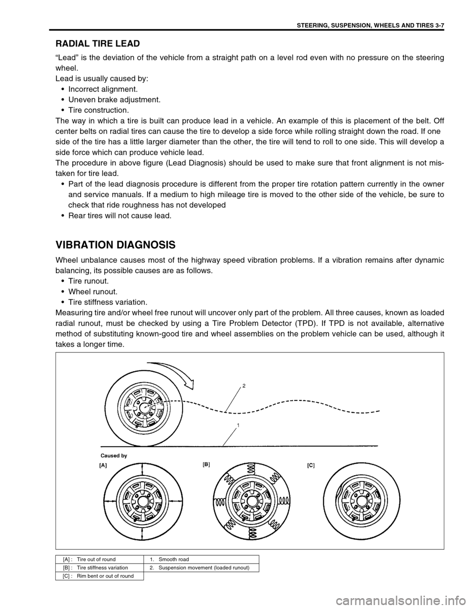
Measuring tire and/or wheel free runout will uncover only part of the problem. All three causes, known as loaded
radial runout, must be checked by using a Tire Problem Detector (TPD). If TPD is not available, alternative
method of substituting known-good tire and wheel assemblies on the problem vehicle can be used, although it
takes a longer time.
[A] : Tire out of round 1. Smooth road
[B] : Tire stiffness variation 2. Suspension movement (loaded runout)
[C] : Rim bent or out of round
Page 117 of 698

3-8 STEERING, SUSPENSION, WHEELS AND TIRES
Page 119 of 698
3A-2 FRONT END ALIGNMENT
GENERAL DESCRIPTION
Front alignment refers to the angular relationship between the
front wheels, the front suspension attaching parts and the ground.
Generally, the only adjustment required for front alignment is toe
setting.
Camber and caster can’t be adjusted. Therefore, should camber
or caster be out of specification due to the damage caused by
hazardous road conditions or collision, whether the damage is in
body or in suspension should be determined. If the body is dam-
aged, it should be repaired and if suspension is damaged, it
should be replaced.
TOE SETTING
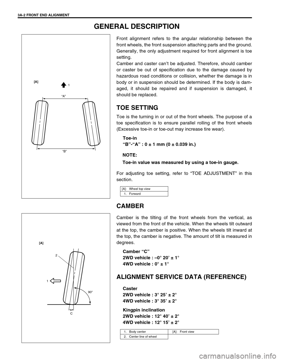
Toe is the turning in or out of the front wheels. The purpose of a
toe specification is to ensure parallel rolling of the front wheels
(Excessive toe-in or toe-out may increase tire wear).
Toe-in
“B”-“A” : 0 ± 1 mm (0 ± 0.039 in.)
For adjusting toe setting, refer to “TOE ADJUSTMENT” in this
section.
CAMBER
Camber is the tilting of the front wheels from the vertical, as
viewed from the front of the vehicle. When the wheels tilt outward
at the top, the camber is positive. When the wheels tilt inward at
the top, the camber is negative. The amount of tilt is measured in
degrees.
Camber “C”
2WD vehicle : –0° 20’ ± 1°
4WD vehicle : 0° ± 1°
ALIGNMENT SERVICE DATA (REFERENCE)
Caster
2WD vehicle : 3° 25’ ± 2°
4WD vehicle : 3° 35’ ± 2°
Kingpin inclination
2WD vehicle : 12° 40’ ± 2°
4WD vehicle : 12° 15’ ± 2° NOTE:
Toe-in value was measured by using a toe-in gauge.
[A]: Wheel top view
1. Forward
“A”
“B”1 [A]
1. Body center [A]: Front view
2. Center line of wheel
2
1
90
o
C [A]
Page 120 of 698
FRONT END ALIGNMENT 3A-3
DIAGNOSIS
DIAGNOSIS TABLE
For the details, refer to Section 3.
PRELIMINARY CHECKS PRIOR TO ADJUSTING FRONT ALIGNMENT
Steering and vibration complaints are not always the result of improper alignment. An additional item to be
checked is the possibility of tire lead due to worn or improperly manufactured tires. “Lead” is the deviation of the
vehicle from a straight path on a level road without hand pressure on the steering wheel. Procedure for deter-
mining the presence of a tire lead problem contains in SECTION 3. Before making any adjustment affecting toe
setting, the following checks and inspections should be made to ensure correctness of alignment readings and
alignment adjustments:
1) Check all tires for proper inflation pressures and approximately the same tread wear.
2) Check for loose of ball joints. Check tie rod ends; if excessive looseness is noted, it must be corrected
before adjusting.
3) Check for run-out of wheels and tires.
4) Check vehicle trim heights; if out of limits and a correction is to be made, it must be made before adjusting
toe.
5) Check for loose of suspension arms.
6) Check for loose or missing stabilizer bar attachments.
7) Consideration must be given to excess loads, such as tool boxes. If this excess load is normally carried in
vehicle, it should remain in vehicle during alignment checks.
8) Consider condition of equipment being used to check alignment and follow manufacturer's instructions.
9) Regardless of equipment used to check alignment, vehicle must be on a level surface both fore and aft and
transversely.
TOE ADJUSTMENT
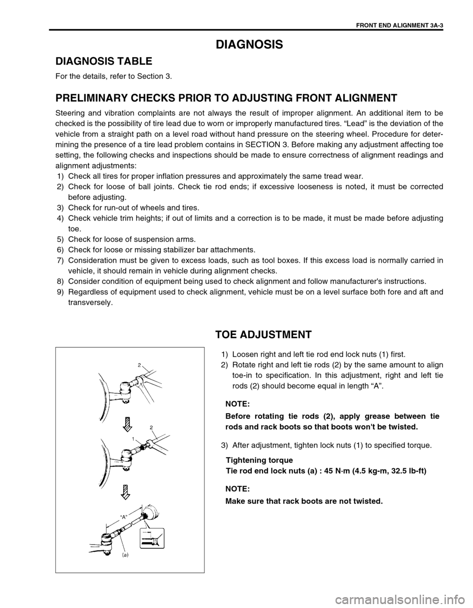
1) Loosen right and left tie rod end lock nuts (1) first.
2) Rotate right and left tie rods (2) by the same amount to align
toe-in to specification. In this adjustment, right and left tie
rods (2) should become equal in length “A”.
3) After adjustment, tighten lock nuts (1) to specified torque.
Tightening torque
Tie rod end lock nuts (a) : 45 N·m (4.5 kg-m, 32.5 lb-ft) NOTE:
Before rotating tie rods (2), apply grease between tie
rods and rack boots so that boots won't be twisted.
NOTE:
Make sure that rack boots are not twisted.
Page 137 of 698
3B-16 MANUAL RACK AND PINION
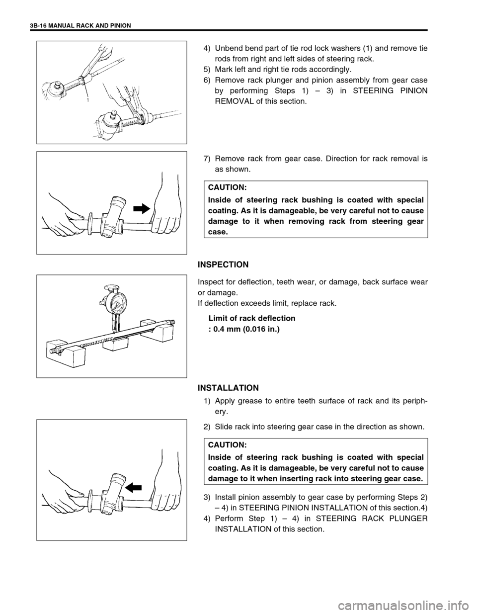
4) Unbend bend part of tie rod lock washers (1) and remove tie
rods from right and left sides of steering rack.
5) Mark left and right tie rods accordingly.
6) Remove rack plunger and pinion assembly from gear case
by performing Steps 1) – 3) in STEERING PINION
REMOVAL of this section.
7) Remove rack from gear case. Direction for rack removal is
as shown.
INSPECTION
Inspect for deflection, teeth wear, or damage, back surface wear
or damage.
If deflection exceeds limit, replace rack.
Limit of rack deflection
: 0.4 mm (0.016 in.)
INSTALLATION
1) Apply grease to entire teeth surface of rack and its periph-
ery.
2) Slide rack into steering gear case in the direction as shown.
3) Install pinion assembly to gear case by performing Steps 2)
– 4) in STEERING PINION INSTALLATION of this section.4)
4) Perform Step 1) – 4) in STEERING RACK PLUNGER
INSTALLATION of this section.
CAUTION:
Inside of steering rack bushing is coated with special
coating. As it is damageable, be very careful not to cause
damage to it when removing rack from steering gear
case.
CAUTION:
Inside of steering rack bushing is coated with special
coating. As it is damageable, be very careful not to cause
damage to it when inserting rack into steering gear case.
Page 140 of 698
MANUAL RACK AND PINION 3B-19
INSTALLATION
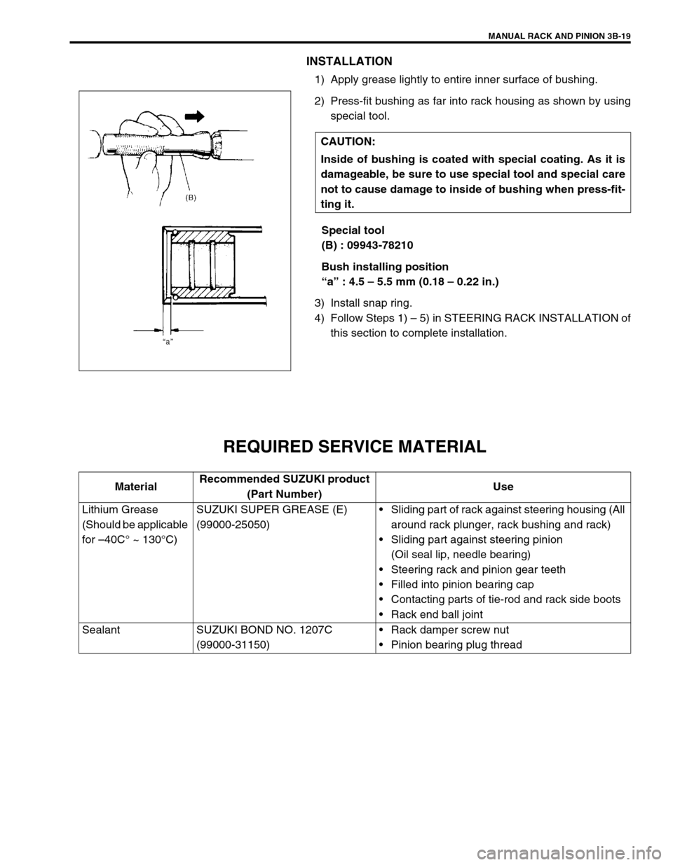
1) Apply grease lightly to entire inner surface of bushing.
2) Press-fit bushing as far into rack housing as shown by using
special tool.
Special tool
(B) : 09943-78210
Bush installing position
“a” : 4.5 – 5.5 mm (0.18 – 0.22 in.)
3) Install snap ring.
4) Follow Steps 1) – 5) in STEERING RACK INSTALLATION of
this section to complete installation.
REQUIRED SERVICE MATERIAL
CAUTION:
Inside of bushing is coated with special coating. As it is
damageable, be sure to use special tool and special care
not to cause damage to inside of bushing when press-fit-
ting it.
MaterialRecommended SUZUKI product
(Part Number)Use
Lithium Grease
(Should be applicable
for –40C° ~ 130°C)SUZUKI SUPER GREASE (E)
(99000-25050)Sliding part of rack against steering housing (All
around rack plunger, rack bushing and rack)
Sliding part against steering pinion
(Oil seal lip, needle bearing)
Steering rack and pinion gear teeth
Filled into pinion bearing cap
Contacting parts of tie-rod and rack side boots
Rack end ball joint
Sealant SUZUKI BOND NO. 1207C
(99000-31150)Rack damper screw nut
Pinion bearing plug thread
Page 160 of 698
ELECTRICAL POWER STEERING (P/S) SYSTEM 3B1-19
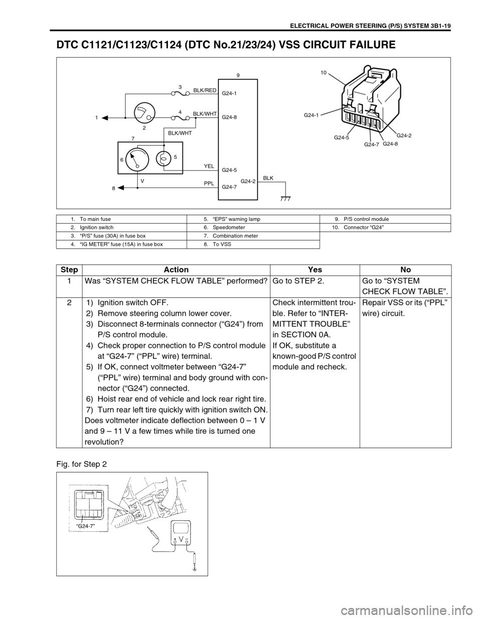
DTC C1121/C1123/C1124 (DTC No.21/23/24) VSS CIRCUIT FAILURE
Fig. for Step 2
1. To main fuse 5.“EPS” warning lamp 9. P/S control module
2. Ignition switch 6. Speedometer 10. Connector “G24”
3.“P/S” fuse (30A) in fuse box 7. Combination meter
4.“IG METER” fuse (15A) in fuse box 8. To VSS
G24-2 G24-1
G24-8
G24-7 G24-5 1
23
4
5
67
89
BLK/WHT
BLK/WHTBLK/RED
YEL
PPL VBLK
G24-1
G24-5
G24-7G24-8G24-2
10
Step Action Yes No
1Was “SYSTEM CHECK FLOW TABLE” performed? Go to STEP 2. Go to “SYSTEM
CHECK FLOW TABLE”.
2 1) Ignition switch OFF.
2) Remove steering column lower cover.
3) Disconnect 8-terminals connector (“G24”) from
P/S control module.
4) Check proper connection to P/S control module
at “G24-7” (“PPL” wire) terminal.
5) If OK, connect voltmeter between “G24-7”
(“PPL” wire) terminal and body ground with con-
nector (“G24”) connected.
6) Hoist rear end of vehicle and lock rear right tire.
7) Turn rear left tire quickly with ignition switch ON.
Does voltmeter indicate deflection between 0 – 1 V
and 9 – 11 V a few times while tire is turned one
revolution?Check intermittent trou-
ble. Refer to “INTER-
MITTENT TROUBLE”
in SECTION 0A.
If OK, substitute a
known-good P/S control
module and recheck.Repair VSS or its (“PPL”
wire) circuit.
Page 168 of 698
ELECTRICAL POWER STEERING (P/S) SYSTEM 3B1-27
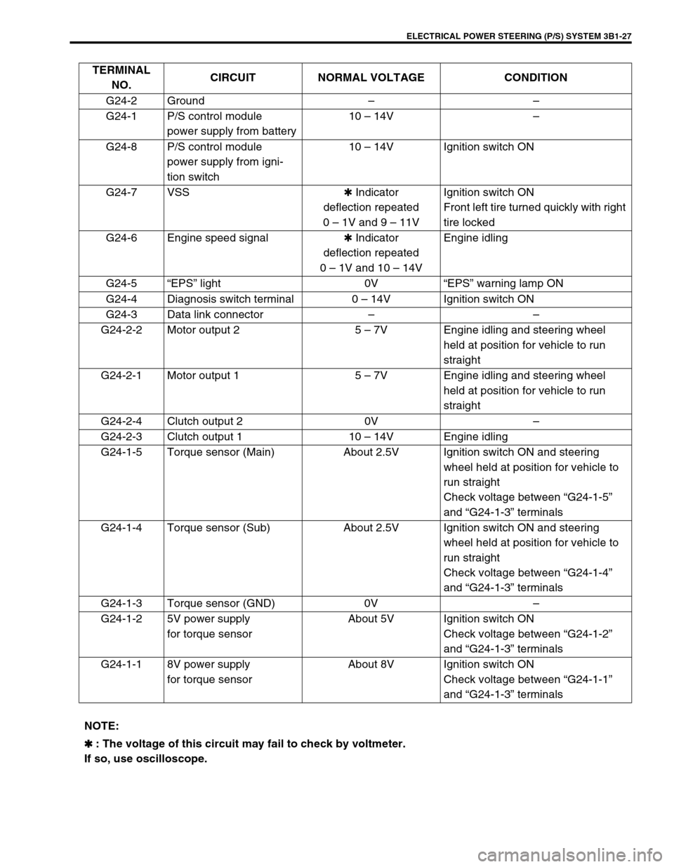
TERMINAL
NO.CIRCUIT NORMAL VOLTAGE CONDITION
G24-2 Ground––
G24-1 P/S control module
power supply from battery10 – 14V–
G24-8 P/S control module
power supply from igni-
tion switch10 – 14V Ignition switch ON
G24-7 VSS✱ Indicator
deflection repeated
0 – 1V and 9 – 11VIgnition switch ON
Front left tire turned quickly with right
tire locked
G24-6 Engine speed signal✱ Indicator
deflection repeated
0 – 1V and 10 – 14VEngine idling
G24-5“EPS” light 0V“EPS” warning lamp ON
G24-4 Diagnosis switch terminal 0 – 14V Ignition switch ON
G24-3 Data link connector––
G24-2-2 Motor output 2 5 – 7V Engine idling and steering wheel
held at position for vehicle to run
straight
G24-2-1 Motor output 1 5 – 7V Engine idling and steering wheel
held at position for vehicle to run
straight
G24-2-4 Clutch output 2 0V–
G24-2-3 Clutch output 1 10 – 14V Engine idling
G24-1-5 Torque sensor (Main) About 2.5V Ignition switch ON and steering
wheel held at position for vehicle to
run straight
Check voltage between “G24-1-5”
and “G24-1-3” terminals
G24-1-4 Torque sensor (Sub) About 2.5V Ignition switch ON and steering
wheel held at position for vehicle to
run straight
Check voltage between “G24-1-4”
and “G24-1-3” terminals
G24-1-3 Torque sensor (GND) 0V–
G24-1-2 5V power supply
for torque sensorAbout 5V Ignition switch ON
Check voltage between “G24-1-2”
and “G24-1-3” terminals
G24-1-1 8V power supply
for torque sensorAbout 8V Ignition switch ON
Check voltage between “G24-1-1”
and “G24-1-3” terminals
NOTE:
✱
✱✱ ✱ : The voltage of this circuit may fail to check by voltmeter.
If so, use oscilloscope.
Page 169 of 698
3B1-28 ELECTRICAL POWER STEERING (P/S) SYSTEM
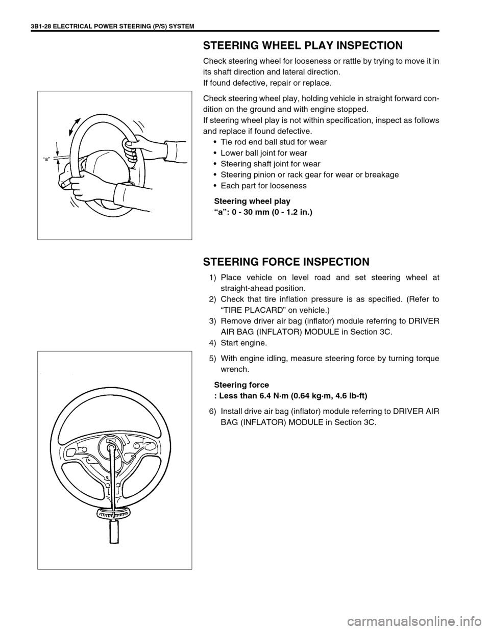
STEERING WHEEL PLAY INSPECTION
Check steering wheel for looseness or rattle by trying to move it in
its shaft direction and lateral direction.
If found defective, repair or replace.
Check steering wheel play, holding vehicle in straight forward con-
dition on the ground and with engine stopped.
If steering wheel play is not within specification, inspect as follows
and replace if found defective.
Tie rod end ball stud for wear
Lower ball joint for wear
Steering shaft joint for wear
Steering pinion or rack gear for wear or breakage
Each part for looseness
Steering wheel play
“a”: 0 - 30 mm (0 - 1.2 in.)
STEERING FORCE INSPECTION
1) Place vehicle on level road and set steering wheel at
straight-ahead position.
2) Check that tire inflation pressure is as specified. (Refer to
“TIRE PLACARD” on vehicle.)
3) Remove driver air bag (inflator) module referring to DRIVER
AIR BAG (INFLATOR) MODULE in Section 3C.
4) Start engine.
5) With engine idling, measure steering force by turning torque
wrench.
Steering force
: Less than 6.4 N·m (0.64 kg·m, 4.6 lb-ft)
6) Install drive air bag (inflator) module referring to DRIVER AIR
BAG (INFLATOR) MODULE in Section 3C.