transmission SUZUKI SWIFT 2000 1.G RG413 Service User Guide
[x] Cancel search | Manufacturer: SUZUKI, Model Year: 2000, Model line: SWIFT, Model: SUZUKI SWIFT 2000 1.GPages: 698, PDF Size: 16.01 MB
Page 46 of 698
MAINTENANCE AND LUBRICATION 0B-17
MANUAL TRANSMISSION OIL
INSPECTION
1) Inspect transmission case for evidence of oil leakage.
Repair leaky point if any.
2) Make sure that vehicle is placed level for oil level check.
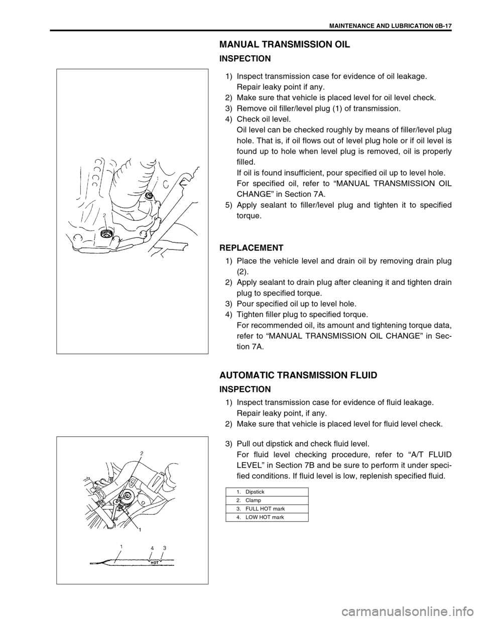
3) Remove oil filler/level plug (1) of transmission.
4) Check oil level.
Oil level can be checked roughly by means of filler/level plug
hole. That is, if oil flows out of level plug hole or if oil level is
found up to hole when level plug is removed, oil is properly
filled.
If oil is found insufficient, pour specified oil up to level hole.
For specified oil, refer to “MANUAL TRANSMISSION OIL
CHANGE” in Section 7A.
5) Apply sealant to filler/level plug and tighten it to specified
torque.
REPLACEMENT
1) Place the vehicle level and drain oil by removing drain plug
(2).
2) Apply sealant to drain plug after cleaning it and tighten drain
plug to specified torque.
3) Pour specified oil up to level hole.
4) Tighten filler plug to specified torque.
For recommended oil, its amount and tightening torque data,
refer to “MANUAL TRANSMISSION OIL CHANGE” in Sec-
tion 7A.
AUTOMATIC TRANSMISSION FLUID
INSPECTION
1) Inspect transmission case for evidence of fluid leakage.
Repair leaky point, if any.
2) Make sure that vehicle is placed level for fluid level check.
3) Pull out dipstick and check fluid level.
For fluid level checking procedure, refer to “A/T FLUID
LEVEL” in Section 7B and be sure to perform it under speci-
fied conditions. If fluid level is low, replenish specified fluid.
1. Dipstick
2. Clamp
3. FULL HOT mark
4. LOW HOT mark
Page 47 of 698
0B-18 MAINTENANCE AND LUBRICATION
REPLACEMENT
1) Inspect transmission case for evidence of fluid leakage.
Repair leaky point, if any.
2) Make sure that vehicle is placed level for fluid level check.
3) Change fluid. For its procedure, refer to “CHANGING A/T
FLUID” in Section 7B.
TRANSFER OIL (4WD) AND REAR DIFFERENTIAL
OIL (4WD)
INSPECTION
1) Check transfer case or differential for evidence of oil leak-
age.
Repair leaky point if any.
2) Make sure that vehicle is placed level for oil level check.
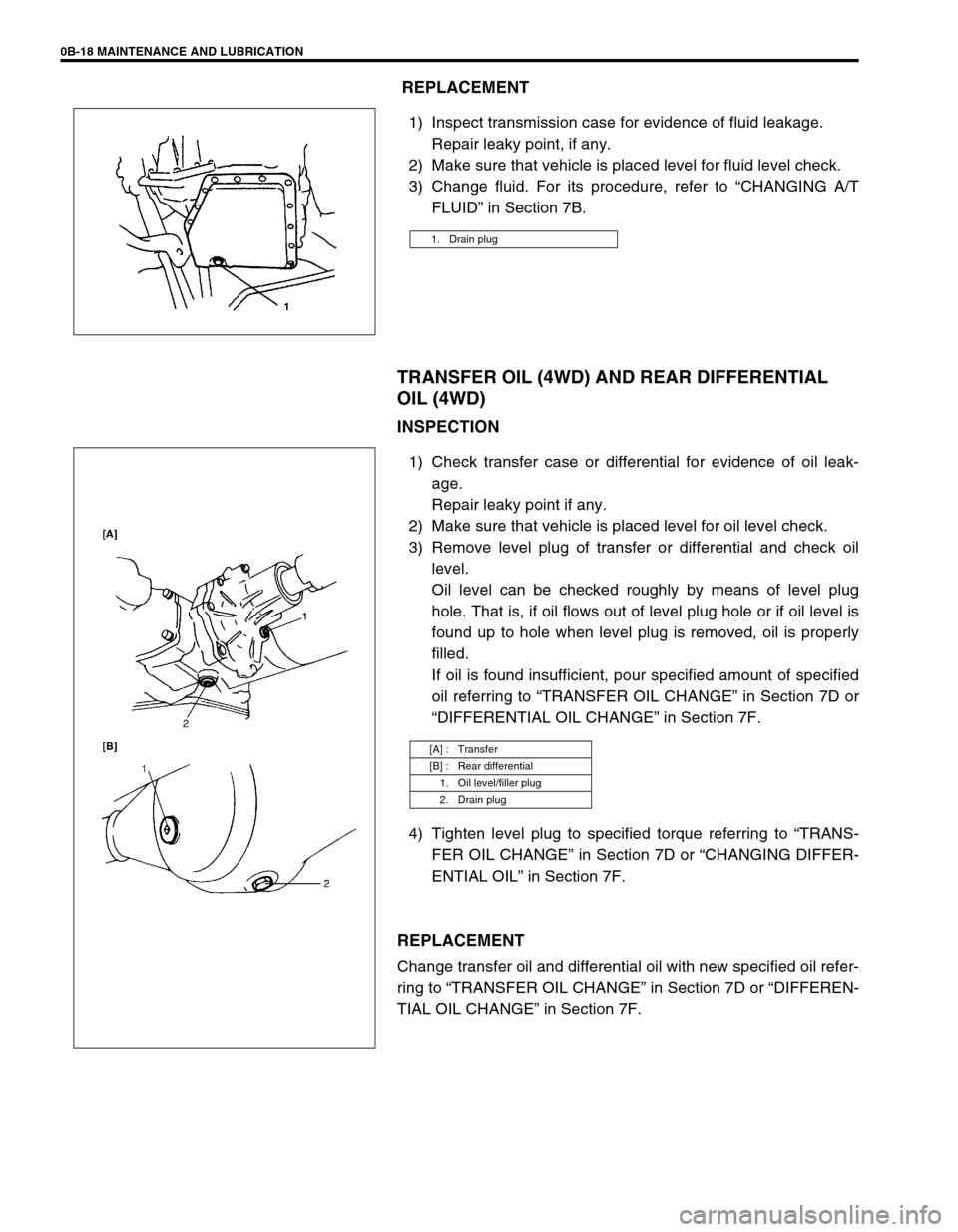
3) Remove level plug of transfer or differential and check oil
level.
Oil level can be checked roughly by means of level plug
hole. That is, if oil flows out of level plug hole or if oil level is
found up to hole when level plug is removed, oil is properly
filled.
If oil is found insufficient, pour specified amount of specified
oil referring to “TRANSFER OIL CHANGE” in Section 7D or
“DIFFERENTIAL OIL CHANGE” in Section 7F.
4) Tighten level plug to specified torque referring to “TRANS-
FER OIL CHANGE” in Section 7D or “CHANGING DIFFER-
ENTIAL OIL” in Section 7F.
REPLACEMENT
Change transfer oil and differential oil with new specified oil refer-
ring to “TRANSFER OIL CHANGE” in Section 7D or “DIFFEREN-
TIAL OIL CHANGE” in Section 7F.
1. Drain plug
[A] : Transfer
[B] : Rear differential
1. Oil level/filler plug
2. Drain plug
Page 49 of 698
0B-20 MAINTENANCE AND LUBRICATION
ENGINE START
Check engine start for readiness.
On automatic transmission vehicles, try to start the engine in each select lever position. The starting motor
should crank only in “P” (Park) or “N” (Neutral).
On manual transmission vehicles, place the shift lever in “Neutral,” depress clutch pedal fully any try to start.
EXHAUST SYSTEM CHECK
Check for leakage, cracks or loose supports.
CLUTCH (FOR MANUAL TRANSMISSION)
Check for the following.
Clutch is completely released when depressing clutch pedal,
No slipping clutch occurs when releasing pedal and accelerating.
Clutch itself is free from any abnormal condition.
GEARSHIFT OR SELECT LEVER (TRANSMISSION)
Check gear shift or select lever for smooth shifting to all positions and for good performance of transmission in
any position.
With automatic transmission equipped vehicle, also check that shift indicator indicates properly according to
which position select lever is shifted to.
With automatic transmission equipped vehicle, make sure that vehicle is at complete stop when shifting select
lever to “P” range position and release all brakes.
BRAKE
Foot Brake
Check the followings:
that brake pedal has proper travel,
that brake works properly,
that it is free from noise,
that vehicle does not pull to one side when brake is applied.
and that brake do not drag.
Parking Brake
Check that lever has proper travel.
Check to ensure that parking brake is fully effective when the vehicle is stopped on the safe slope and brake
lever is pulled all the way.WARNING:
Before performing the following check, be sure to have enough room around the vehicle. Then, firmly
apply both the parking brake and the regular brakes. Do not use the accelerator pedal. If the engine
starts, be ready to turn off the ignition promptly. Take these precautions because the vehicle could
move without warning and possibly cause personal injury or property damage.
WARNING:
With vehicle parked on a fairly steep slope, make sure nothing is in the way downhill to avoid any per-
sonal injury or property damage. Be prepared to apply regular brake quickly even if vehicle should
start to move.
Page 50 of 698
MAINTENANCE AND LUBRICATION 0B-21
STEERING
Check to ensure that steering wheel is free from instability, or abnormally heavy feeling.
Check that the vehicle does not wander or pull to one side.
ENGINE
Check that engine responds readily at all speeds.
Check that engine is free from abnormal noise and abnormal vibration.
BODY, WHEELS AND POWER TRANSMITTING SYSTEM
Check that body, wheels and power transmitting system are free from abnormal noise and abnormal vibration or
any other abnormal condition.
METERS AND GAUGE
Check that speedometer, odometer, fuel meter, temperature gauge, etc. are operating accurately.
LIGHTS
Check that all lights operate properly.
WINDSHIELD DEFROSTER
Periodically check that air comes out from defroster outlet when operating heater or air conditioning.
Set mode control lever to defroster position and fan switch lever to “HI” position for this check.
RECOMMENDED FLUIDS AND LUBRICANTS
Engine oil SE, SF, SG, SH or SJ grade (Refer to “ENGINE OIL AND OIL FILTER”
in this section for engine oil viscosity.)
Engine coolant
(Ethylene glycol base coolant)“Antifreeze/Anticorrosion coolant”
Brake fluid DOT 3
Manual transmission oil Refer to “M/T OIL CHANGE” in Section 7A.
Transfer oil (4WD) Refer to “TRANSFER OIL CHANGE” in Section 7D.
Differential oil (4WD) Refer to “DIFFERENTIAL OIL CHANGE” in Section 7F.
Automatic transmission fluid
An equivalent of DEXRON
®-III
Door hinges Engine oil or water resistance chassis grease
Hood latch assembly Engine oil or water resistance chassis grease
Key lock cylinder Spray lubricant
Page 257 of 698
4A-4 FRONT DRIVE SHAFT
DRIVE SHAFT ASSEMBLY
REMOVAL
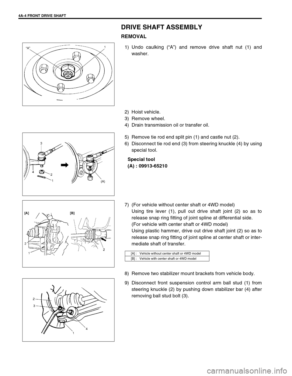
1) Undo caulking (“A”) and remove drive shaft nut (1) and
washer.
2) Hoist vehicle.
3) Remove wheel.
4) Drain transmission oil or transfer oil.
5) Remove tie rod end split pin (1) and castle nut (2).
6) Disconnect tie rod end (3) from steering knuckle (4) by using
special tool.
Special tool
(A) : 09913-65210
7) (For vehicle without center shaft or 4WD model)
Using tire lever (1), pull out drive shaft joint (2) so as to
release snap ring fitting of joint spline at differential side.
(For vehicle with center shaft or 4WD model)
Using plastic hammer, drive out drive shaft joint (2) so as to
release snap ring fitting of joint spline at center shaft or inter-
mediate shaft of transfer.
8) Remove two stabilizer mount brackets from vehicle body.
9) Disconnect front suspension control arm ball stud (1) from
steering knuckle (2) by pushing down stabilizer bar (4) after
removing ball stud bolt (3).
[A] : Vehicle without center shaft or 4WD model
[B] : Vehicle with center shaft or 4WD model
Page 268 of 698
FRONT DRIVE SHAFT 4A-15
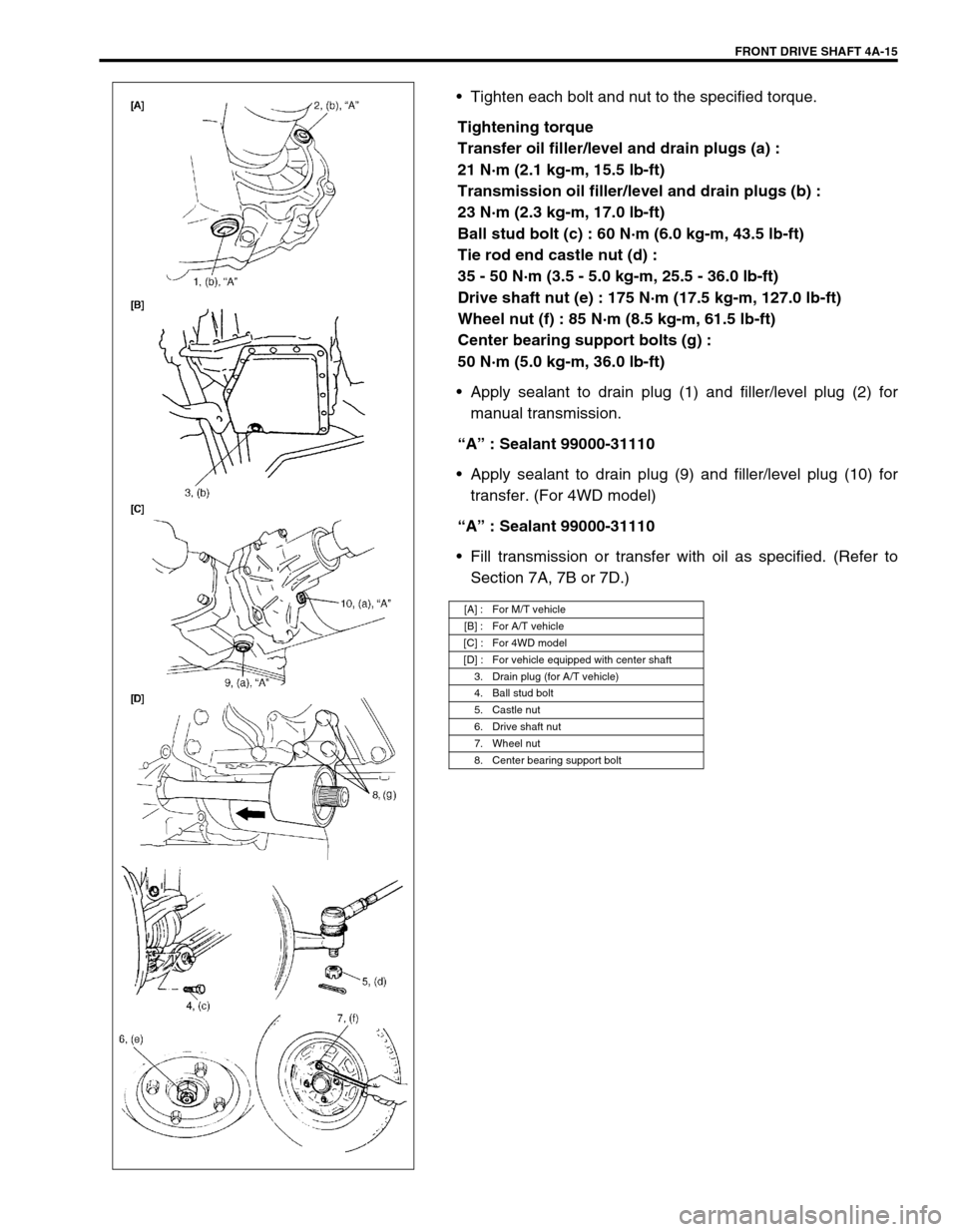
Tighten each bolt and nut to the specified torque.
Tightening torque
Transfer oil filler/level and drain plugs (a) :
21 N·m (2.1 kg-m, 15.5 lb-ft)
Transmission oil filler/level and drain plugs (b) :
23 N·m (2.3 kg-m, 17.0 lb-ft)
Ball stud bolt (c) : 60 N·m (6.0 kg-m, 43.5 lb-ft)
Tie rod end castle nut (d) :
35 - 50 N·m (3.5 - 5.0 kg-m, 25.5 - 36.0 lb-ft)
Drive shaft nut (e) : 175 N·m (17.5 kg-m, 127.0 lb-ft)
Wheel nut (f) : 85 N·m (8.5 kg-m, 61.5 lb-ft)
Center bearing support bolts (g) :
50 N·m (5.0 kg-m, 36.0 lb-ft)
Apply sealant to drain plug (1) and filler/level plug (2) for
manual transmission.
“A” : Sealant 99000-31110
Apply sealant to drain plug (9) and filler/level plug (10) for
transfer. (For 4WD model)
“A” : Sealant 99000-31110
Fill transmission or transfer with oil as specified. (Refer to
Section 7A, 7B or 7D.)
[A] : For M/T vehicle
[B] : For A/T vehicle
[C] : For 4WD model
[D] : For vehicle equipped with center shaft
3. Drain plug (for A/T vehicle)
4. Ball stud bolt
5. Castle nut
6. Drive shaft nut
7. Wheel nut
8. Center bearing support bolt
Page 269 of 698
4A-16 FRONT DRIVE SHAFT
TIGHTENING TORQUE SPECIFICATION
REQUIRED SERVICE MATERIAL
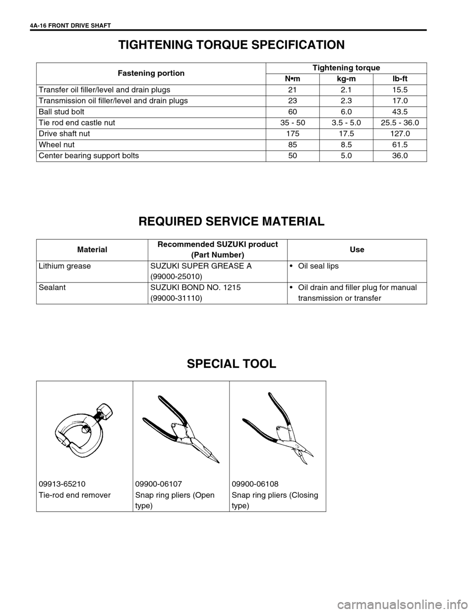
SPECIAL TOOL
Fastening portionTightening torque
Nm kg-m lb-ft
Transfer oil filler/level and drain plugs 21 2.1 15.5
Transmission oil filler/level and drain plugs 23 2.3 17.0
Ball stud bolt 60 6.0 43.5
Tie rod end castle nut 35 - 50 3.5 - 5.0 25.5 - 36.0
Drive shaft nut 175 17.5 127.0
Wheel nut 85 8.5 61.5
Center bearing support bolts 50 5.0 36.0
MaterialRecommended SUZUKI product
(Part Number)Use
Lithium grease SUZUKI SUPER GREASE A
(99000-25010)Oil seal lips
Sealant SUZUKI BOND NO. 1215
(99000-31110)Oil drain and filler plug for manual
transmission or transfer
09913-65210 09900-06107 09900-06108
Tie-rod end remover Snap ring pliers (Open
type)Snap ring pliers (Closing
type)
Page 290 of 698
BRAKES 5-17
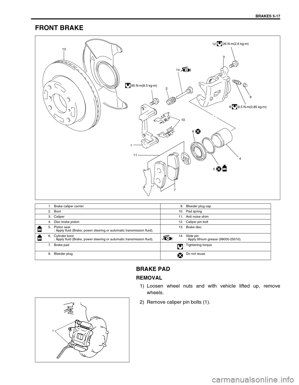
FRONT BRAKE
BRAKE PAD
REMOVAL
1) Loosen wheel nuts and with vehicle lifted up, remove
wheels.
2) Remove caliper pin bolts (1).
1. Brake caliper carrier 9. Bleeder plug cap
2. Boot 10. Pad spring
3. Caliper 11. Anti noise shim
4. Disc brake piston 12. Caliper pin bolt
5. Piston seal
: Apply fluid (Brake, power steering or automatic transmission fluid).13. Brake disc
6. Cylinder boot
: Apply fluid (Brake, power steering or automatic transmission fluid).14. Slide pin
: Apply lithium grease (99000-25010).
7. Brake pad Tightening torque
8. Bleeder plugDo not reuse.
9
1
7
13
2
143
1226 N·m(2.6 kg-m)
85 N·m(8.5 kg-m)
8
8.5 N·m(0.85 kg-m)
10
5 4
6
11
Page 356 of 698
ANTILOCK BRAKE SYSTEM (ABS) 5E-31
ON-VEHICLE SERVICE
PRECAUTIONS
When connector is connected to ABS hydraulic unit/control mod-
ule assembly, do not disconnect connectors of sensors with igni-
tion switch ON. Then DTC will be set in ABS control module.
ABS HYDRAULIC UNIT OPERATION CHECK
(USING SUZUKI SCAN TOOL)
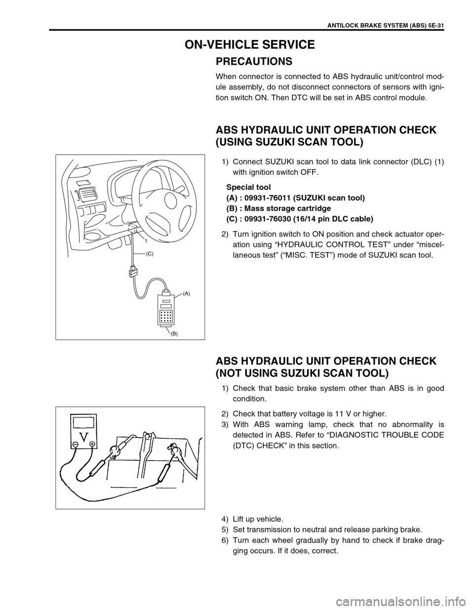
1) Connect SUZUKI scan tool to data link connector (DLC) (1)
with ignition switch OFF.
Special tool
(A) : 09931-76011 (SUZUKI scan tool)
(B) : Mass storage cartridge
(C) : 09931-76030 (16/14 pin DLC cable)
2) Turn ignition switch to ON position and check actuator oper-
ation using “HYDRAULIC CONTROL TEST” under “miscel-
laneous test” (“MISC. TEST”) mode of SUZUKI scan tool.
ABS HYDRAULIC UNIT OPERATION CHECK
(NOT USING SUZUKI SCAN TOOL)
1) Check that basic brake system other than ABS is in good
condition.
2) Check that battery voltage is 11 V or higher.
3) With ABS warning lamp, check that no abnormality is
detected in ABS. Refer to “DIAGNOSTIC TROUBLE CODE
(DTC) CHECK” in this section.
4) Lift up vehicle.
5) Set transmission to neutral and release parking brake.
6) Turn each wheel gradually by hand to check if brake drag-
ging occurs. If it does, correct.
(A)
(B) (C) 1
Page 375 of 698
6-6 ENGINE GENERAL INFORMATION AND DIAGNOSIS
FUEL PRESSURE RELIEF PROCEDURE
After making sure that engine is cold, release fuel pressure as fol-
lows.
1) Place transmission gear shift lever in “Neutral” (Shift selector
lever to “P” range for A/T model), set parking brake, and
block drive wheels.
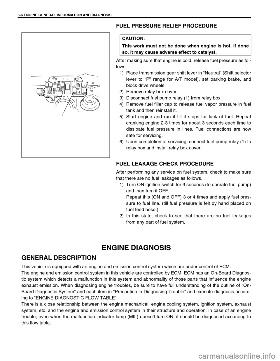
2) Remove relay box cover.
3) Disconnect fuel pump relay (1) from relay box.
4) Remove fuel filler cap to release fuel vapor pressure in fuel
tank and then reinstall it.
5) Start engine and run it till it stops for lack of fuel. Repeat
cranking engine 2-3 times for about 3 seconds each time to
dissipate fuel pressure in lines. Fuel connections are now
safe for servicing.
6) Upon completion of servicing, connect fuel pump relay (1) to
relay box and install relay box cover.
FUEL LEAKAGE CHECK PROCEDURE
After performing any service on fuel system, check to make sure
that there are no fuel leakages as follows.
1) Turn ON ignition switch for 3 seconds (to operate fuel pump)
and then turn it OFF.
Repeat this (ON and OFF) 3 or 4 times and apply fuel pres-
sure to fuel line. (till fuel pressure is felt by hand placed on
fuel feed hose.)
2) In this state, check to see that there are no fuel leakages
from any part of fuel system.
ENGINE DIAGNOSIS
GENERAL DESCRIPTION
This vehicle is equipped with an engine and emission control system which are under control of ECM.
The engine and emission control system in this vehicle are controlled by ECM. ECM has an On-Board Diagnos-
tic system which detects a malfunction in this system and abnormality of those parts that influence the engine
exhaust emission. When diagnosing engine troubles, be sure to have full understanding of the outline of “On-
Board Diagnostic System” and each item in “Precaution in Diagnosing Trouble” and execute diagnosis accord-
ing to “ENGINE DIAGNOSTIC FLOW TABLE”.
There is a close relationship between the engine mechanical, engine cooling system, ignition system, exhaust
system, etc. and the engine and emission control system in their structure and operation. In case of an engine
trouble, even when the malfunction indicator lamp (MIL) doesn’t turn ON, it should be diagnosed according to
this flow table.CAUTION:
This work must not be done when engine is hot. If done
so, it may cause adverse effect to catalyst.
1