wiring SUZUKI SWIFT 2000 1.G RG413 Service Workshop Manual
[x] Cancel search | Manufacturer: SUZUKI, Model Year: 2000, Model line: SWIFT, Model: SUZUKI SWIFT 2000 1.GPages: 698, PDF Size: 16.01 MB
Page 1 of 698
IMPORTANT
WARNING/CAUTION/NOTE
Please read this manual and follow its instructions carefully. To emphasize special information, the words
WARNING, CAUTION
and NOTE
have special meanings. Pay special attention to the messages highlighted by
these signal words.
WARNING:
Indicates a potential hazard that could result in death or injury.
CAUTION:
Indicates a potential hazard that could result in vehicle damage.
NOTE:
Indicates special information to make maintenance easier or instructions clearer.
WARNING:
This service manual is intended for authorized Suzuki dealers and qualified service mechanics only.
Inexperienced mechanics or mechanics without the proper tools and equipment may not be able to
properly perform the services described in this manual.
Improper repair may result in injury to the mechanic and may render the vehicle unsafe for the driver
and passengers.
WARNING:
For vehicles equipped with a Supplemental Restraint (Air Bag) System:
• Service on and around the air bag system components or wiring must be performed only by an
authorized SUZUKI dealer. Refer to “Air Bag System Components and Wiring Location View” under
“General Description” in air bag system section in order to confirm whether you are performing ser-
vice on or near the air bag system components or wiring. Please observe all WARNINGS and “Ser-
vice Precautions” under “On-Vehicle Service” in air bag system section before performing service
on or around the air bag system components or wiring. Failure to follow WARNINGS could result in
unintentional activation of the system or could render the system inoperative. Either of these two
conditions may result in severe injury.
If the air bag system and another vehicle system both need repair, Suzuki recommends that the air
bag system be repaired first, to help avoid unintended air bag system activation.
Do not modify the steering wheel, instrument panel or any other air bag system component (on or
around air bag system components or wiring). Modifications can adversely affect air bag system
performance and lead to injury.
If the vehicle will be exposed to temperatures over 93°C (200°F) (for example, during a paint baking
process), remove the air bag system components (air bag (inflator) modules, SDM and/or seat belt
with pretensioner) beforehand to avoid component damage or unintended activation.
Page 2 of 698
FOREWORD
This manual contains procedures for diagnosis, maintenance, adjustments, minor service operations, replace-
ment of components (Service) and for disassembly and assembly of major components (Unit Repair-Overhaul).
Applicable model: RG413
The contents are classified into sections each of which is given a section number as indicated in the Table of
Contents on following page. And on the first page of each individual section is an index of that section.
This manual should be kept in a handy place for ready reference of the service work.
Strict observance of the so specified items will enable one to obtain the full performance of the vehicle.
When replacing parts or servicing by disassembling, it is recommended to use SUZUKI genuine parts, tools and
service materials (lubricant, sealants, etc.) as specified in each description.
All information, illustrations and specifications contained in this literature are based on the latest product infor-
mation available at the time of publication approval. And used as the main subject of description is the vehicle of
standard specifications among others.
Therefore, note that illustrations may differ from the vehicle being actually serviced.
The right is reserved to make changes at any time without notice.
Related Manual
© COPYRIGHT SUZUKI MOTOR CORPORATION 2000Manual Name Manual No.
RG413 Wiring Diagram Manual 99512-80G00-015
Page 3 of 698
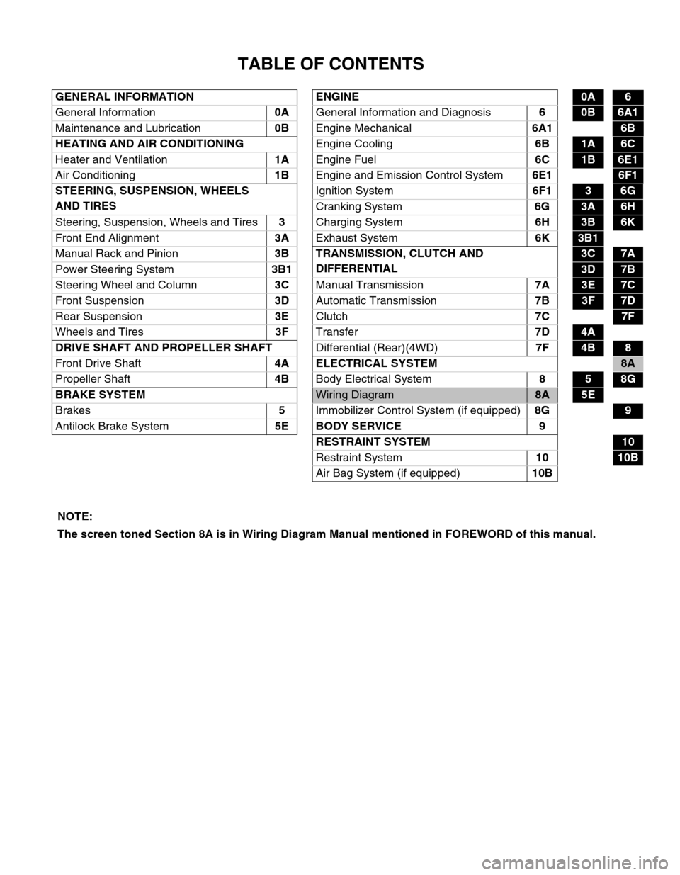
TABLE OF CONTENTS
GENERAL INFORMATION ENGINE0A6
General Information0A
General Information and Diagnosis6
0B6A1
Maintenance and Lubrication0B
Engine Mechanical6A1
6B
HEATING AND AIR CONDITIONING
Engine Cooling6B
1A6C
Heater and Ventilation1A
Engine Fuel6C
1B6E1
Air Conditioning1B
Engine and Emission Control System6E1
6F1
STEERING, SUSPENSION, WHEELS
AND TIRESIgnition System6F1
36G
Cranking System6G
3A6H
Steering, Suspension, Wheels and Tires3
Charging System6H
3B6K
Front End Alignment3A
Exhaust System6K
3B1 6B
Manual Rack and Pinion3B TRANSMISSION, CLUTCH AND
DIFFERENTIAL
3C7A
Power Steering System3B1
3D7B
Steering Wheel and Column3C
Manual Transmission7A
3E7C
Front Suspension3D
Automatic Transmission7B
3F7D
Rear Suspension3E
Clutch7C
7F
Wheels and Tires3F
Transfer7D
4A
DRIVE SHAFT AND PROPELLER SHAFT
Differential (Rear)(4WD)7F
4B8
Front Drive Shaft 4A ELECTRICAL SYSTEM
8A
Propeller Shaft4B
Body Electrical System8
58G
BRAKE SYSTEM
Wiring Diagram8A5E
Brakes5
Immobilizer Control System (if equipped)8G
9
Antilock Brake System5E BODY SERVICE 9
RESTRAINT SYSTEM
10
Restraint System10
10B
Air Bag System (if equipped)10B
NOTE:
The screen toned Section 8A is in Wiring Diagram Manual mentioned in FOREWORD of this manual.
Page 14 of 698
GENERAL INFORMATION 0A-11
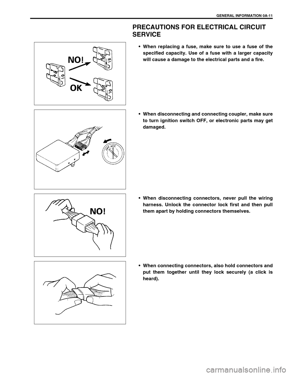
PRECAUTIONS FOR ELECTRICAL CIRCUIT
SERVICE
When replacing a fuse, make sure to use a fuse of the
specified capacity. Use of a fuse with a larger capacity
will cause a damage to the electrical parts and a fire.
When disconnecting and connecting coupler, make sure
to turn ignition switch OFF, or electronic parts may get
damaged.
When disconnecting connectors, never pull the wiring
harness. Unlock the connector lock first and then pull
them apart by holding connectors themselves.
When connecting connectors, also hold connectors and
put them together until they lock securely (a click is
heard).
Page 15 of 698
0A-12 GENERAL INFORMATION
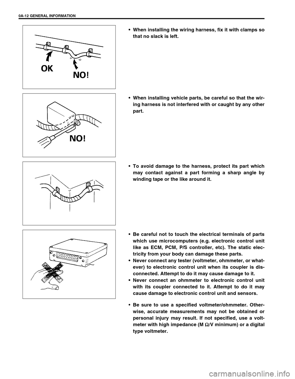
When installing the wiring harness, fix it with clamps so
that no slack is left.
When installing vehicle parts, be careful so that the wir-
ing harness is not interfered with or caught by any other
part.
To avoid damage to the harness, protect its part which
may contact against a part forming a sharp angle by
winding tape or the like around it.
Be careful not to touch the electrical terminals of parts
which use microcomputers (e.g. electronic control unit
like as ECM, PCM, P/S controller, etc). The static elec-
tricity from your body can damage these parts.
Never connect any tester (voltmeter, ohmmeter, or what-
ever) to electronic control unit when its coupler is dis-
connected. Attempt to do it may cause damage to it.
Never connect an ohmmeter to electronic control unit
with its coupler connected to it. Attempt to do it may
cause damage to electronic control unit and sensors.
Be sure to use a specified voltmeter/ohmmeter. Other-
wise, accurate measurements may not be obtained or
personal injury may result. If not specified, use a volt-
meter with high impedance (M
Ω/
Ω/Ω/ Ω/V minimum) or a digital
type voltmeter.
Page 19 of 698
0A-16 GENERAL INFORMATION
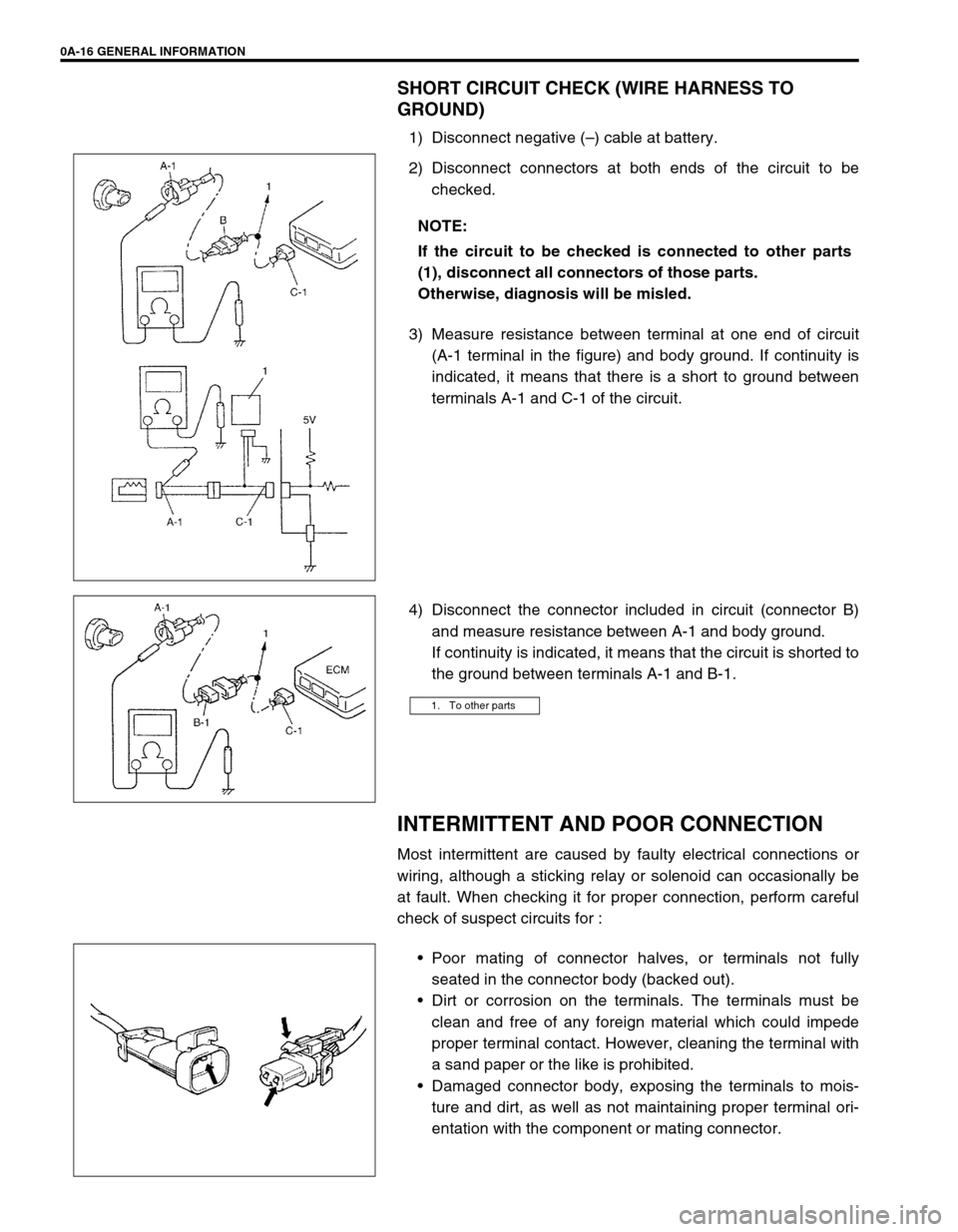
SHORT CIRCUIT CHECK (WIRE HARNESS TO
GROUND)
1) Disconnect negative (–) cable at battery.
2) Disconnect connectors at both ends of the circuit to be
checked.
3) Measure resistance between terminal at one end of circuit
(A-1 terminal in the figure) and body ground. If continuity is
indicated, it means that there is a short to ground between
terminals A-1 and C-1 of the circuit.
4) Disconnect the connector included in circuit (connector B)
and measure resistance between A-1 and body ground.
If continuity is indicated, it means that the circuit is shorted to
the ground between terminals A-1 and B-1.
INTERMITTENT AND POOR CONNECTION
Most intermittent are caused by faulty electrical connections or
wiring, although a sticking relay or solenoid can occasionally be
at fault. When checking it for proper connection, perform careful
check of suspect circuits for :
Poor mating of connector halves, or terminals not fully
seated in the connector body (backed out).
Dirt or corrosion on the terminals. The terminals must be
clean and free of any foreign material which could impede
proper terminal contact. However, cleaning the terminal with
a sand paper or the like is prohibited.
Damaged connector body, exposing the terminals to mois-
ture and dirt, as well as not maintaining proper terminal ori-
entation with the component or mating connector. NOTE:
If the circuit to be checked is connected to other parts
(1), disconnect all connectors of those parts.
Otherwise, diagnosis will be misled.
1. To other parts
Page 20 of 698
GENERAL INFORMATION 0A-17
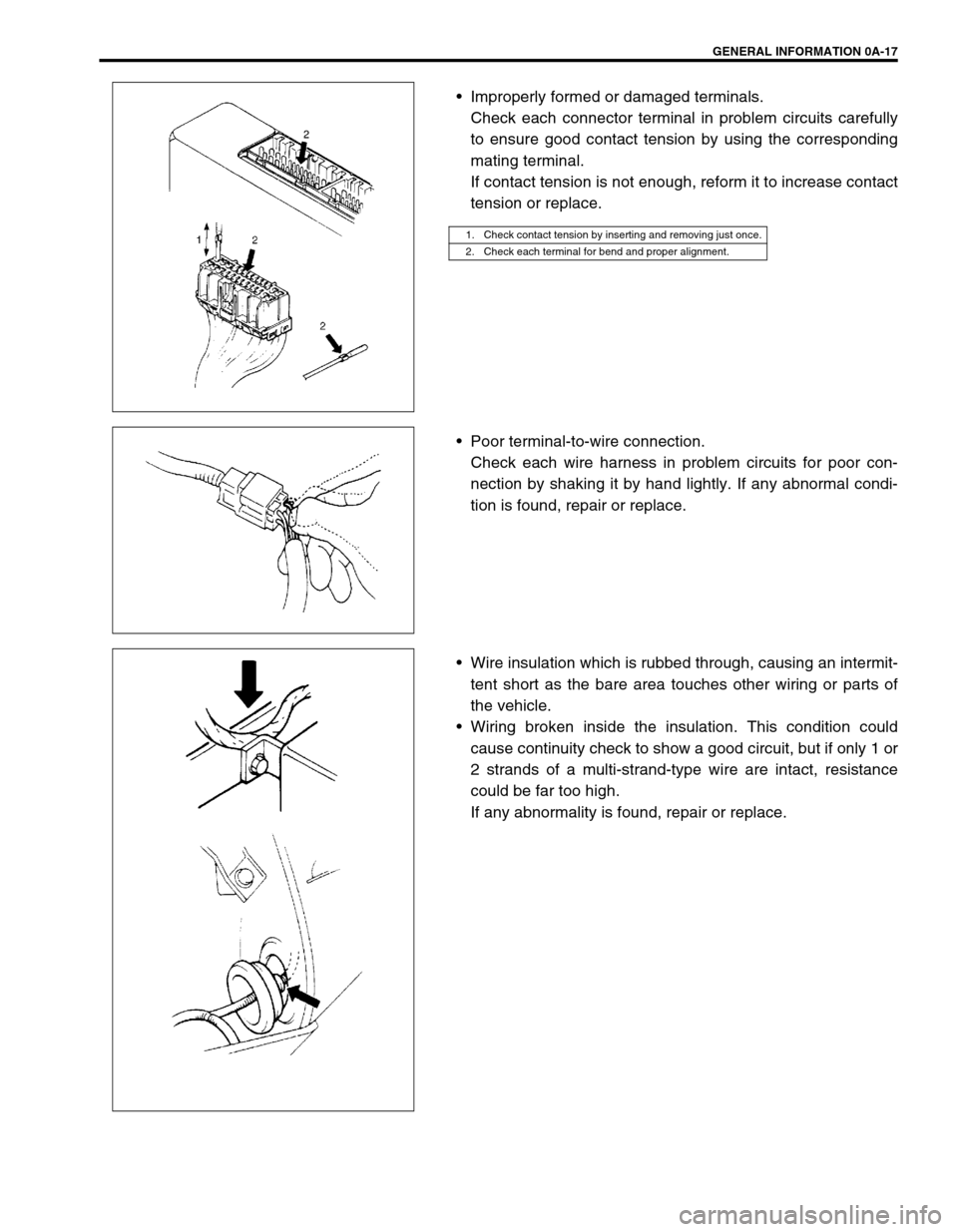
Improperly formed or damaged terminals.
Check each connector terminal in problem circuits carefully
to ensure good contact tension by using the corresponding
mating terminal.
If contact tension is not enough, reform it to increase contact
tension or replace.
Poor terminal-to-wire connection.
Check each wire harness in problem circuits for poor con-
nection by shaking it by hand lightly. If any abnormal condi-
tion is found, repair or replace.
Wire insulation which is rubbed through, causing an intermit-
tent short as the bare area touches other wiring or parts of
the vehicle.
Wiring broken inside the insulation. This condition could
cause continuity check to show a good circuit, but if only 1 or
2 strands of a multi-strand-type wire are intact, resistance
could be far too high.
If any abnormality is found, repair or replace.
1. Check contact tension by inserting and removing just once.
2. Check each terminal for bend and proper alignment.
Page 30 of 698
MAINTENANCE AND LUBRICATION 0B-1
0A 6F1
0B
0B
6G
1A 6H
1B 6K
37A
3A 7A1
3B1 7B1
3C1 7C1
3D 7D
3E 7E
3F 7F
4A2 8A
4B 8B
8C
58D
5A 8E
5B
5C 9
5E
5E1 10
10A
610B
6-1
6A1
6A2
6A4
6B
6C
6E1
6E2
SECTION 0B
MAINTENANCE AND LUBRICATION
CONTENTS
MAINTENANCE SCHEDULE .......................... 0B-2
MAINTENANCE SCHEDULE UNDER
NORMAL DRIVING CONDITIONS .............. 0B-2
MAINTENANCE RECOMMENDED UNDER
SEVERE DRIVING CONDITIONS ............... 0B-4
MAINTENANCE SERVICE .............................. 0B-5
ENGINE ....................................................... 0B-5
DRIVE BELT ............................................ 0B-5
VALVE LASH (CLEARANCE) .................. 0B-6
ENGINE OIL AND OIL FILTER ................ 0B-6
ENGINE COOLANT ................................. 0B-8
EXHAUST SYSTEM............................... 0B-10
IGNITION SYSTEM ................................... 0B-10
SPARK PLUGS ...................................... 0B-10
FUEL SYSTEM .......................................... 0B-10
AIR CLEANER FILTER .......................... 0B-10
FUEL LINES AND CONNECTIONS....... 0B-11
FUEL FILTER ......................................... 0B-11
FUEL TANK............................................ 0B-12
EMISSION CONTROL SYSTEM ............... 0B-12
PCV VALVE ........................................... 0B-12
FUEL EVAPORATIVE EMISSION
CONTROL SYSTEM .............................. 0B-12BRAKE ....................................................... 0B-12
BRAKE DISCS AND PADS (FRONT) .... 0B-12
BRAKE DRUMS AND SHOES
(REAR) ................................................... 0B-13
BRAKE HOSES AND PIPES ................. 0B-13
BRAKE FLUID........................................ 0B-13
BRAKE LEVER AND CABLE ................. 0B-13
CHASSIS AND BODY ............................... 0B-14
CLUTCH................................................. 0B-14
TIRES / WHEELS .................................. 0B-14
SUSPENSION SYSTEM ........................ 0B-15
STEERING SYSTEM ............................. 0B-15
DRIVE SHAFT (AXLE) BOOTS /
PROPELLER SHAFTS (4WD) ............... 0B-16
MANUAL TRANSMISSION OIL ............. 0B-17
AUTOMATIC TRANSMISSION FLUID .. 0B-17
TRANSFER OIL (4WD) AND REAR
DIFFERENTIAL OIL (4WD) ................... 0B-18
ALL LATCHES, HINGES AND
LOCKS ................................................... 0B-19
FINAL INSPECTION ..................................... 0B-19
RECOMMENDED FLUIDS AND
LUBRICANTS................................................ 0B-21
WARNING:
For vehicles equipped with Supplemental Restraint (Air Bag) System:
Service on and around the air bag system components or wiring must be performed only by an
authorized SUZUKI dealer. Refer to “Air Bag System Components and Wiring Location View” under
“General Description” in air bag system section in order to confirm whether you are performing ser-
vice on or near the air bag system components or wiring. Please observe all WARNINGS and “Ser-
vice Precautions” under “On-Vehicle Service” in air bag system section before performing service
on or around the air bag system components or wiring. Failure to follow WARNINGS could result in
unintentional activation of the system or could render the system inoperative. Either of these two
conditions may result in severe injury.
Technical service work must be started at least 90 seconds after the ignition switch is turned to the
“LOCK” position and the negative cable is disconnected from the battery. Otherwise, the system
may be activated by reserve energy in the Sensing and Diagnostic Module (SDM).
Page 52 of 698
HEATER AND VENTILATION 1A-1
6F1
6F2
6G
1A
6K
7A
7A1
7B1
7C1
7D
7E
7F
8A
8B
8C
8D
8E
9
10
10A
10B
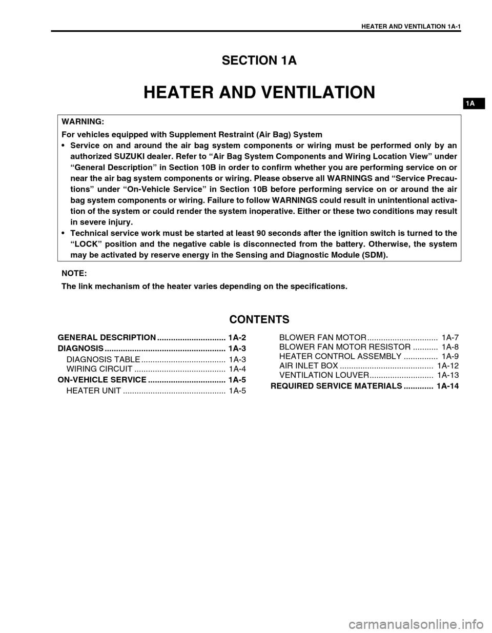
SECTION 1A
HEATER AND VENTILATION
CONTENTS
GENERAL DESCRIPTION .............................. 1A-2
DIAGNOSIS ..................................................... 1A-3
DIAGNOSIS TABLE ..................................... 1A-3
WIRING CIRCUIT ........................................ 1A-4
ON-VEHICLE SERVICE .................................. 1A-5
HEATER UNIT ............................................. 1A-5BLOWER FAN MOTOR ............................... 1A-7
BLOWER FAN MOTOR RESISTOR ........... 1A-8
HEATER CONTROL ASSEMBLY ............... 1A-9
AIR INLET BOX ......................................... 1A-12
VENTILATION LOUVER............................ 1A-13
REQUIRED SERVICE MATERIALS ............. 1A-14
WARNING:
For vehicles equipped with Supplement Restraint (Air Bag) System
Service on and around the air bag system components or wiring must be performed only by an
authorized SUZUKI dealer. Refer to “Air Bag System Components and Wiring Location View” under
“General Description” in Section 10B in order to confirm whether you are performing service on or
near the air bag system components or wiring. Please observe all WARNINGS and “Service Precau-
tions” under “On-Vehicle Service” in Section 10B before performing service on or around the air
bag system components or wiring. Failure to follow WARNINGS could result in unintentional activa-
tion of the system or could render the system inoperative. Either or these two conditions may result
in severe injury.
Technical service work must be started at least 90 seconds after the ignition switch is turned to the
“LOCK” position and the negative cable is disconnected from the battery. Otherwise, the system
may be activated by reserve energy in the Sensing and Diagnostic Module (SDM).
NOTE:
The link mechanism of the heater varies depending on the specifications.
Page 54 of 698
HEATER AND VENTILATION 1A-3
DIAGNOSIS
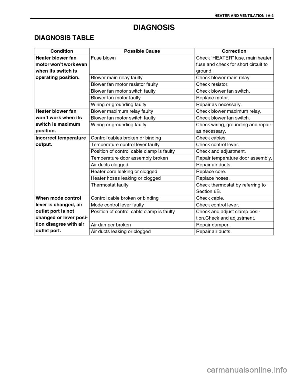
DIAGNOSIS TABLE
Condition Possible Cause Correction
Heater blower fan
motor won’t work even
when its switch is
operating position.Fuse blown Check “HEATER” fuse, main heater
fuse and check for short circuit to
ground.
Blower main relay faulty Check blower main relay.
Blower fan motor resistor faulty Check resistor.
Blower fan motor switch faulty Check blower fan switch.
Blower fan motor faulty Replace motor.
Wiring or grounding faulty Repair as necessary.
Heater blower fan
won’t work when its
switch is maximum
position.Blower maximum relay faulty Check blower maximum relay.
Blower fan motor switch faulty Check blower fan switch.
Wiring or grounding faulty Check wiring, grounding and repair
as necessary.
Incorrect temperature
output.Control cables broken or binding Check cables.
Temperature control lever faulty Check control lever.
Position of control cable clamp is faulty Check and adjustment.
Temperature door assembly broken Repair temperature door assembly.
Air ducts clogged Repair air ducts.
Heater core leaking or clogged Replace core.
Heater hoses leaking or clogged Replace hoses.
Thermostat faulty Check thermostat by referring to
Section 6B.
When mode control
lever is changed, air
outlet port is not
changed or lever posi-
tion disagree with air
outlet port.Control cable broken or binding Check cable.
Mode control lever faulty Check control lever.
Position of control cable clamp is faulty Check and adjust clamp posi-
tion.Check and adjustment.
Air damper broken Repair damper.
Air ducts leaking or clogged Repair air ducts.