oil SUZUKI SWIFT 2000 1.G RG413 Service Workshop Manual
[x] Cancel search | Manufacturer: SUZUKI, Model Year: 2000, Model line: SWIFT, Model: SUZUKI SWIFT 2000 1.GPages: 698, PDF Size: 16.01 MB
Page 678 of 698
6G-6 CRANKING SYSTEM
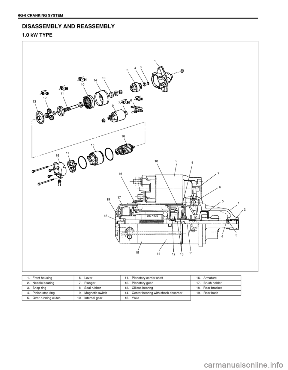
DISASSEMBLY AND REASSEMBLY
1.0 kW TYPE
1. Front housing 6. Lever 11. Planetary carrier shaft 16. Armature
2. Needle bearing 7. Plunger 12. Planetary gear 17. Brush holder
3. Snap ring 8. Seal rubber 13. Oilless bearing 18. Rear bracket
4. Pinion stop ring 9. Magnetic switch 14. Center bearing with shock absorber 19. Rear bush
5. Over-running clutch 10. Internal gear 15. Yoke
Page 684 of 698
6H-4 CHARGING SYSTEM
GENERATOR
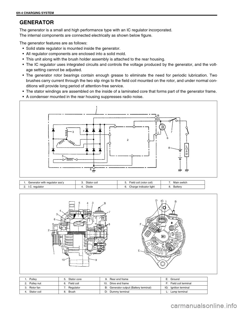
The generator is a small and high performance type with an IC regulator incorporated.
The internal components are connected electrically as shown below figure.
The generator features are as follows:
Solid state regulator is mounted inside the generator.
All regulator components are enclosed into a solid mold.
This unit along with the brush holder assembly is attached to the rear housing.
The IC regulator uses integrated circuits and controls the voltage produced by the generator, and the volt-
age setting cannot be adjusted.
The generator rotor bearings contain enough grease to eliminate the need for periodic lubrication. Two
brushes carry current through the two slip rings to the field coil mounted on the rotor, and under normal con-
ditions will provide long period of attention-free service.
The stator windings are assembled on the inside of a laminated core that forms part of the generator frame.
A condenser mounted in the rear housing suppresses radio noise.
1. Generator with regulator ass’y 3. Stator coil 5. Field coil (rotor coil) 7. Main switch
2. I.C. regulator 4. Diode 6. Charge indicator light 8. Battery
1. Pulley 5. Stator core 9. Rear end frame E: Ground
2. Pulley nut 6. Field coil 10. Drive end frame F: Field coil terminal
3. Rotor fan 7. Regulator B: Generator output (Battery terminal) IG: Ignition terminal
4. Stator coil 8. Brush D: Dummy terminal L: Lamp terminal
Page 686 of 698
6H-6 CHARGING SYSTEM
GENERATOR
Trouble in charging system will show up as one or more of the fol-
lowing conditions:
1) Faulty indicator lamp operation.
2) An undercharged battery as evidenced by slow cranking or
indicator dark.
3) An overcharged battery as evidenced by excessive spewing
of electrolyte from vents.
Noise from generator may be caused by loose drive pulley, loose
mounting bolts, worn or dirty bearings, defective diode, or defec-
tive stator.
CHARGING INDICATOR LAMP OPERATION
CAUTION:
Do not mistake polarities of IG terminal and L terminal.
Do not create short circuit between IG and L terminals.
Always connect these terminals through a lamp.
Do not connect any load between L and E.
When connecting charger or booster battery to vehicle
battery, refer to this section describing battery charg-
ing.
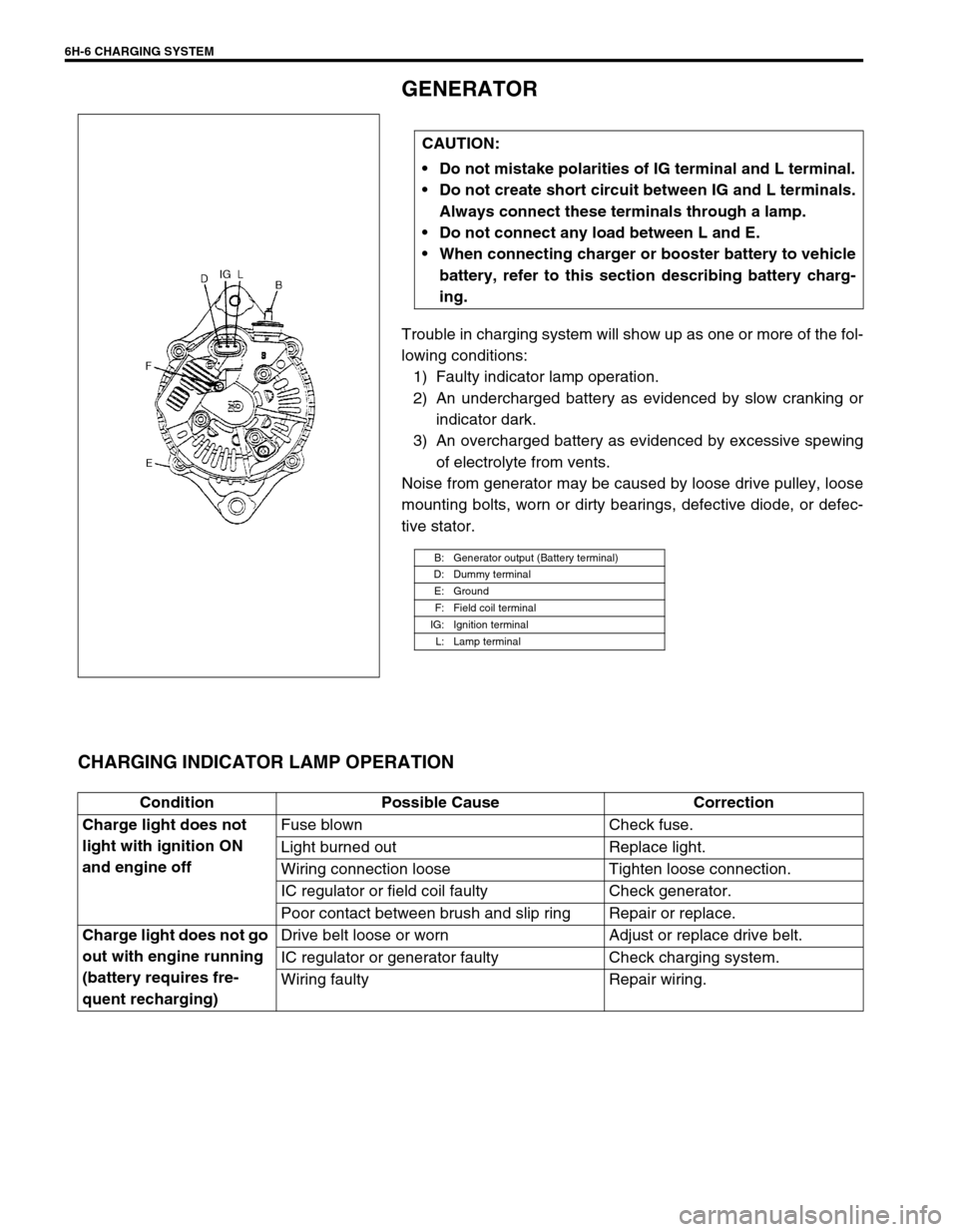
B: Generator output (Battery terminal)
D: Dummy terminal
E: Ground
F: Field coil terminal
IG: Ignition terminal
L: Lamp terminal
Condition Possible Cause Correction
Charge light does not
light with ignition ON
and engine offFuse blown Check fuse.
Light burned out Replace light.
Wiring connection loose Tighten loose connection.
IC regulator or field coil faulty Check generator.
Poor contact between brush and slip ring Repair or replace.
Charge light does not go
out with engine running
(battery requires fre-
quent recharging)Drive belt loose or worn Adjust or replace drive belt.
IC regulator or generator faulty Check charging system.
Wiring faulty Repair wiring.
Page 688 of 698
6H-8 CHARGING SYSTEM
3) Ground F terminal and start engine, then measure voltage at
B terminal as shown in left figure.
Voltage is higher than standard value
It is considered that generator itself is good but IC regulator
has been damaged, replace IC regulator.
Voltage is lower than standard value
Generator itself has problem, check the generator.
LOAD CHECK
1) Run engine at 2,000 rpm and turn on head light and heater
motor.
2) Measure current and if it is less than 20 A repair or replace
generator.
OVERCHARGED BATTERY
1) To determine battery condition, refer to Battery section.
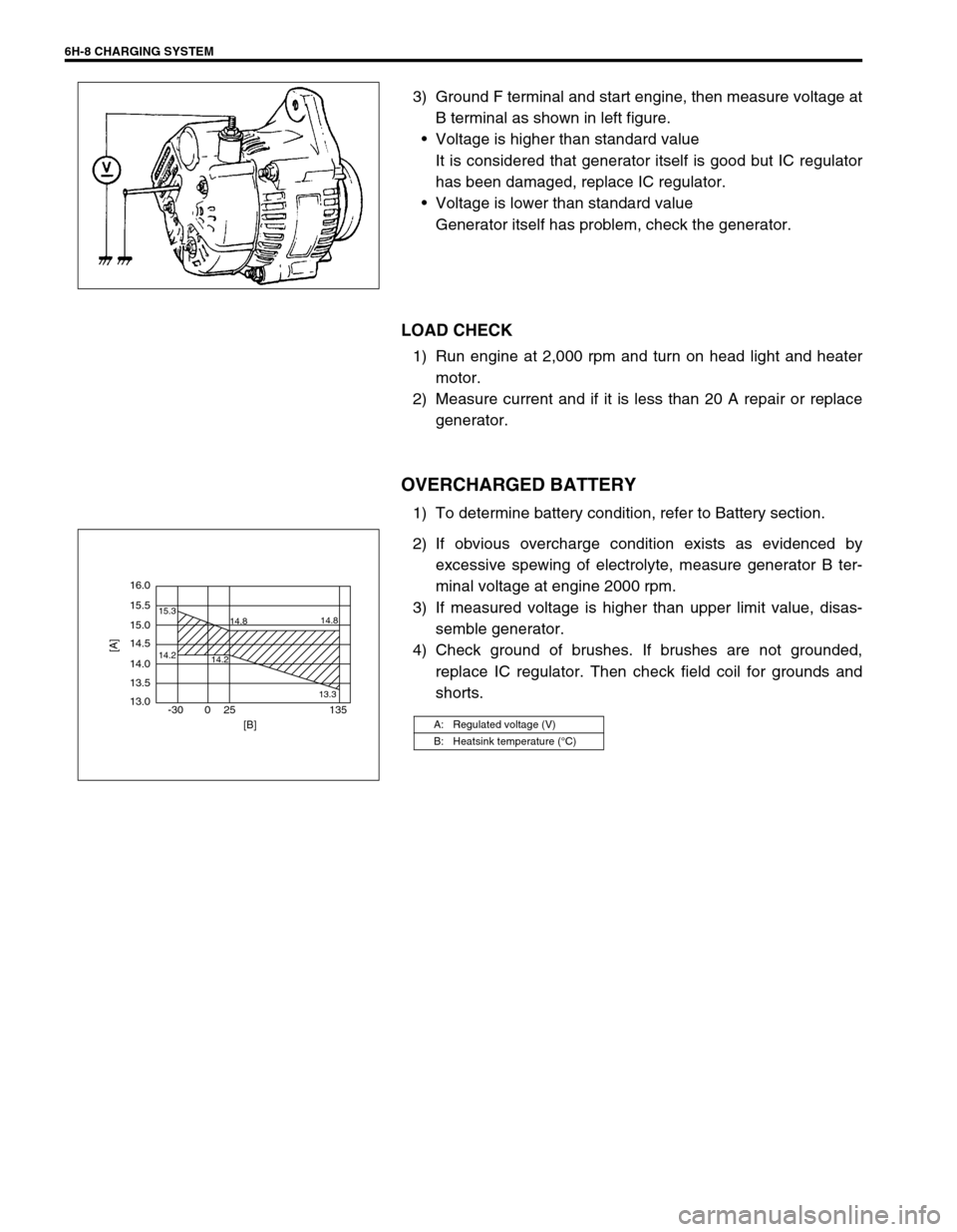
2) If obvious overcharge condition exists as evidenced by
excessive spewing of electrolyte, measure generator B ter-
minal voltage at engine 2000 rpm.
3) If measured voltage is higher than upper limit value, disas-
semble generator.
4) Check ground of brushes. If brushes are not grounded,
replace IC regulator. Then check field coil for grounds and
shorts.
A: Regulated voltage (V)
B: Heatsink temperature (°C)
16.0
15.5
14.2 15.3
14.8
14.2
13.314.8
15.0
14.5
14.0
13.5
13.0
-30 0 25 135
[A]
[B]
Page 693 of 698
CHARGING SYSTEM 6H-13
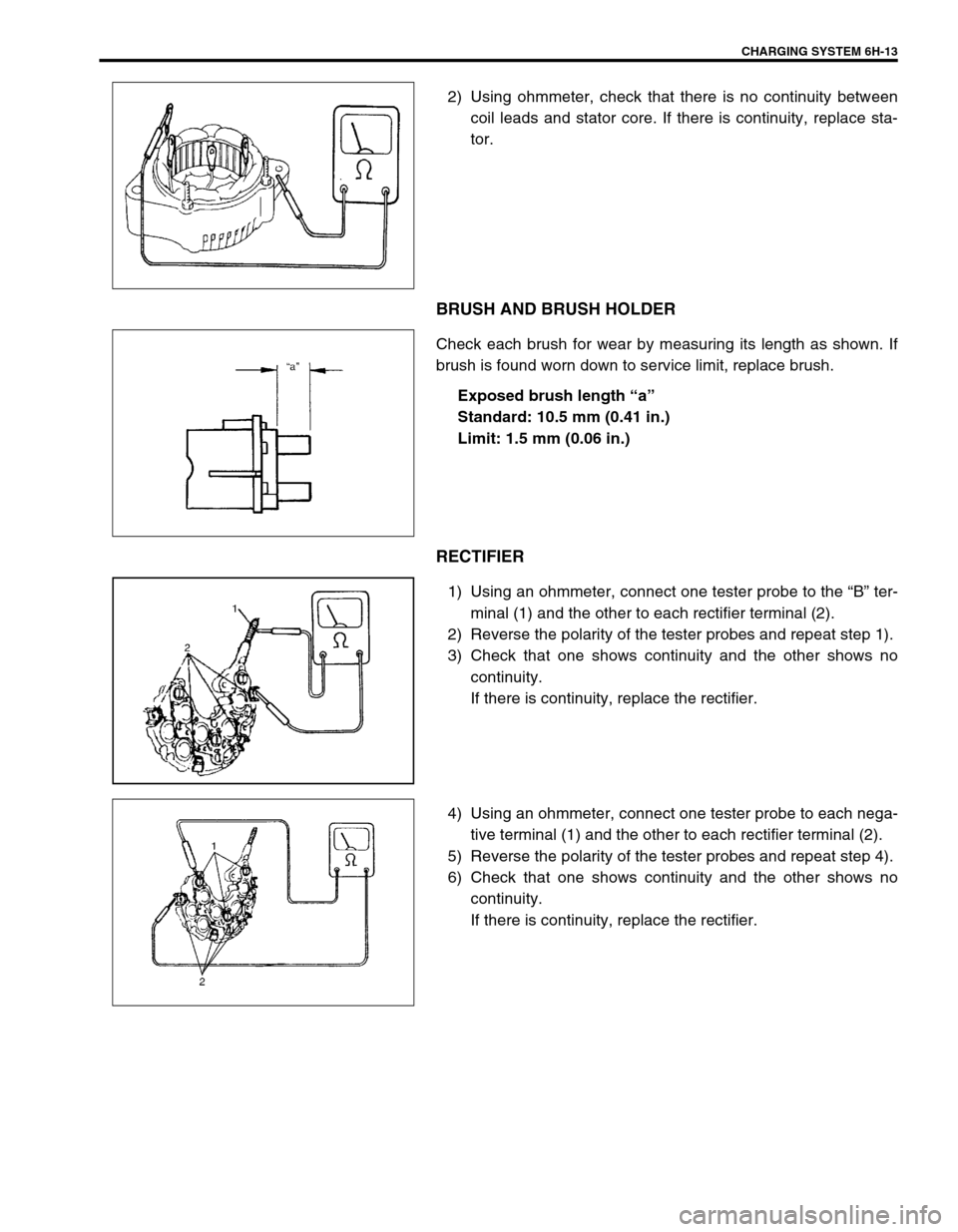
2) Using ohmmeter, check that there is no continuity between
coil leads and stator core. If there is continuity, replace sta-
tor.
BRUSH AND BRUSH HOLDER
Check each brush for wear by measuring its length as shown. If
brush is found worn down to service limit, replace brush.
Exposed brush length “a”
Standard: 10.5 mm (0.41 in.)
Limit: 1.5 mm (0.06 in.)
RECTIFIER
1) Using an ohmmeter, connect one tester probe to the “B” ter-
minal (1) and the other to each rectifier terminal (2).
2) Reverse the polarity of the tester probes and repeat step 1).
3) Check that one shows continuity and the other shows no
continuity.
If there is continuity, replace the rectifier.
4) Using an ohmmeter, connect one tester probe to each nega-
tive terminal (1) and the other to each rectifier terminal (2).
5) Reverse the polarity of the tester probes and repeat step 4).
6) Check that one shows continuity and the other shows no
continuity.
If there is continuity, replace the rectifier.