Stop light SUZUKI SWIFT 2000 1.G RG413 Service Owner's Manual
[x] Cancel search | Manufacturer: SUZUKI, Model Year: 2000, Model line: SWIFT, Model: SUZUKI SWIFT 2000 1.GPages: 698, PDF Size: 16.01 MB
Page 631 of 698

6E1-10 ENGINE AND EMISSION CONTROL SYSTEM
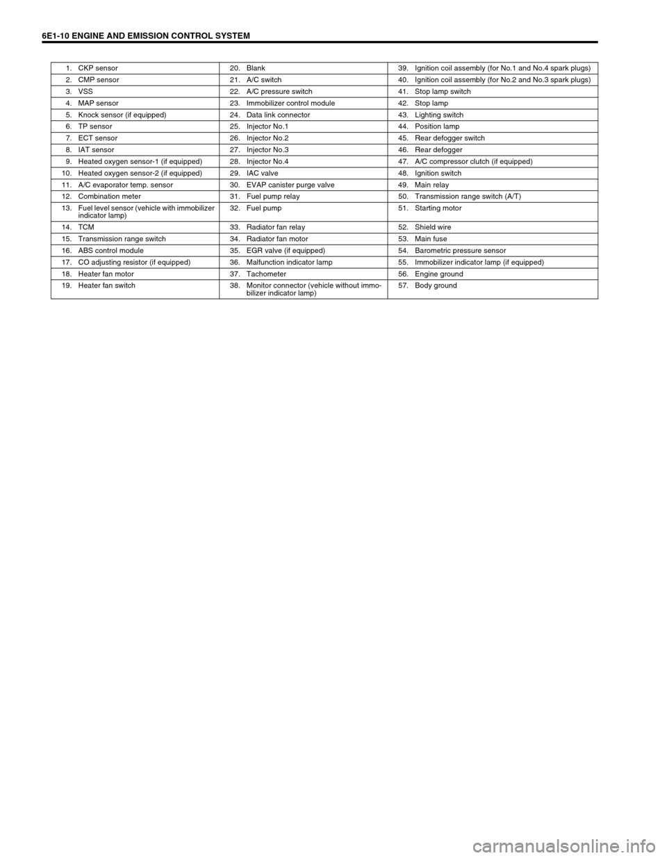
1. CKP sensor 20. Blank 39. Ignition coil assembly (for No.1 and No.4 spark plugs)
2. CMP sensor 21. A/C switch 40. Ignition coil assembly (for No.2 and No.3 spark plugs)
3. VSS 22. A/C pressure switch 41. Stop lamp switch
4. MAP sensor 23. Immobilizer control module 42. Stop lamp
5. Knock sensor (if equipped) 24. Data link connector 43. Lighting switch
6. TP sensor 25. Injector No.1 44. Position lamp
7. ECT sensor 26. Injector No.2 45. Rear defogger switch
8. IAT sensor 27. Injector No.3 46. Rear defogger
9. Heated oxygen sensor-1 (if equipped) 28. Injector No.4 47. A/C compressor clutch (if equipped)
10. Heated oxygen sensor-2 (if equipped) 29. IAC valve 48. Ignition switch
11. A/C evaporator temp. sensor 30. EVAP canister purge valve 49. Main relay
12. Combination meter 31. Fuel pump relay 50. Transmission range switch (A/T)
13. Fuel level sensor (vehicle with immobilizer
indicator lamp)32. Fuel pump 51. Starting motor
14. TCM 33. Radiator fan relay 52. Shield wire
15. Transmission range switch 34. Radiator fan motor 53. Main fuse
16. ABS control module 35. EGR valve (if equipped) 54. Barometric pressure sensor
17. CO adjusting resistor (if equipped) 36. Malfunction indicator lamp 55. Immobilizer indicator lamp (if equipped)
18. Heater fan motor 37. Tachometer 56. Engine ground
19. Heater fan switch 38. Monitor connector (vehicle without immo-
bilizer indicator lamp)57. Body ground
Page 633 of 698

6E1-12 ENGINE AND EMISSION CONTROL SYSTEM
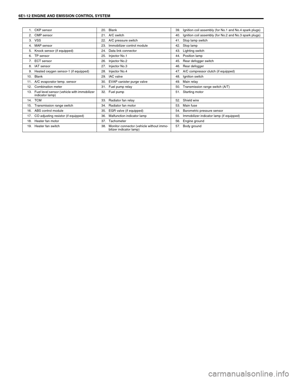
1. CKP sensor 20. Blank 39. Ignition coil assembly (for No.1 and No.4 spark plugs)
2. CMP sensor 21. A/C switch 40. Ignition coil assembly (for No.2 and No.3 spark plugs)
3. VSS 22. A/C pressure switch 41. Stop lamp switch
4. MAP sensor 23. Immobilizer control module 42. Stop lamp
5. Knock sensor (if equipped) 24. Data link connector 43. Lighting switch
6. TP sensor 25. Injector No.1 44. Position lamp
7. ECT sensor 26. Injector No.2 45. Rear defogger switch
8. IAT sensor 27. Injector No.3 46. Rear defogger
9. Heated oxygen sensor-1 (if equipped) 28. Injector No.4 47. A/C compressor clutch (if equipped)
10. Blank 29. IAC valve 48. Ignition switch
11. A/C evaporator temp. sensor 30. EVAP canister purge valve 49. Main relay
12. Combination meter 31. Fuel pump relay 50. Transmission range switch (A/T)
13. Fuel level sensor (vehicle with immobilizer
indicator lamp)32. Fuel pump 51. Starting motor
14. TCM 33. Radiator fan relay 52. Shield wire
15. Transmission range switch 34. Radiator fan motor 53. Main fuse
16. ABS control module 35. EGR valve (if equipped) 54. Barometric pressure sensor
17. CO adjusting resistor (if equipped) 36. Malfunction indicator lamp 55. Immobilizer indicator lamp (if equipped)
18. Heater fan motor 37. Tachometer 56. Engine ground
19. Heater fan switch 38. Monitor connector (vehicle without immo-
bilizer indicator lamp)57. Body ground
Page 636 of 698

ENGINE AND EMISSION CONTROL SYSTEM 6E1-15
ON-VEHICLE SERVICE
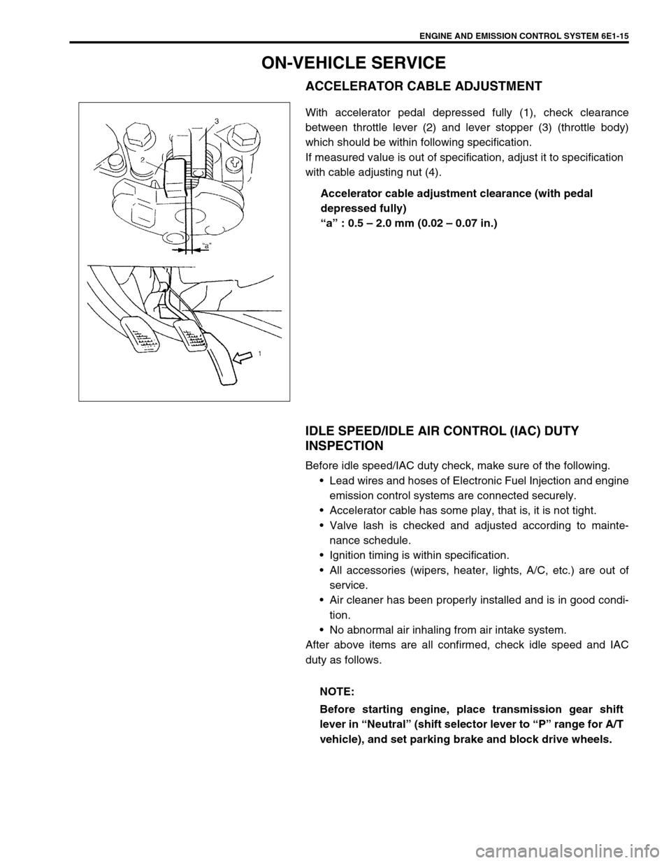
ACCELERATOR CABLE ADJUSTMENT
With accelerator pedal depressed fully (1), check clearance
between throttle lever (2) and lever stopper (3) (throttle body)
which should be within following specification.
If measured value is out of specification, adjust it to specification
with cable adjusting nut (4).
Accelerator cable adjustment clearance (with pedal
depressed fully)
“a” : 0.5 – 2.0 mm (0.02 – 0.07 in.)
IDLE SPEED/IDLE AIR CONTROL (IAC) DUTY
INSPECTION
Before idle speed/IAC duty check, make sure of the following.
Lead wires and hoses of Electronic Fuel Injection and engine
emission control systems are connected securely.
Accelerator cable has some play, that is, it is not tight.
Valve lash is checked and adjusted according to mainte-
nance schedule.
Ignition timing is within specification.
All accessories (wipers, heater, lights, A/C, etc.) are out of
service.
Air cleaner has been properly installed and is in good condi-
tion.
No abnormal air inhaling from air intake system.
After above items are all confirmed, check idle speed and IAC
duty as follows.
NOTE:
Before starting engine, place transmission gear shift
lever in “Neutral” (shift selector lever to “P” range for A/T
vehicle), and set parking brake and block drive wheels.