weight SUZUKI SWIFT 2000 1.G RG413 Service Workshop Manual
[x] Cancel search | Manufacturer: SUZUKI, Model Year: 2000, Model line: SWIFT, Model: SUZUKI SWIFT 2000 1.GPages: 698, PDF Size: 16.01 MB
Page 114 of 698

STEERING, SUSPENSION, WHEELS AND TIRES 3-5
TIRE DIAGNOSIS
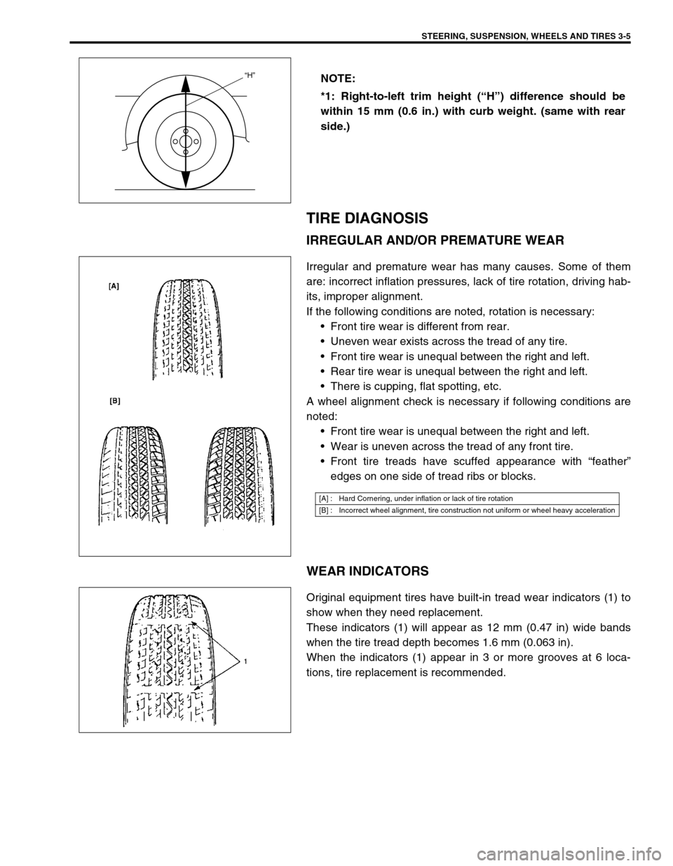
IRREGULAR AND/OR PREMATURE WEAR
Irregular and premature wear has many causes. Some of them
are: incorrect inflation pressures, lack of tire rotation, driving hab-
its, improper alignment.
If the following conditions are noted, rotation is necessary:
Front tire wear is different from rear.
Uneven wear exists across the tread of any tire.
Front tire wear is unequal between the right and left.
Rear tire wear is unequal between the right and left.
There is cupping, flat spotting, etc.
A wheel alignment check is necessary if following conditions are
noted:
Front tire wear is unequal between the right and left.
Wear is uneven across the tread of any front tire.
Front tire treads have scuffed appearance with “feather”
edges on one side of tread ribs or blocks.
WEAR INDICATORS
Original equipment tires have built-in tread wear indicators (1) to
show when they need replacement.
These indicators (1) will appear as 12 mm (0.47 in) wide bands
when the tire tread depth becomes 1.6 mm (0.063 in).
When the indicators (1) appear in 3 or more grooves at 6 loca-
tions, tire replacement is recommended.NOTE:
*1: Right-to-left trim height (“H”) difference should be
within 15 mm (0.6 in.) with curb weight. (same with rear
side.)
“H”
[A] : Hard Cornering, under inflation or lack of tire rotation
[B] : Incorrect wheel alignment, tire construction not uniform or wheel heavy acceleration
Page 248 of 698

WHEELS AND TIRES 3F-3
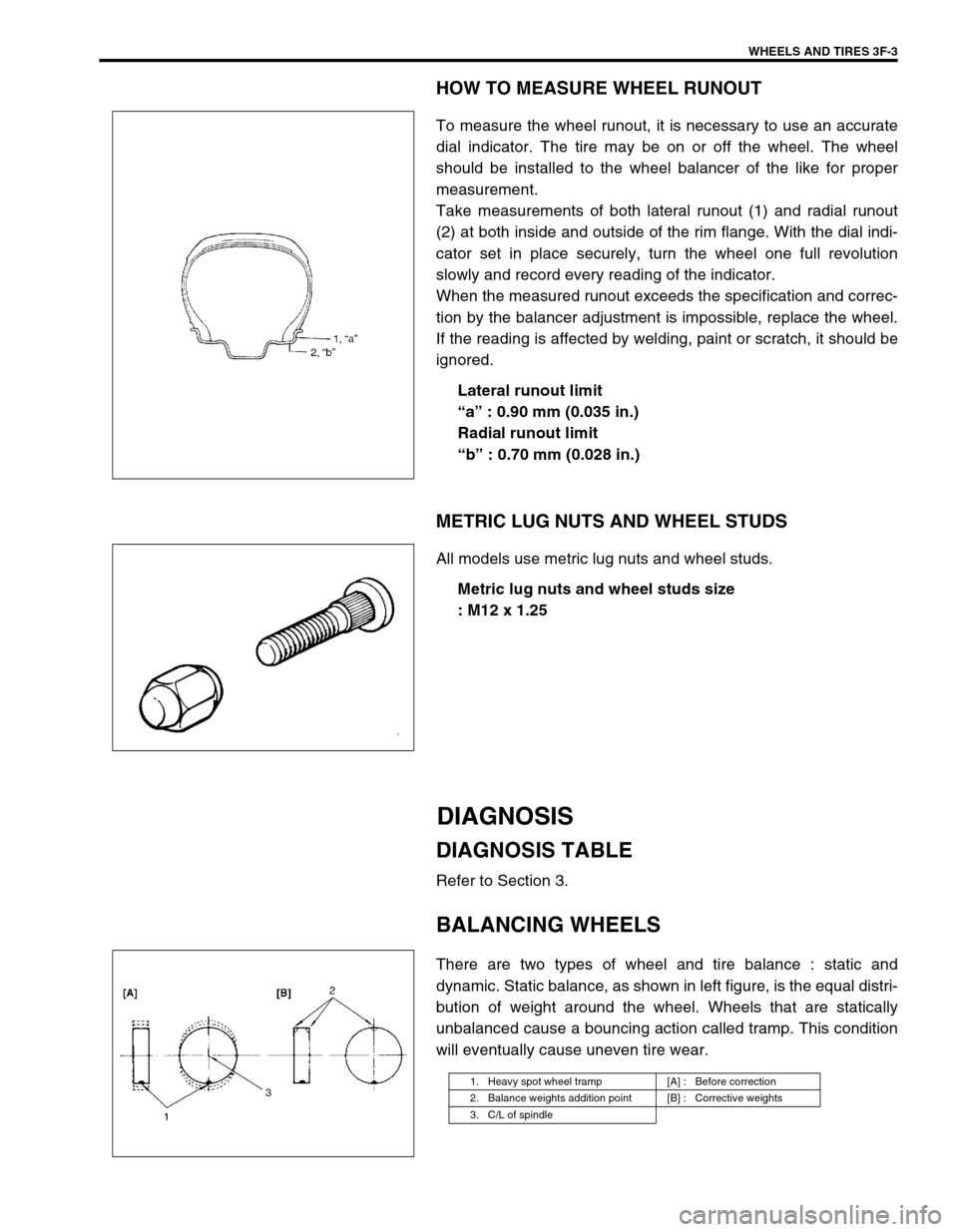
HOW TO MEASURE WHEEL RUNOUT
To measure the wheel runout, it is necessary to use an accurate
dial indicator. The tire may be on or off the wheel. The wheel
should be installed to the wheel balancer of the like for proper
measurement.
Take measurements of both lateral runout (1) and radial runout
(2) at both inside and outside of the rim flange. With the dial indi-
cator set in place securely, turn the wheel one full revolution
slowly and record every reading of the indicator.
When the measured runout exceeds the specification and correc-
tion by the balancer adjustment is impossible, replace the wheel.
If the reading is affected by welding, paint or scratch, it should be
ignored.
Lateral runout limit
“a” : 0.90 mm (0.035 in.)
Radial runout limit
“b” : 0.70 mm (0.028 in.)
METRIC LUG NUTS AND WHEEL STUDS
All models use metric lug nuts and wheel studs.
Metric lug nuts and wheel studs size
: M12 x 1.25
DIAGNOSIS
DIAGNOSIS TABLE
Refer to Section 3.
BALANCING WHEELS
There are two types of wheel and tire balance : static and
dynamic. Static balance, as shown in left figure, is the equal distri-
bution of weight around the wheel. Wheels that are statically
unbalanced cause a bouncing action called tramp. This condition
will eventually cause uneven tire wear.
1. Heavy spot wheel tramp [A] : Before correction
2. Balance weights addition point [B] : Corrective weights
3. C/L of spindle
Page 249 of 698

3F-4 WHEELS AND TIRES
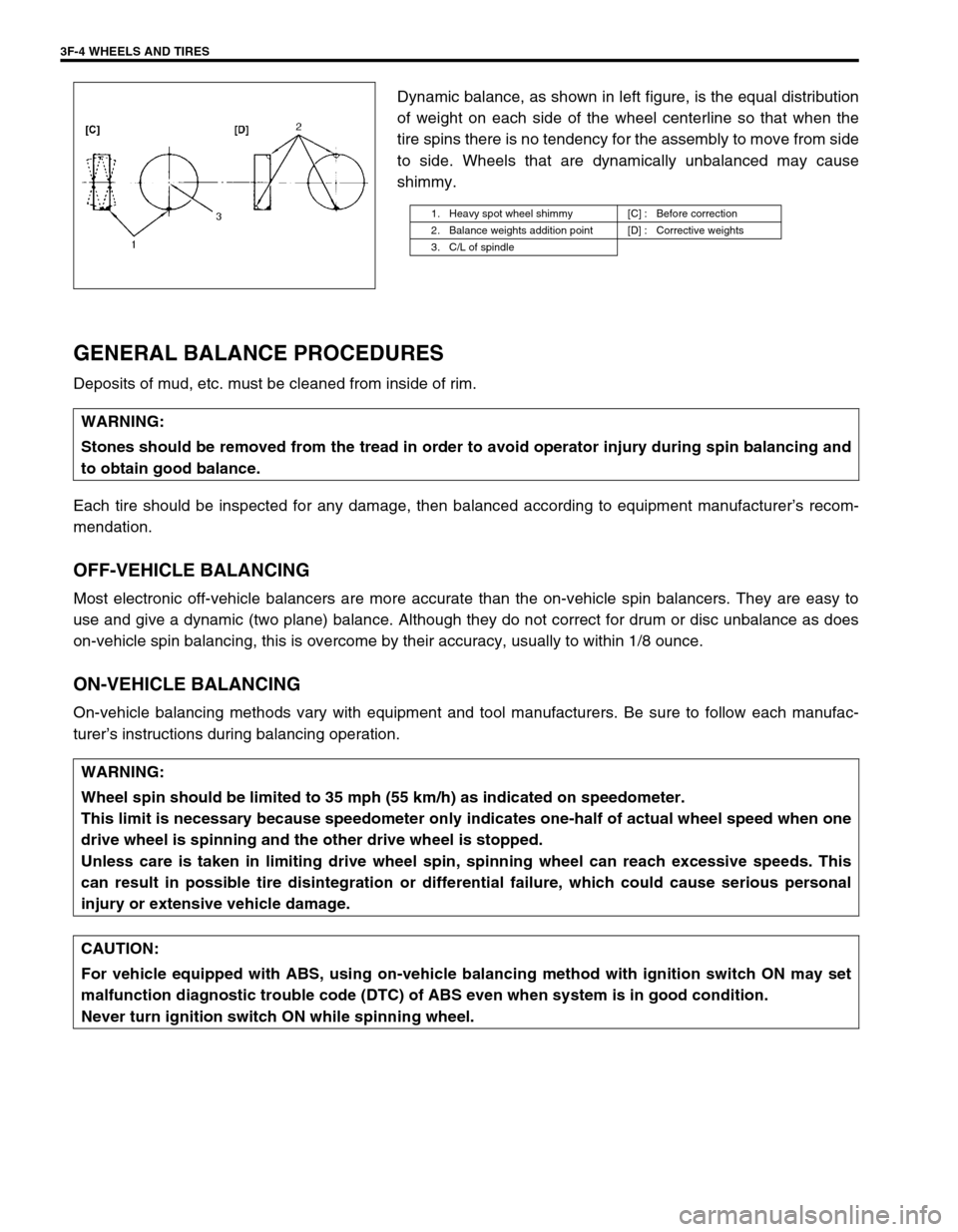
Dynamic balance, as shown in left figure, is the equal distribution
of weight on each side of the wheel centerline so that when the
tire spins there is no tendency for the assembly to move from side
to side. Wheels that are dynamically unbalanced may cause
shimmy.
GENERAL BALANCE PROCEDURES
Deposits of mud, etc. must be cleaned from inside of rim.
Each tire should be inspected for any damage, then balanced according to equipment manufacturer’s recom-
mendation.
OFF-VEHICLE BALANCING
Most electronic off-vehicle balancers are more accurate than the on-vehicle spin balancers. They are easy to
use and give a dynamic (two plane) balance. Although they do not correct for drum or disc unbalance as does
on-vehicle spin balancing, this is overcome by their accuracy, usually to within 1/8 ounce.
ON-VEHICLE BALANCING
On-vehicle balancing methods vary with equipment and tool manufacturers. Be sure to follow each manufac-
turer’s instructions during balancing operation.
1. Heavy spot wheel shimmy [C] : Before correction
2. Balance weights addition point [D] : Corrective weights
3. C/L of spindle
WARNING:
Stones should be removed from the tread in order to avoid operator injury during spin balancing and
to obtain good balance.
WARNING:
Wheel spin should be limited to 35 mph (55 km/h) as indicated on speedometer.
This limit is necessary because speedometer only indicates one-half of actual wheel speed when one
drive wheel is spinning and the other drive wheel is stopped.
Unless care is taken in limiting drive wheel spin, spinning wheel can reach excessive speeds. This
can result in possible tire disintegration or differential failure, which could cause serious personal
injury or extensive vehicle damage.
CAUTION:
For vehicle equipped with ABS, using on-vehicle balancing method with ignition switch ON may set
malfunction diagnostic trouble code (DTC) of ABS even when system is in good condition.
Never turn ignition switch ON while spinning wheel.
Page 286 of 698

BRAKES 5-13
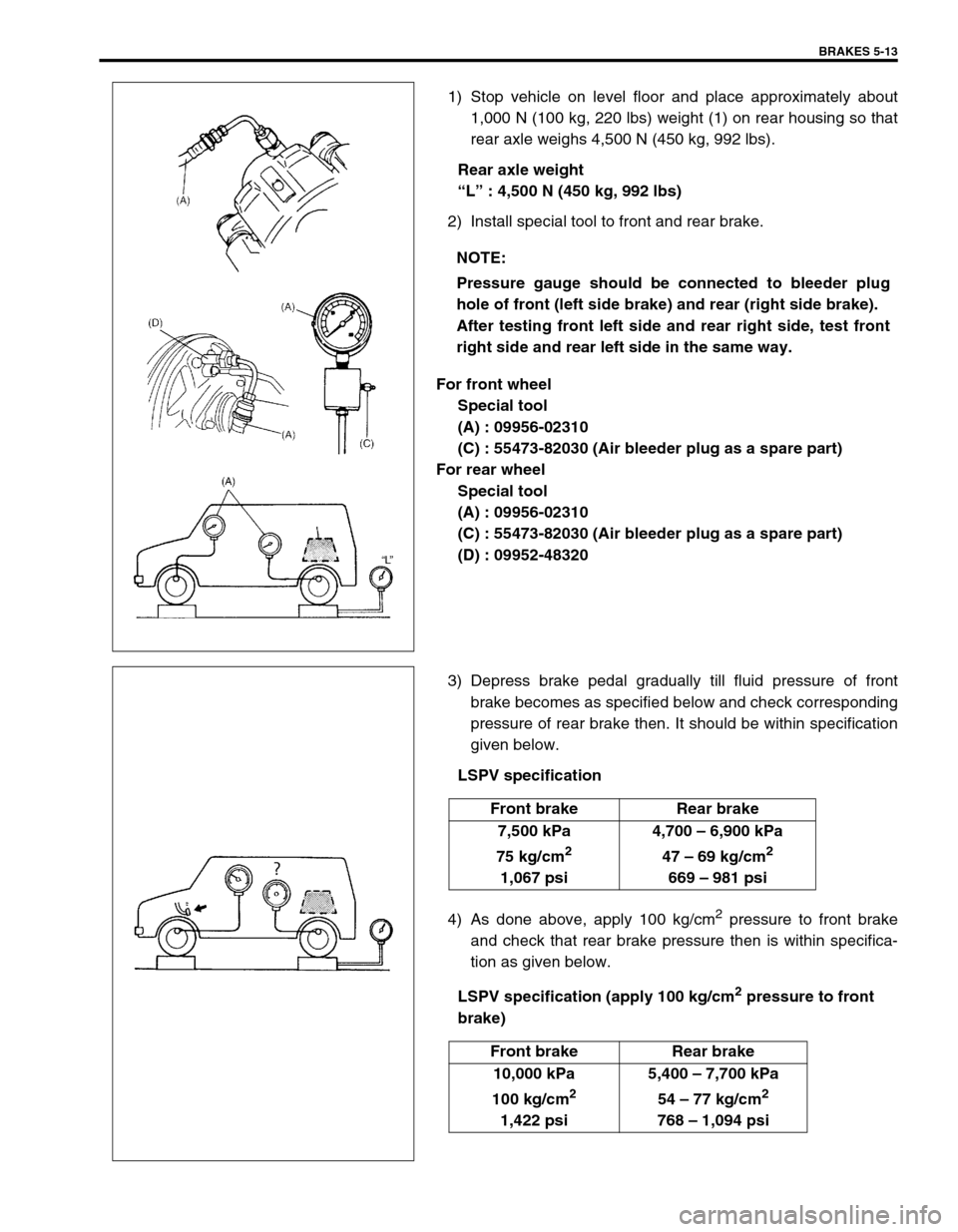
1) Stop vehicle on level floor and place approximately about
1,000 N (100 kg, 220 lbs) weight (1) on rear housing so that
rear axle weighs 4,500 N (450 kg, 992 lbs).
Rear axle weight
“L” : 4,500 N (450 kg, 992 lbs)
2) Install special tool to front and rear brake.
For front wheel
Special tool
(A) : 09956-02310
(C) : 55473-82030 (Air bleeder plug as a spare part)
For rear wheel
Special tool
(A) : 09956-02310
(C) : 55473-82030 (Air bleeder plug as a spare part)
(D) : 09952-48320
3) Depress brake pedal gradually till fluid pressure of front
brake becomes as specified below and check corresponding
pressure of rear brake then. It should be within specification
given below.
LSPV specification
4) As done above, apply 100 kg/cm
2 pressure to front brake
and check that rear brake pressure then is within specifica-
tion as given below.
LSPV specification (apply 100 kg/cm
2 pressure to front
brake) NOTE:
Pressure gauge should be connected to bleeder plug
hole of front (left side brake) and rear (right side brake).
After testing front left side and rear right side, test front
right side and rear left side in the same way.
Front brake Rear brake
7,500 kPa
75 kg/cm
2
1,067 psi4,700 – 6,900 kPa
47 – 69 kg/cm
2
669 – 981 psi
Front brake Rear brake
10,000 kPa
100 kg/cm
2
1,422 psi5,400 – 7,700 kPa
54 – 77 kg/cm
2
768 – 1,094 psi