warning light SUZUKI SWIFT 2000 1.G RG413 Service Owner's Manual
[x] Cancel search | Manufacturer: SUZUKI, Model Year: 2000, Model line: SWIFT, Model: SUZUKI SWIFT 2000 1.GPages: 698, PDF Size: 16.01 MB
Page 339 of 698

5E-14 ANTILOCK BRAKE SYSTEM (ABS)
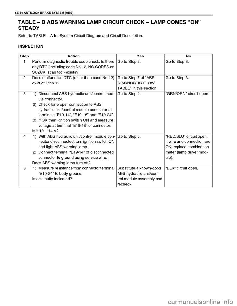
TABLE – B ABS WARNING LAMP CIRCUIT CHECK – LAMP COMES “ON”
STEADY
Refer to TABLE – A for System Circuit Diagram and Circuit Description.
INSPECTION
Step Action Yes No
1 Perform diagnostic trouble code check. Is there
any DTC (including code No.12, NO CODES on
SUZUKI scan tool) exists?Go to Step 2. Go to Step 3.
2 Does malfunction DTC (other than code No.12)
exist at Step 1?Go to Step 7 of “ABS
DIAGNOSTIC FLOW
TABLE” in this section.Go to Step 3.
3 1) Disconnect ABS hydraulic unit/control mod-
ule connector.
2) Check for proper connection to ABS
hydraulic unit/control module connector at
terminals “E19-14”, “E19-18” and “E19-24”.
3) If OK then ignition switch ON and measure
voltage at terminal “E19-18” of connector.
Is it 10 – 14 V?Go to Step 4.“GRN/ORN” circuit open.
4 1) With ABS hydraulic unit/control module con-
nector disconnected, turn ignition switch ON
and light ABS warning lamp.
2) Connect terminal “E19-14” of disconnected
connector to ground using service wire.
Does ABS warning lamp turn off?Go to Step 5.“RED/BLU” circuit open.
If wire and connection are
OK, replace combination
meter (lamp driver mod-
ule).
5 1) Measure resistance from connector terminal
“E19-24” to body ground.
Is continuity indicated?Substitute a known-good
ABS hydraulic unit/con-
trol module assembly and
recheck.“BLK” circuit open.
Page 401 of 698

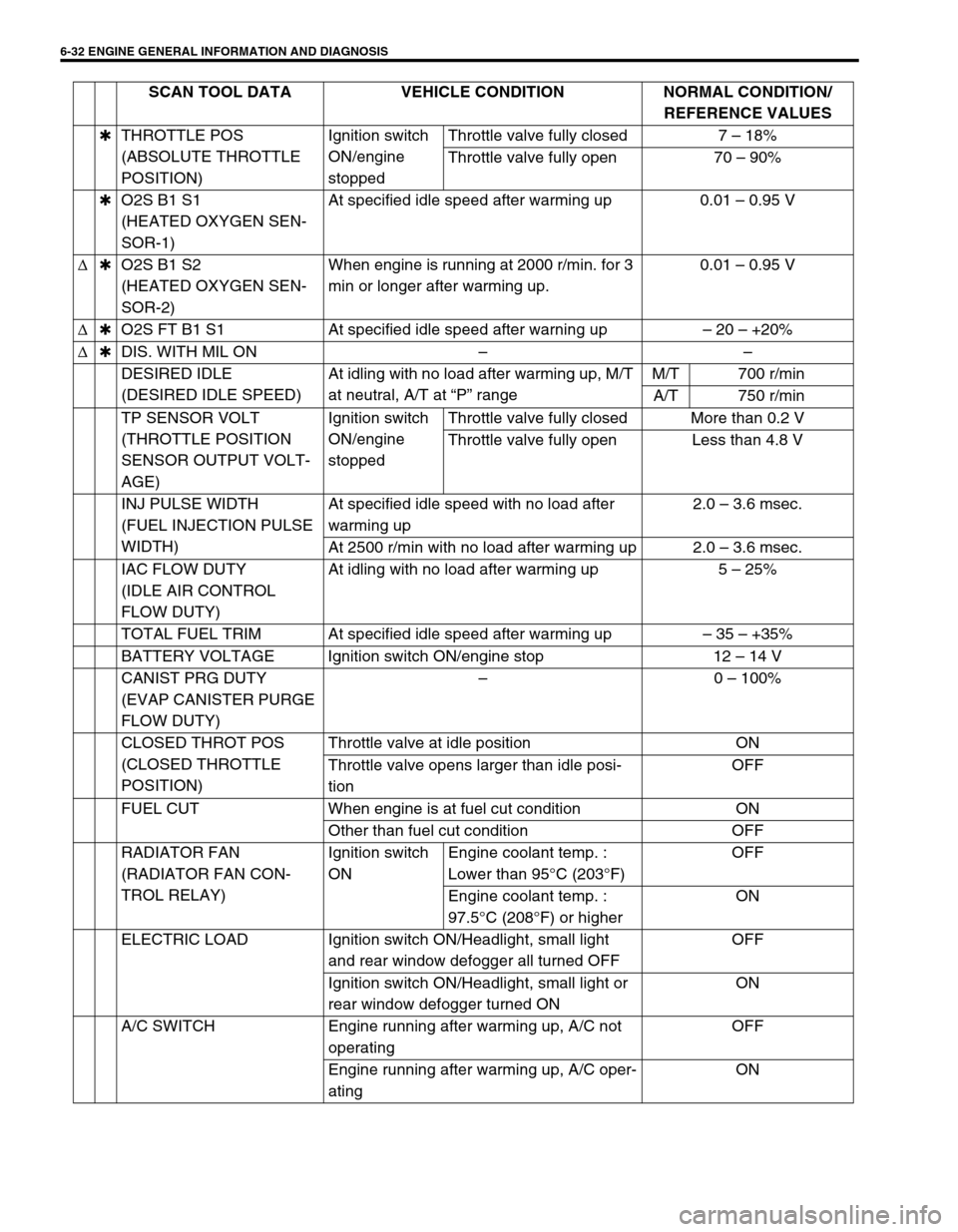
6-32 ENGINE GENERAL INFORMATION AND DIAGNOSIS
✱THROTTLE POS
(ABSOLUTE THROTTLE
POSITION)Ignition switch
ON/engine
stoppedThrottle valve fully closed 7 – 18%
Throttle valve fully open 70 – 90%
✱O2S B1 S1
(HEATED OXYGEN SEN-
SOR-1)At specified idle speed after warming up 0.01 – 0.95 V
∆✱O2S B1 S2
(HEATED OXYGEN SEN-
SOR-2)When engine is running at 2000 r/min. for 3
min or longer after warming up.0.01 – 0.95 V
∆✱O2S FT B1 S1 At specified idle speed after warning up– 20 – +20%
∆✱DIS. WITH MIL ON––
DESIRED IDLE
(DESIRED IDLE SPEED)At idling with no load after warming up, M/T
at neutral, A/T at “P” rangeM/T 700 r/min
A/T 750 r/min
TP SENSOR VOLT
(THROTTLE POSITION
SENSOR OUTPUT VOLT-
AGE)Ignition switch
ON/engine
stoppedThrottle valve fully closed More than 0.2 V
Throttle valve fully open Less than 4.8 V
INJ PULSE WIDTH
(FUEL INJECTION PULSE
WIDTH)At specified idle speed with no load after
warming up2.0 – 3.6 msec.
At 2500 r/min with no load after warming up 2.0 – 3.6 msec.
IAC FLOW DUTY
(IDLE AIR CONTROL
FLOW DUTY)At idling with no load after warming up 5 – 25%
TOTAL FUEL TRIM At specified idle speed after warming up– 35 – +35%
BATTERY VOLTAGE Ignition switch ON/engine stop 12 – 14 V
CANIST PRG DUTY
(EVAP CANISTER PURGE
FLOW DUTY)–0 – 100%
CLOSED THROT POS
(CLOSED THROTTLE
POSITION)Throttle valve at idle position ON
Throttle valve opens larger than idle posi-
tionOFF
FUEL CUT When engine is at fuel cut condition ON
Other than fuel cut condition OFF
RADIATOR FAN
(RADIATOR FAN CON-
TROL RELAY)Ignition switch
ONEngine coolant temp. :
Lower than 95°C (203°F)OFF
Engine coolant temp. :
97.5°C (208°F) or higherON
ELECTRIC LOAD Ignition switch ON/Headlight, small light
and rear window defogger all turned OFFOFF
Ignition switch ON/Headlight, small light or
rear window defogger turned ONON
A/C SWITCH Engine running after warming up, A/C not
operatingOFF
Engine running after warming up, A/C oper-
atingON SCAN TOOL DATA VEHICLE CONDITION NORMAL CONDITION/
REFERENCE VALUES
Page 415 of 698

6-46 ENGINE GENERAL INFORMATION AND DIAGNOSIS
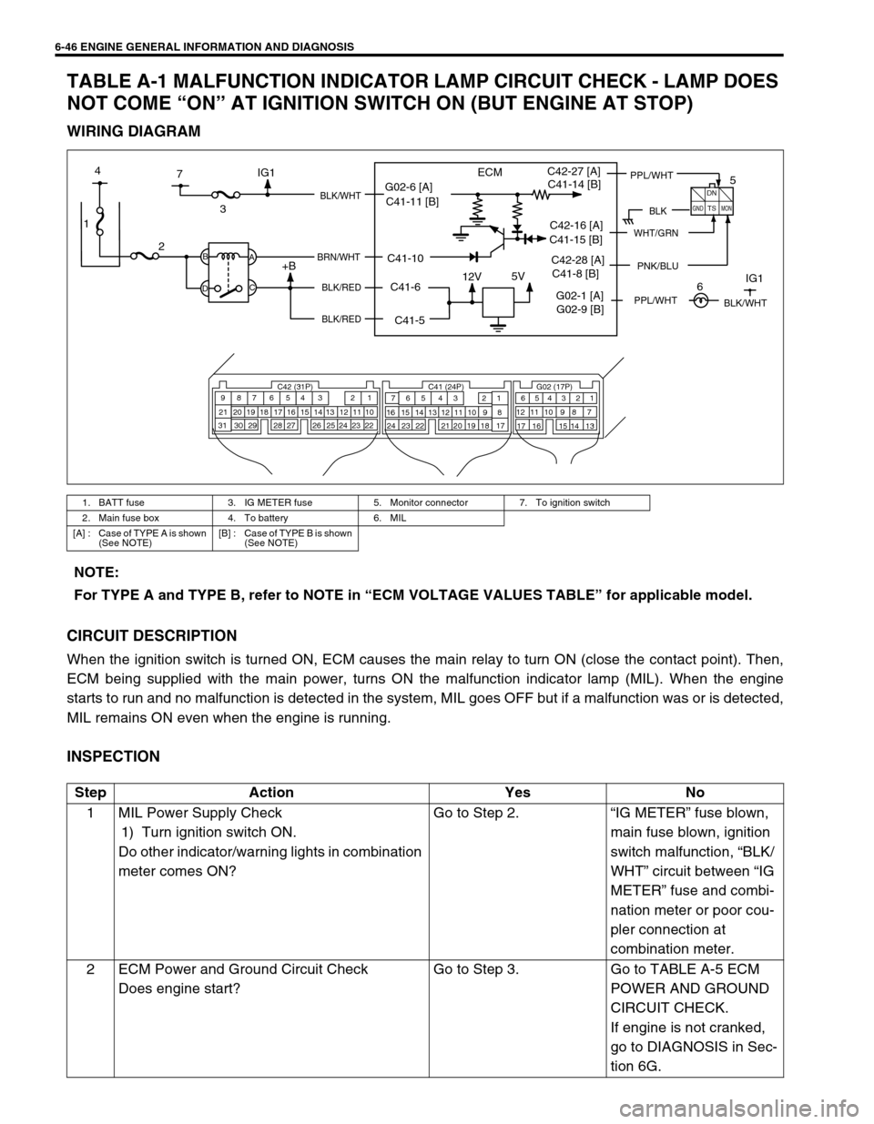
TABLE A-1 MALFUNCTION INDICATOR LAMP CIRCUIT CHECK - LAMP DOES
NOT COME “ON” AT IGNITION SWITCH ON (BUT ENGINE AT STOP)
WIRING DIAGRAM
CIRCUIT DESCRIPTION
When the ignition switch is turned ON, ECM causes the main relay to turn ON (close the contact point). Then,
ECM being supplied with the main power, turns ON the malfunction indicator lamp (MIL). When the engine
starts to run and no malfunction is detected in the system, MIL goes OFF but if a malfunction was or is detected,
MIL remains ON even when the engine is running.
INSPECTION
1. BATT fuse 3. IG METER fuse 5. Monitor connector 7. To ignition switch
2. Main fuse box 4. To battery 6. MIL
[A] : Case of TYPE A is shown
(See NOTE)[B] : Case of TYPE B is shown
(See NOTE)
1
12V5V
ECM
23
+BB
DA
C
BLK/WHT
BRN/WHT
BLK/RED
BLK/RED
C42 (31P) C41 (24P) G02 (17P)1 2 3 4 5 6 7 8 9
10 11 12 13 14 15 16 17 18 19 20 21
22 23 24 25 26 28 27 29 30 315 6
1 2 3 4 5 6 7
11 12
9 10 11 13 12 14 15 16
16 171 2
7 8
13 14 3 4
9 10
15 17 188
19 20 21 22 23 24
BLK
DN
TS
GNDMON
PPL/WHTC42-27 [A]
C42-16 [A]
PNK/BLUC42-28 [A]
7 4
G02-1 [A]IG1
5
6IG1
WHT/GRN
BLK/WHT
G02-6 [A]
C41-5 C41-6 C41-10 C41-11 [B]C41-14 [B]
C41-15 [B]
C41-8 [B]
G02-9 [B]
PPL/WHT
NOTE:
For TYPE A and TYPE B, refer to NOTE in “ECM VOLTAGE VALUES TABLE” for applicable model.
Step Action Yes No
1 MIL Power Supply Check
1) Turn ignition switch ON.
Do other indicator/warning lights in combination
meter comes ON?Go to Step 2.“IG METER” fuse blown,
main fuse blown, ignition
switch malfunction, “BLK/
WHT” circuit between “IG
METER” fuse and combi-
nation meter or poor cou-
pler connection at
combination meter.
2 ECM Power and Ground Circuit Check
Does engine start?Go to Step 3. Go to TABLE A-5 ECM
POWER AND GROUND
CIRCUIT CHECK.
If engine is not cranked,
go to DIAGNOSIS in Sec-
tion 6G.
Page 689 of 698

CHARGING SYSTEM 6H-9
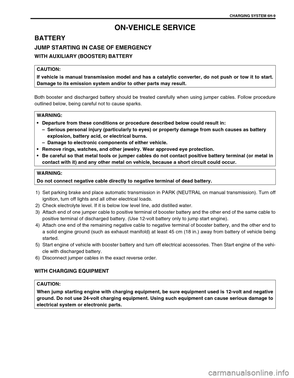
ON-VEHICLE SERVICE
BATTERY
JUMP STARTING IN CASE OF EMERGENCY
WITH AUXILIARY (BOOSTER) BATTERY
Both booster and discharged battery should be treated carefully when using jumper cables. Follow procedure
outlined below, being careful not to cause sparks.
1) Set parking brake and place automatic transmission in PARK (NEUTRAL on manual transmission). Turn off
ignition, turn off lights and all other electrical loads.
2) Check electrolyte level. If it is below low level line, add distilled water.
3) Attach end of one jumper cable to positive terminal of booster battery and the other end of the same cable to
positive terminal of discharged battery. (Use 12-volt battery only to jump start engine).
4) Attach one end of the remaining negative cable to negative terminal of booster battery, and the other end to
a solid engine ground (such as exhaust manifold) at least 45 cm (18 in.) away from battery of vehicle being
started.
5) Start engine of vehicle with booster battery and turn off electrical accessories. Then Start engine of the vehi-
cle with discharged battery.
6) Disconnect jumper cables in the exact reverse order.
WITH CHARGING EQUIPMENT
CAUTION:
If vehicle is manual transmission model and has a catalytic converter, do not push or tow it to start.
Damage to its emission system and/or to other parts may result.
WARNING:
Departure from these conditions or procedure described below could result in:
–Serious personal injury (particularly to eyes) or property damage from such causes as battery
explosion, battery acid, or electrical burns.
–Damage to electronic components of either vehicle.
Remove rings, watches, and other jewelry. Wear approved eye protection.
Be careful so that metal tools or jumper cables do not contact positive battery terminal (or metal in
contact with it) and any other metal on vehicle, because a short circuit could occur.
WARNING:
Do not connect negative cable directly to negative terminal of dead battery.
CAUTION:
When jump starting engine with charging equipment, be sure equipment used is 12-volt and negative
ground. Do not use 24-volt charging equipment. Using such equipment can cause serious damage to
electrical system or electronic parts.