wheel SUZUKI SWIFT 2000 1.G RG413 Service Owner's Manual
[x] Cancel search | Manufacturer: SUZUKI, Model Year: 2000, Model line: SWIFT, Model: SUZUKI SWIFT 2000 1.GPages: 698, PDF Size: 16.01 MB
Page 114 of 698
STEERING, SUSPENSION, WHEELS AND TIRES 3-5
TIRE DIAGNOSIS
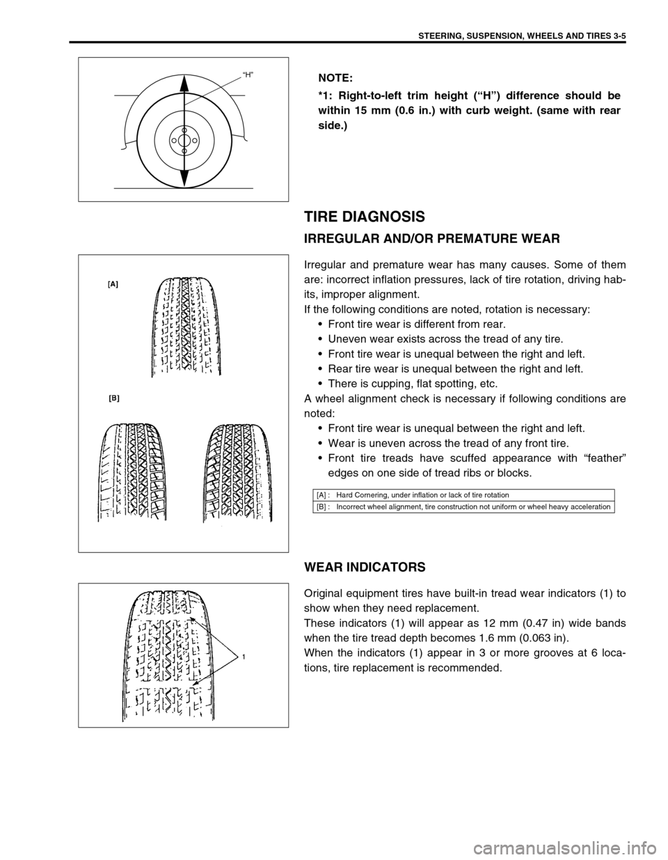
IRREGULAR AND/OR PREMATURE WEAR
Irregular and premature wear has many causes. Some of them
are: incorrect inflation pressures, lack of tire rotation, driving hab-
its, improper alignment.
If the following conditions are noted, rotation is necessary:
Front tire wear is different from rear.
Uneven wear exists across the tread of any tire.
Front tire wear is unequal between the right and left.
Rear tire wear is unequal between the right and left.
There is cupping, flat spotting, etc.
A wheel alignment check is necessary if following conditions are
noted:
Front tire wear is unequal between the right and left.
Wear is uneven across the tread of any front tire.
Front tire treads have scuffed appearance with “feather”
edges on one side of tread ribs or blocks.
WEAR INDICATORS
Original equipment tires have built-in tread wear indicators (1) to
show when they need replacement.
These indicators (1) will appear as 12 mm (0.47 in) wide bands
when the tire tread depth becomes 1.6 mm (0.063 in).
When the indicators (1) appear in 3 or more grooves at 6 loca-
tions, tire replacement is recommended.NOTE:
*1: Right-to-left trim height (“H”) difference should be
within 15 mm (0.6 in.) with curb weight. (same with rear
side.)
“H”
[A] : Hard Cornering, under inflation or lack of tire rotation
[B] : Incorrect wheel alignment, tire construction not uniform or wheel heavy acceleration
Page 115 of 698
3-6 STEERING, SUSPENSION, WHEELS AND TIRES
RADIAL TIRE WADDLE
Waddle is side to side movement at the front and/or rear of the
vehicle. It is caused by the steel belt not being straight within the
tire. It is most noticeable at a low speed, 8 to 48 kph (5 to 30
mph).
It is possible to locate the faulty tire by road testing the vehicle. If
it is on the rear, the rear end of the vehicle shakes from side to
side or “waddles”. To the driver in the seat, it feels as though
someone is pushing on the side of vehicle.
If the faulty tire is on the front, waddling is more visual. The front
sheet metal appears to be moving back and forth and the driver
feels as though he is at the pivot point in vehicle.
Waddle can be quickly diagnosed by using Tire Problem Detector
(TPD) and following the equipment manufacture’s recommenda-
tions.
If TPD is not available, an alternative method of substituting
known-good tire/wheel assemblies can be used as follows,
although it takes a longer time.
1) Ride vehicle to determine whether the front or rear waddles.
2) Install tires and wheels that are known to be good (on similar vehicle) in place of those on waddling end of
vehicle. If waddling end cannot be identified, substitute rear ones.
3) Road test again. If improvement is noted, reinstall originals one at a time till waddle causal tire is found. If no
improvement is noted, install known-good tires in place of all four. Then reinstall originals in the same man-
ner as above.
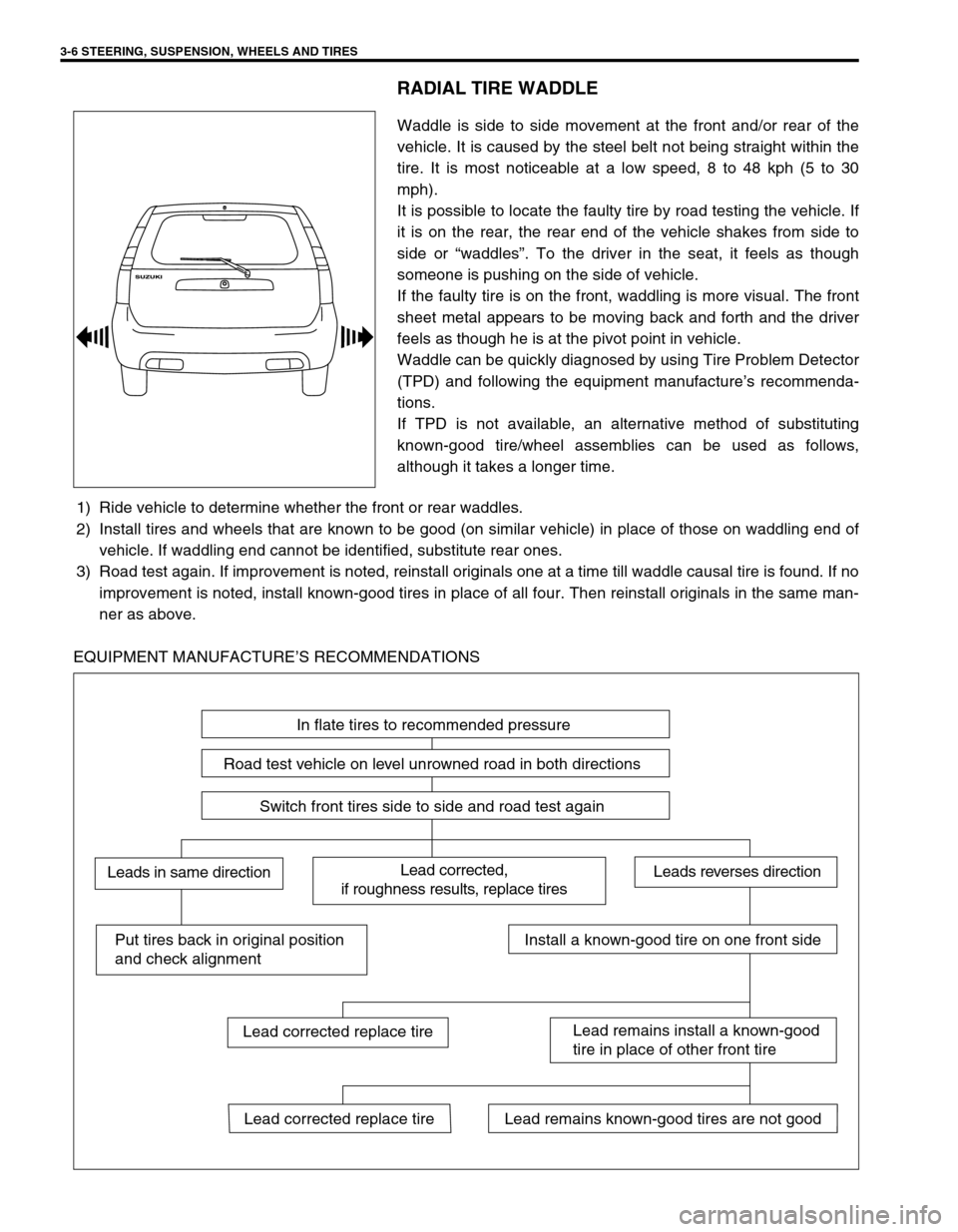
EQUIPMENT MANUFACTURE’S RECOMMENDATIONS
In flate tires to recommended pressure
Road test vehicle on level unrowned road in both directions
Switch front tires side to side and road test again
Lead corrected,
if roughness results, replace tiresLeads in same directionLeads reverses direction
Put tires back in original position
and check alignmentInstall a known-good tire on one front side
Lead remains install a known-good
tire in place of other front tire
Lead remains known-good tires are not goodLead corrected replace tire
Lead corrected replace tire
Page 116 of 698
STEERING, SUSPENSION, WHEELS AND TIRES 3-7
RADIAL TIRE LEAD
“Lead” is the deviation of the vehicle from a straight path on a level rod even with no pressure on the steering
wheel.
Lead is usually caused by:
Incorrect alignment.
Uneven brake adjustment.
Tire construction.
The way in which a tire is built can produce lead in a vehicle. An example of this is placement of the belt. Off
center belts on radial tires can cause the tire to develop a side force while rolling straight down the road. If one
side of the tire has a little larger diameter than the other, the tire will tend to roll to one side. This will develop a
side force which can produce vehicle lead.
The procedure in above figure (Lead Diagnosis) should be used to make sure that front alignment is not mis-
taken for tire lead.
Part of the lead diagnosis procedure is different from the proper tire rotation pattern currently in the owner
and service manuals. If a medium to high mileage tire is moved to the other side of the vehicle, be sure to
check that ride roughness has not developed
Rear tires will not cause lead.
VIBRATION DIAGNOSIS
Wheel unbalance causes most of the highway speed vibration problems. If a vibration remains after dynamic
balancing, its possible causes are as follows.
Tire runout.
Wheel runout.
Tire stiffness variation.
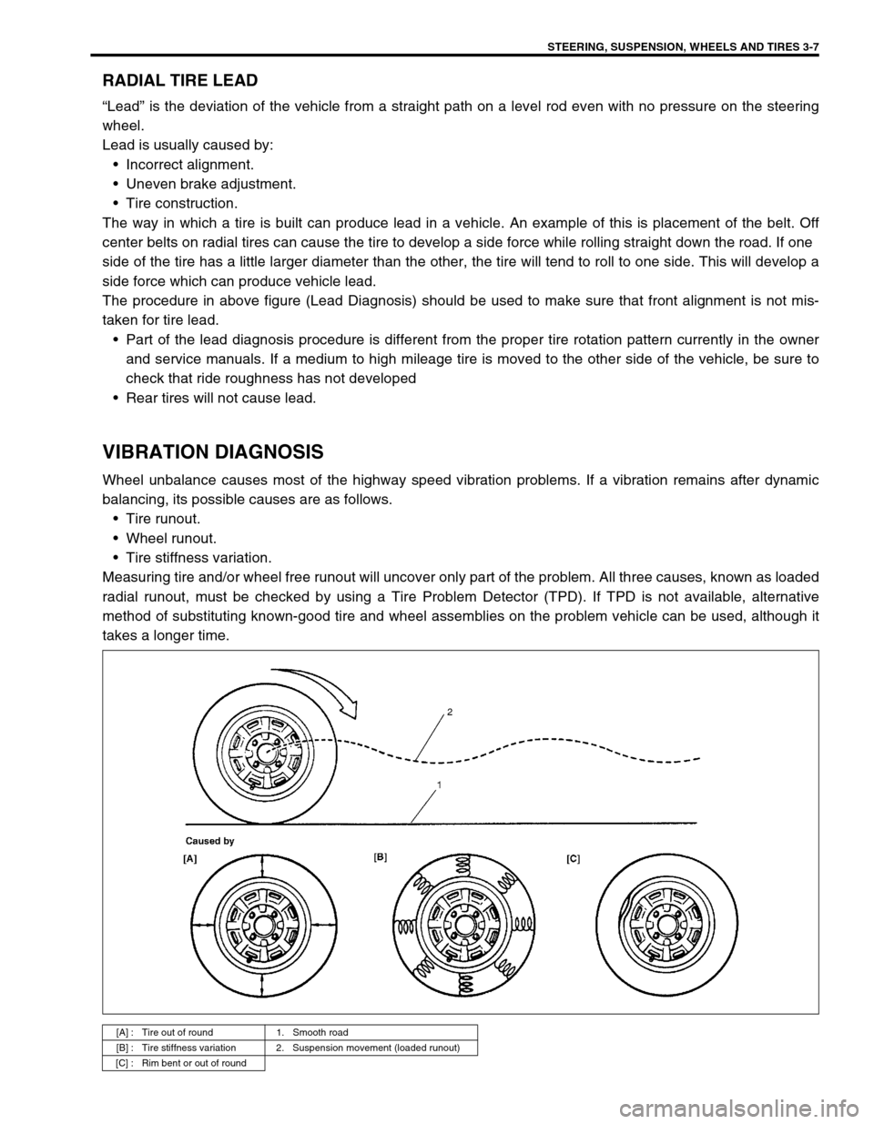
Measuring tire and/or wheel free runout will uncover only part of the problem. All three causes, known as loaded
radial runout, must be checked by using a Tire Problem Detector (TPD). If TPD is not available, alternative
method of substituting known-good tire and wheel assemblies on the problem vehicle can be used, although it
takes a longer time.
[A] : Tire out of round 1. Smooth road
[B] : Tire stiffness variation 2. Suspension movement (loaded runout)
[C] : Rim bent or out of round
Page 117 of 698

3-8 STEERING, SUSPENSION, WHEELS AND TIRES
Page 119 of 698
3A-2 FRONT END ALIGNMENT
GENERAL DESCRIPTION
Front alignment refers to the angular relationship between the
front wheels, the front suspension attaching parts and the ground.
Generally, the only adjustment required for front alignment is toe
setting.
Camber and caster can’t be adjusted. Therefore, should camber
or caster be out of specification due to the damage caused by
hazardous road conditions or collision, whether the damage is in
body or in suspension should be determined. If the body is dam-
aged, it should be repaired and if suspension is damaged, it
should be replaced.
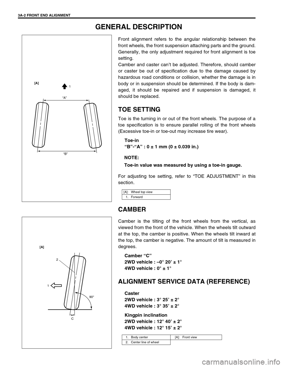
TOE SETTING
Toe is the turning in or out of the front wheels. The purpose of a
toe specification is to ensure parallel rolling of the front wheels
(Excessive toe-in or toe-out may increase tire wear).
Toe-in
“B”-“A” : 0 ± 1 mm (0 ± 0.039 in.)
For adjusting toe setting, refer to “TOE ADJUSTMENT” in this
section.
CAMBER
Camber is the tilting of the front wheels from the vertical, as
viewed from the front of the vehicle. When the wheels tilt outward
at the top, the camber is positive. When the wheels tilt inward at
the top, the camber is negative. The amount of tilt is measured in
degrees.
Camber “C”
2WD vehicle : –0° 20’ ± 1°
4WD vehicle : 0° ± 1°
ALIGNMENT SERVICE DATA (REFERENCE)
Caster
2WD vehicle : 3° 25’ ± 2°
4WD vehicle : 3° 35’ ± 2°
Kingpin inclination
2WD vehicle : 12° 40’ ± 2°
4WD vehicle : 12° 15’ ± 2° NOTE:
Toe-in value was measured by using a toe-in gauge.
[A]: Wheel top view
1. Forward
“A”
“B”1 [A]
1. Body center [A]: Front view
2. Center line of wheel
2
1
90
o
C [A]
Page 120 of 698
FRONT END ALIGNMENT 3A-3
DIAGNOSIS
DIAGNOSIS TABLE
For the details, refer to Section 3.
PRELIMINARY CHECKS PRIOR TO ADJUSTING FRONT ALIGNMENT
Steering and vibration complaints are not always the result of improper alignment. An additional item to be
checked is the possibility of tire lead due to worn or improperly manufactured tires. “Lead” is the deviation of the
vehicle from a straight path on a level road without hand pressure on the steering wheel. Procedure for deter-
mining the presence of a tire lead problem contains in SECTION 3. Before making any adjustment affecting toe
setting, the following checks and inspections should be made to ensure correctness of alignment readings and
alignment adjustments:
1) Check all tires for proper inflation pressures and approximately the same tread wear.
2) Check for loose of ball joints. Check tie rod ends; if excessive looseness is noted, it must be corrected
before adjusting.
3) Check for run-out of wheels and tires.
4) Check vehicle trim heights; if out of limits and a correction is to be made, it must be made before adjusting
toe.
5) Check for loose of suspension arms.
6) Check for loose or missing stabilizer bar attachments.
7) Consideration must be given to excess loads, such as tool boxes. If this excess load is normally carried in
vehicle, it should remain in vehicle during alignment checks.
8) Consider condition of equipment being used to check alignment and follow manufacturer's instructions.
9) Regardless of equipment used to check alignment, vehicle must be on a level surface both fore and aft and
transversely.
TOE ADJUSTMENT
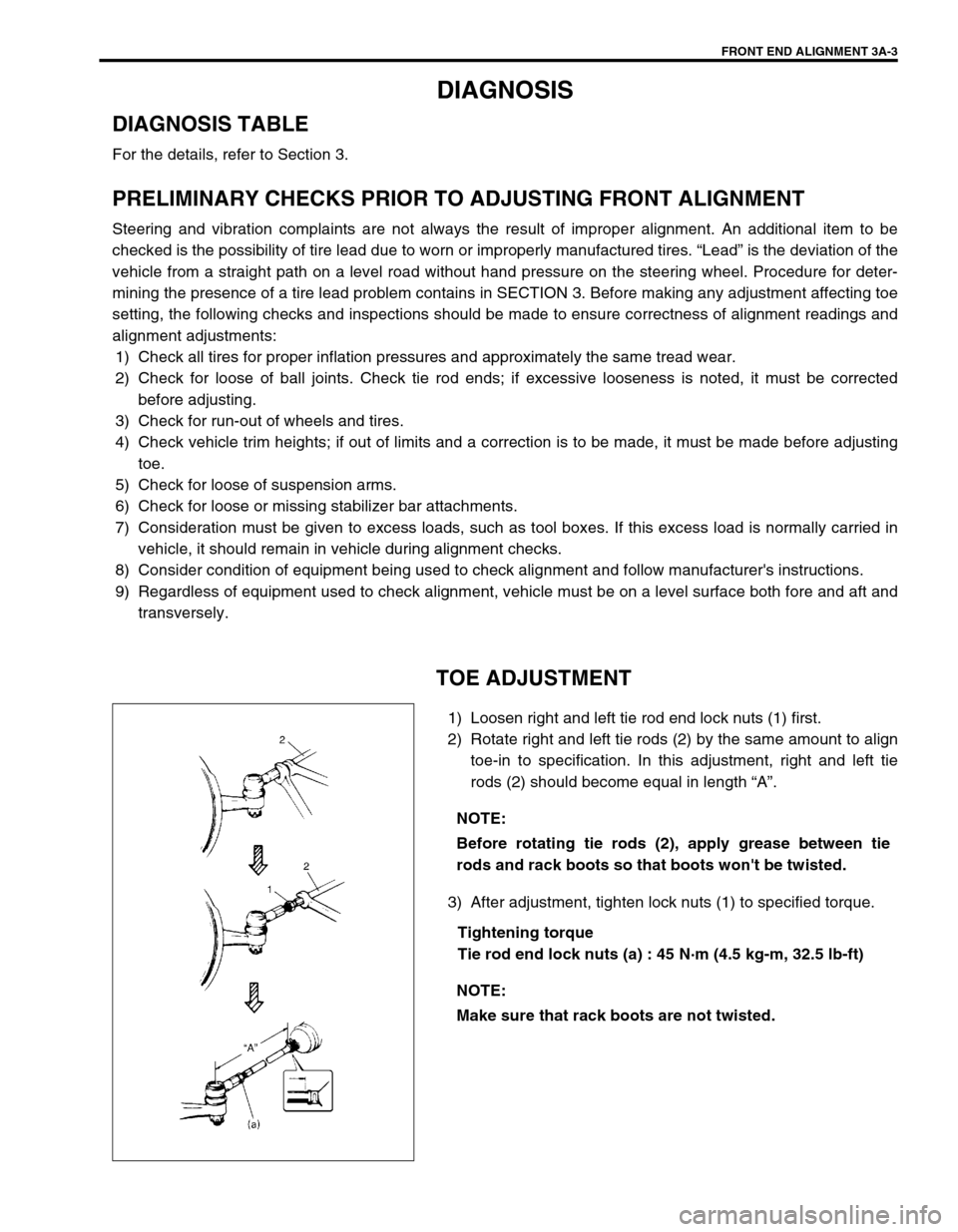
1) Loosen right and left tie rod end lock nuts (1) first.
2) Rotate right and left tie rods (2) by the same amount to align
toe-in to specification. In this adjustment, right and left tie
rods (2) should become equal in length “A”.
3) After adjustment, tighten lock nuts (1) to specified torque.
Tightening torque
Tie rod end lock nuts (a) : 45 N·m (4.5 kg-m, 32.5 lb-ft) NOTE:
Before rotating tie rods (2), apply grease between tie
rods and rack boots so that boots won't be twisted.
NOTE:
Make sure that rack boots are not twisted.
Page 121 of 698
3A-4 FRONT END ALIGNMENT
CAMBER AND CASTER CHECK AND
ADJUSTMENT
Should camber or caster be found out of specifications upon
inspection, locate its cause first.
If it is in damaged, loose, bent, dented or worn suspension parts,
they should be replaced.
If it is in vehicle body, repair it so as to attain specifications.
STEERING ANGLE CHECK AND ADJUST-
MENT
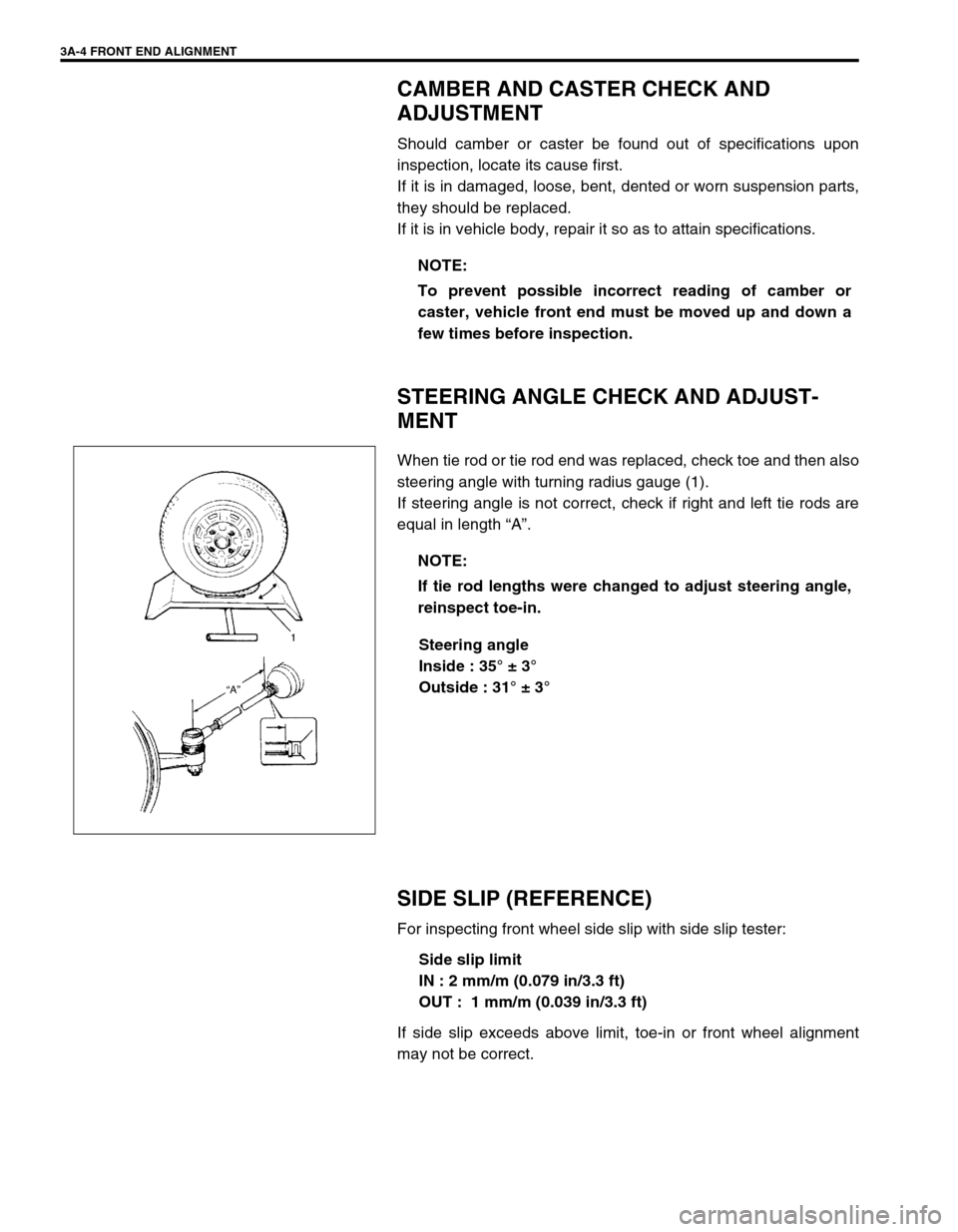
When tie rod or tie rod end was replaced, check toe and then also
steering angle with turning radius gauge (1).
If steering angle is not correct, check if right and left tie rods are
equal in length “A”.
Steering angle
Inside : 35° ± 3°
Outside : 31° ± 3°
SIDE SLIP (REFERENCE)
For inspecting front wheel side slip with side slip tester:
Side slip limit
IN : 2 mm/m (0.079 in/3.3 ft)
OUT : 1 mm/m (0.039 in/3.3 ft)
If side slip exceeds above limit, toe-in or front wheel alignment
may not be correct.NOTE:
To prevent possible incorrect reading of camber or
caster, vehicle front end must be moved up and down a
few times before inspection.
NOTE:
If tie rod lengths were changed to adjust steering angle,
reinspect toe-in.
Page 123 of 698
3B-2 MANUAL RACK AND PINION
GENERAL DESCRIPTION
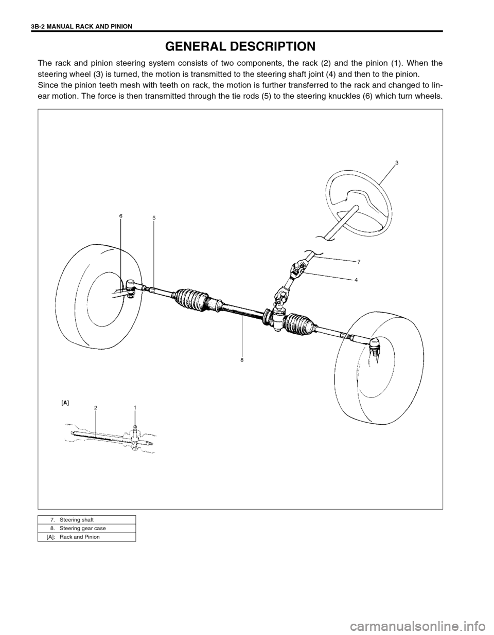
The rack and pinion steering system consists of two components, the rack (2) and the pinion (1). When the
steering wheel (3) is turned, the motion is transmitted to the steering shaft joint (4) and then to the pinion.
Since the pinion teeth mesh with teeth on rack, the motion is further transferred to the rack and changed to lin-
ear motion. The force is then transmitted through the tie rods (5) to the steering knuckles (6) which turn wheels.
7. Steering shaft
8. Steering gear case
[A]: Rack and Pinion
Page 125 of 698
3B-4 MANUAL RACK AND PINION
STEERING WHEEL CHECK
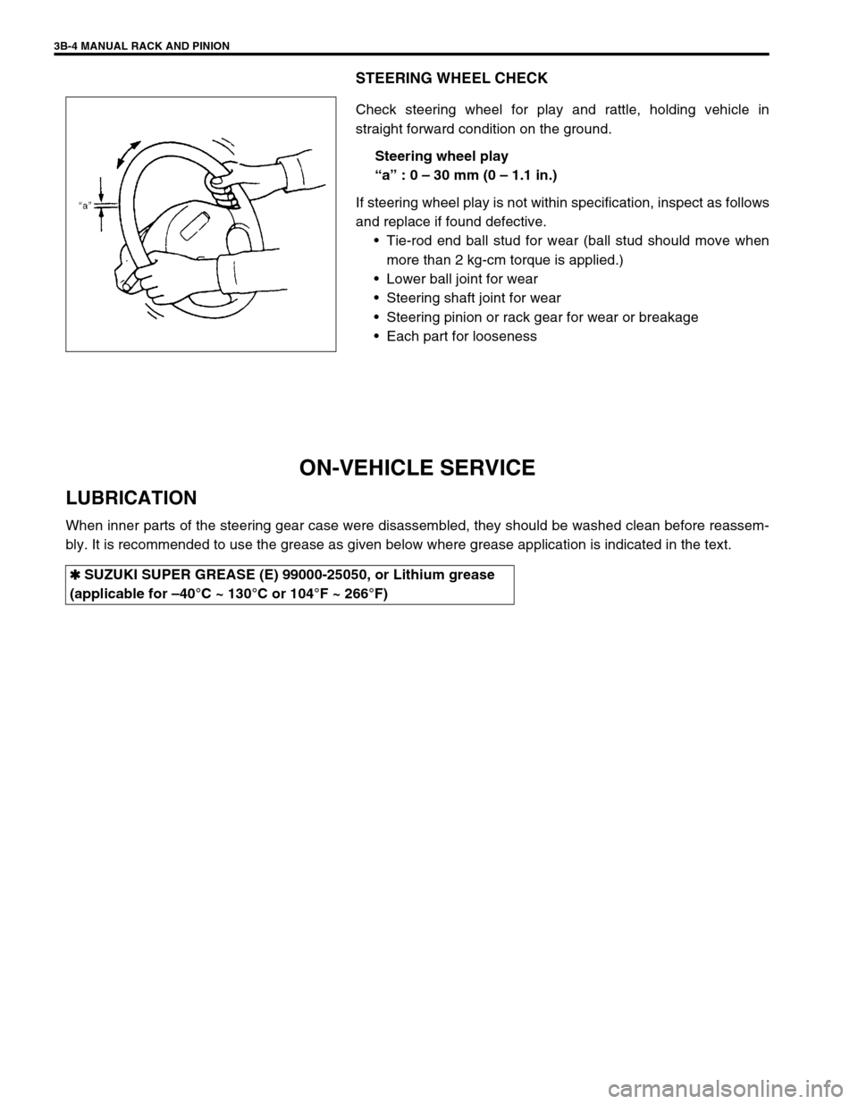
Check steering wheel for play and rattle, holding vehicle in
straight forward condition on the ground.
Steering wheel play
“a” : 0 – 30 mm (0 – 1.1 in.)
If steering wheel play is not within specification, inspect as follows
and replace if found defective.
Tie-rod end ball stud for wear (ball stud should move when
more than 2 kg-cm torque is applied.)
Lower ball joint for wear
Steering shaft joint for wear
Steering pinion or rack gear for wear or breakage
Each part for looseness
ON-VEHICLE SERVICE
LUBRICATION
When inner parts of the steering gear case were disassembled, they should be washed clean before reassem-
bly. It is recommended to use the grease as given below where grease application is indicated in the text.
✱
✱✱ ✱ SUZUKI SUPER GREASE (E) 99000-25050, or Lithium grease
(applicable for –40°C ~ 130°C or 104°F ~ 266°F)
Page 127 of 698
3B-6 MANUAL RACK AND PINION
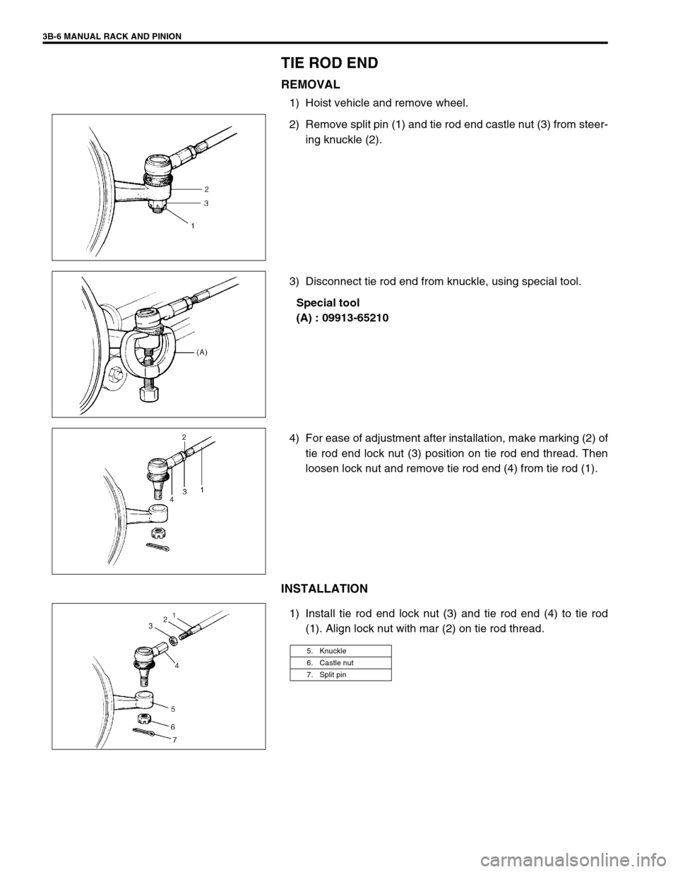
TIE ROD END
REMOVAL
1) Hoist vehicle and remove wheel.
2) Remove split pin (1) and tie rod end castle nut (3) from steer-
ing knuckle (2).
3) Disconnect tie rod end from knuckle, using special tool.
Special tool
(A) : 09913-65210
4) For ease of adjustment after installation, make marking (2) of
tie rod end lock nut (3) position on tie rod end thread. Then
loosen lock nut and remove tie rod end (4) from tie rod (1).
INSTALLATION
1) Install tie rod end lock nut (3) and tie rod end (4) to tie rod
(1). Align lock nut with mar (2) on tie rod thread.
5. Knuckle
6. Castle nut
7. Split pin