wiring diagram SUZUKI SWIFT 2000 1.G RG413 Service Owner's Manual
[x] Cancel search | Manufacturer: SUZUKI, Model Year: 2000, Model line: SWIFT, Model: SUZUKI SWIFT 2000 1.GPages: 698, PDF Size: 16.01 MB
Page 443 of 698
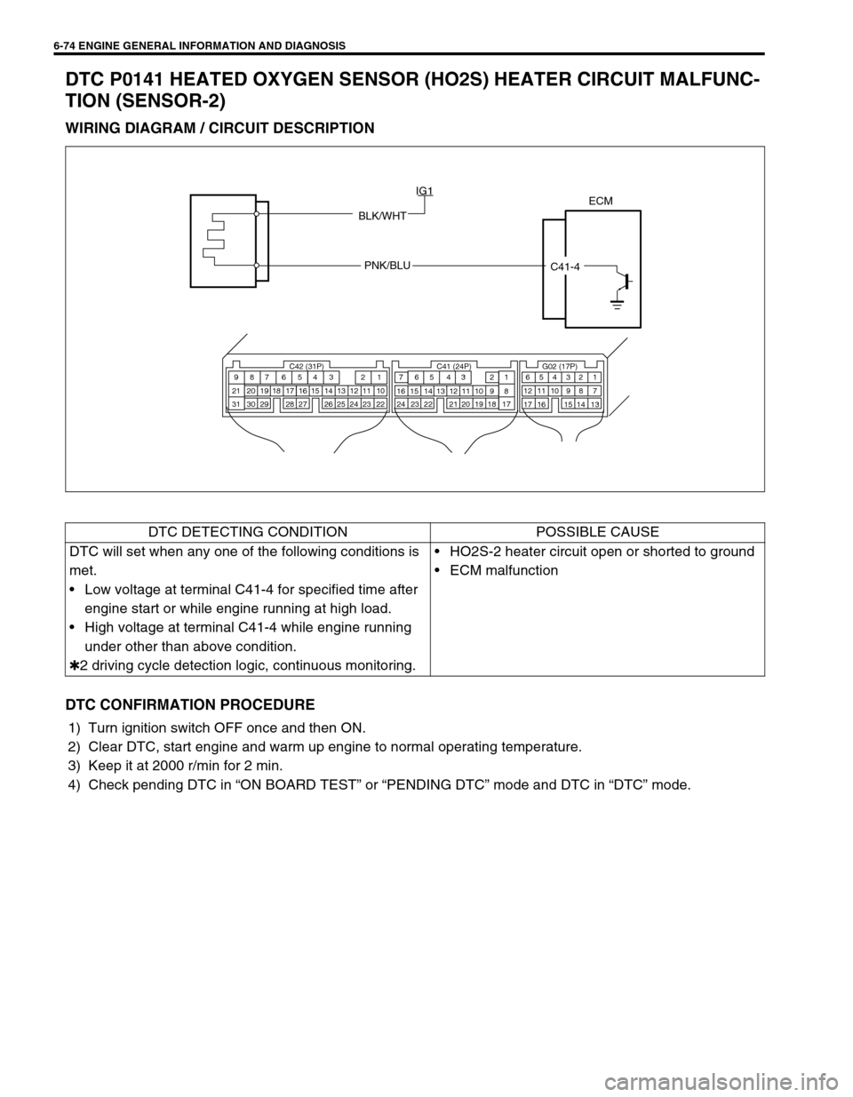
6-74 ENGINE GENERAL INFORMATION AND DIAGNOSIS
DTC P0141 HEATED OXYGEN SENSOR (HO2S) HEATER CIRCUIT MALFUNC-
TION (SENSOR-2)
WIRING DIAGRAM / CIRCUIT DESCRIPTION
DTC CONFIRMATION PROCEDURE
1) Turn ignition switch OFF once and then ON.
2) Clear DTC, start engine and warm up engine to normal operating temperature.
3) Keep it at 2000 r/min for 2 min.
4) Check pending DTC in “ON BOARD TEST” or “PENDING DTC” mode and DTC in “DTC” mode.
ECM
BLK/WHT
PNK/BLU
C41-4 IG1
C42 (31P) C41 (24P) G02 (17P)1 2 3 4 5 6 7 8 9
10 11 12 13 14 15 16 17 18 19 20 21
22 23 24 25 26 28 27 29 30 315 6
1 2 3 4 5 6 7
11 12
9 10 11 13 12 14 15 16
16 171 2
7 8
13 14 3 4
9 10
15 17 188
19 20 21 22 23 24
DTC DETECTING CONDITION POSSIBLE CAUSE
DTC will set when any one of the following conditions is
met.
Low voltage at terminal C41-4 for specified time after
engine start or while engine running at high load.
High voltage at terminal C41-4 while engine running
under other than above condition.
✱2 driving cycle detection logic, continuous monitoring.HO2S-2 heater circuit open or shorted to ground
ECM malfunction
Page 445 of 698
![SUZUKI SWIFT 2000 1.G RG413 Service Owners Manual 6-76 ENGINE GENERAL INFORMATION AND DIAGNOSIS
DTC P0171 FUEL SYSTEM TOO LEAN
DTC P0172 FUEL SYSTEM TOO RICH
WIRING DIAGRAM / CIRCUIT DESCRIPTION
1. Injector [a] : Signal to decrease amount of fuel inj SUZUKI SWIFT 2000 1.G RG413 Service Owners Manual 6-76 ENGINE GENERAL INFORMATION AND DIAGNOSIS
DTC P0171 FUEL SYSTEM TOO LEAN
DTC P0172 FUEL SYSTEM TOO RICH
WIRING DIAGRAM / CIRCUIT DESCRIPTION
1. Injector [a] : Signal to decrease amount of fuel inj](/img/20/7606/w960_7606-444.png)
6-76 ENGINE GENERAL INFORMATION AND DIAGNOSIS
DTC P0171 FUEL SYSTEM TOO LEAN
DTC P0172 FUEL SYSTEM TOO RICH
WIRING DIAGRAM / CIRCUIT DESCRIPTION
1. Injector [a] : Signal to decrease amount of fuel injection [f] : A/F mixture becomes leaner
2. HO2S-1 [b] : Signal to increase amount of fuel injection [g] : Oxygen concentration decreases
3. WU-TWC (Warm up-three way catalytic convec-
tor)[c] : High voltage [h] : Oxygen concentration increases
4. Sensed information [d] : Low voltage
5. ECM [e] : A/F mixture becomes richer
[a]
[b]
[f] [e] [g][d]
[h][c]
1
2 5
1
2
2
3
54
+BECM
C42-9
C42-21
C42-8 C42-31
C42-1
BLU/YEL
BLU/WHT
BLU/RED
BLK/ORN
C42-3
BLK/ORN BLU/ORN
WHT
ORNC42-10C42-13
E111
DTC DETECTING CONDITION POSSIBLE CAUSE
When one of the following conditions occurs while
engine running under closed loop condition.
Air/fuel ratio too lean
(Total fuel trim (short and long terms added) is more
than 30%)
Air/fuel ratio too rich
(Total fuel trim is less than – 30%)
✱2 driving cycle detection logic, continuous monitoring.Vacuum leaks (air drawn in).
Exhaust gas leakage.
Heated oxygen sensor-1 circuit malfunction.
Fuel pressure out of specification.
Fuel injector malfunction (clogged or leakage).
MAP sensor poor performance.
ECT sensor poor performance.
IAT sensor poor performance.
TP sensor poor performance.
EVAP control system malfunction.
PCV valve malfunction.
Page 450 of 698
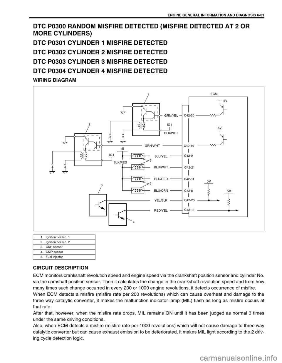
ENGINE GENERAL INFORMATION AND DIAGNOSIS 6-81
DTC P0300 RANDOM MISFIRE DETECTED (MISFIRE DETECTED AT 2 OR
MORE CYLINDERS)
DTC P0301 CYLINDER 1 MISFIRE DETECTED
DTC P0302 CYLINDER 2 MISFIRE DETECTED
DTC P0303 CYLINDER 3 MISFIRE DETECTED
DTC P0304 CYLINDER 4 MISFIRE DETECTED
WIRING DIAGRAM
CIRCUIT DESCRIPTION
ECM monitors crankshaft revolution speed and engine speed via the crankshaft position sensor and cylinder No.
via the camshaft position sensor. Then it calculates the change in the crankshaft revolution speed and from how
many times such change occurred in every 200 or 1000 engine revolutions, it detects occurrence of misfire.
When ECM detects a misfire (misfire rate per 200 revolutions) which can cause overheat and damage to the
three way catalytic converter, it makes the malfunction indicator lamp (MIL) flash as long as misfire occurs at
that rate.
After that, however, when the misfire rate drops, MIL remains ON until it has been judged as normal 3 times
under the same driving conditions.
Also, when ECM detects a misfire (misfire rate per 1000 revolutions) which will not cause damage to three way
catalytic converter but can cause exhaust emission to be deteriorated, it makes MIL light according to the 2 driv-
ing cycle detection logic.
1. Ignition coil No. 1
2. Ignition coil No. 2
3. CKP sensor
4. CMP sensor
5. Fuel injector
C42-20
C42-19
ECM
IG1
5V
5V
GRN/YEL
BLK/WHT
GRN/WHT
IG1 2
+B
C42-9
C42-21
C42-8
C42-23 C42-31 BLU/YEL
BLU/WHT
BLU/RED
BLU/ORN
YEL/BLK
5V
C42-11
RED/YEL
5V
BLK/RED
3
45
5
1
Page 455 of 698
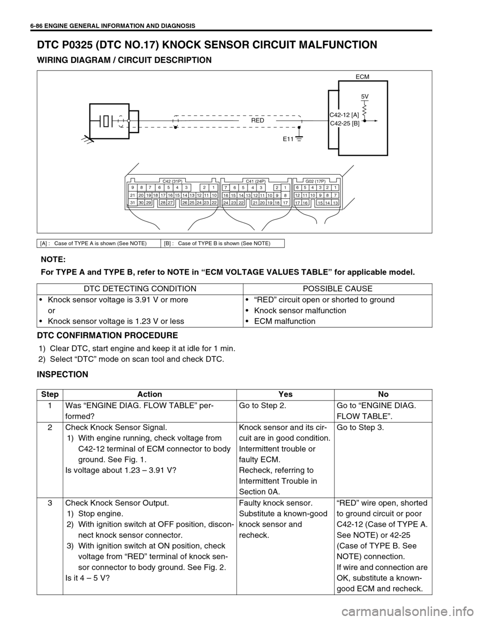
6-86 ENGINE GENERAL INFORMATION AND DIAGNOSIS
DTC P0325 (DTC NO.17) KNOCK SENSOR CIRCUIT MALFUNCTION
WIRING DIAGRAM / CIRCUIT DESCRIPTION
DTC CONFIRMATION PROCEDURE
1) Clear DTC, start engine and keep it at idle for 1 min.
2) Select “DTC” mode on scan tool and check DTC.
INSPECTION
[A] : Case of TYPE A is shown (See NOTE) [B] : Case of TYPE B is shown (See NOTE)
ECM
5V
RED
E11
C42 (31P) C41 (24P) G02 (17P)1 2 3 4 5 6 7 8 9
10 11 12 13 14 15 16 17 18 19 20 21
22 23 24 25 26 28 27 29 30 315 6
1 2 3 4 5 6 7
11 12
9 10 11 13 12 14 15 16
16 171 2
7 8
13 14 3 4
9 10
15 17 188
19 20 21 22 23 24
C42-12 [A]
C42-25 [B]
NOTE:
For TYPE A and TYPE B, refer to NOTE in “ECM VOLTAGE VALUES TABLE” for applicable model.
DTC DETECTING CONDITION POSSIBLE CAUSE
Knock sensor voltage is 3.91 V or more
or
Knock sensor voltage is 1.23 V or less“RED” circuit open or shorted to ground
Knock sensor malfunction
ECM malfunction
Step Action Yes No
1Was “ENGINE DIAG. FLOW TABLE” per-
formed?Go to Step 2. Go to “ENGINE DIAG.
FLOW TABLE”.
2 Check Knock Sensor Signal.
1) With engine running, check voltage from
C42-12 terminal of ECM connector to body
ground. See Fig. 1.
Is voltage about 1.23 – 3.91 V?Knock sensor and its cir-
cuit are in good condition.
Intermittent trouble or
faulty ECM.
Recheck, referring to
Intermittent Trouble in
Section 0A.Go to Step 3.
3 Check Knock Sensor Output.
1) Stop engine.
2) With ignition switch at OFF position, discon-
nect knock sensor connector.
3) With ignition switch at ON position, check
voltage from “RED” terminal of knock sen-
sor connector to body ground. See Fig. 2.
Is it 4 – 5 V?Faulty knock sensor.
Substitute a known-good
knock sensor and
recheck.“RED” wire open, shorted
to ground circuit or poor
C42-12 (Case of TYPE A.
See NOTE) or 42-25
(Case of TYPE B. See
NOTE) connection.
If wire and connection are
OK, substitute a known-
good ECM and recheck.
Page 457 of 698
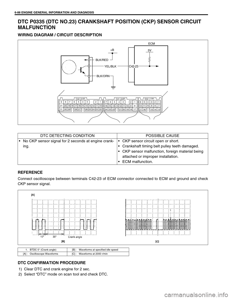
6-88 ENGINE GENERAL INFORMATION AND DIAGNOSIS
DTC P0335 (DTC NO.23) CRANKSHAFT POSITION (CKP) SENSOR CIRCUIT
MALFUNCTION
WIRING DIAGRAM / CIRCUIT DESCRIPTION
REFERENCE
Connect oscilloscope between terminals C42-23 of ECM connector connected to ECM and ground and check
CKP sensor signal.
DTC CONFIRMATION PROCEDURE
1) Clear DTC and crank engine for 2 sec.
2) Select “DTC” mode on scan tool and check DTC.
ECM
5V+B
BLK/RED
YEL/BLK
C42-23
BLK/ORN
C42 (31P) C41 (24P) G02 (17P)1 2 3 4 5 6 7 8 9
10 11 12 13 14 15 16 17 18 19 20 21
22 23 24 25 26 28 27 29 30 315 6
1 2 3 4 5 6 7
11 12
9 10 11 13 12 14 15 16
16 171 2
7 8
13 14 3 4
9 10
15 17 188
19 20 21 22 23 24
DTC DETECTING CONDITION POSSIBLE CAUSE
No CKP sensor signal for 2 seconds at engine crank-
ing.CKP sensor circuit open or short.
Crankshaft timing belt pulley teeth damaged.
CKP sensor malfunction, foreign material being
attached or improper installation.
ECM malfunction.
1. BTDC 5° (Crank angle) [B] : Waveforms at specified idle speed
[A] : Oscilloscope Waveforms [C] : Waveforms at 2000 r/min
Page 460 of 698
ENGINE GENERAL INFORMATION AND DIAGNOSIS 6-91
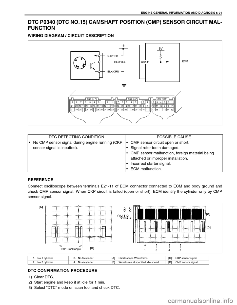
DTC P0340 (DTC NO.15) CAMSHAFT POSITION (CMP) SENSOR CIRCUIT MAL-
FUNCTION
WIRING DIAGRAM / CIRCUIT DESCRIPTION
REFERENCE
Connect oscilloscope between terminals E21-11 of ECM connector connected to ECM and body ground and
check CMP sensor signal. When CKP circuit is failed (open or short), ECM identify the cylinder only by CMP
sensor signal.
DTC CONFIRMATION PROCEDURE
1) Clear DTC.
2) Start engine and keep it at idle for 1 min.
3) Select “DTC” mode on scan tool and check DTC.
ECM
5V+B
BLK/RED
RED/YEL
BLK/ORN
C42 (31P) C41 (24P) G02 (17P)1 2 3 4 5 6 7 8 9
10 11 12 13 14 15 16 17 18 19 20 21
22 23 24 25 26 28 27 29 30 315 6
1 2 3 4 5 6 7
11 12
9 10 11 13 12 14 15 16
16 171 2
7 8
13 14 3 4
9 10
15 17 188
19 20 21 22 23 24
C42-11
DTC DETECTING CONDITION POSSIBLE CAUSE
No CMP sensor signal during engine running (CKP
sensor signal is inputted).CMP sensor circuit open or short.
Signal rotor teeth damaged.
CMP sensor malfunction, foreign material being
attached or improper installation.
Incorrect starter signal.
ECM malfunction.
1. No.1 cylinder 3. No.3 cylinder [A] : Oscilloscope Waveforms [C] : CKP sensor signal
2. No.2 cylinder 4. No.4 cylinder [B] : Waveforms at specified idle speed [D] : CMP sensor signal
Page 463 of 698
6-94 ENGINE GENERAL INFORMATION AND DIAGNOSIS
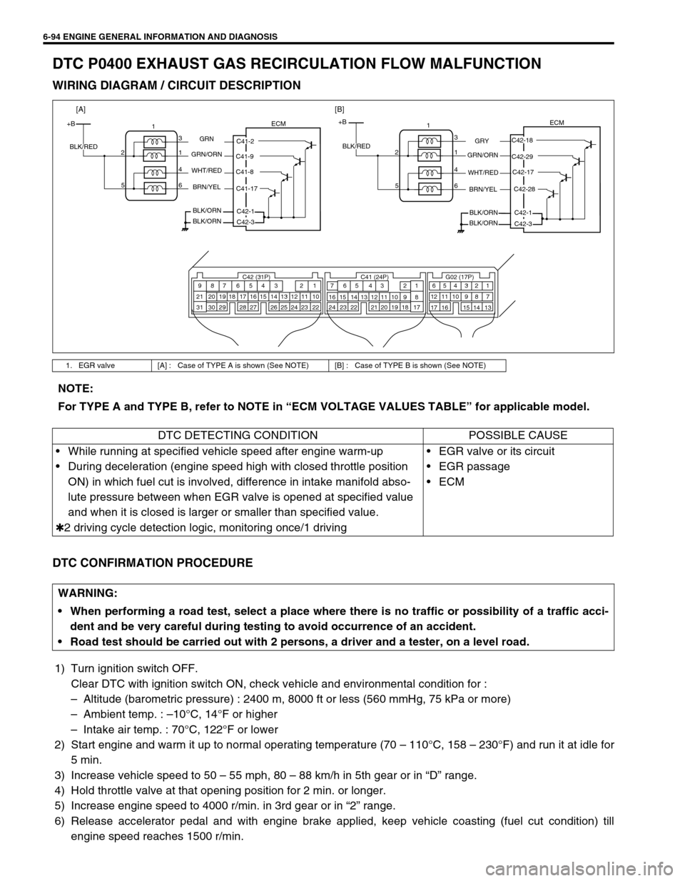
DTC P0400 EXHAUST GAS RECIRCULATION FLOW MALFUNCTION
WIRING DIAGRAM / CIRCUIT DESCRIPTION
DTC CONFIRMATION PROCEDURE
1) Turn ignition switch OFF.
Clear DTC with ignition switch ON, check vehicle and environmental condition for :
–Altitude (barometric pressure) : 2400 m, 8000 ft or less (560 mmHg, 75 kPa or more)
–Ambient temp. : –10°C, 14°F or higher
–Intake air temp. : 70°C, 122°F or lower
2) Start engine and warm it up to normal operating temperature (70 – 110°C, 158 – 230°F) and run it at idle for
5 min.
3) Increase vehicle speed to 50 – 55 mph, 80 – 88 km/h in 5th gear or in “D” range.
4) Hold throttle valve at that opening position for 2 min. or longer.
5) Increase engine speed to 4000 r/min. in 3rd gear or in “2” range.
6) Release accelerator pedal and with engine brake applied, keep vehicle coasting (fuel cut condition) till
engine speed reaches 1500 r/min.
1. EGR valve [A] : Case of TYPE A is shown (See NOTE) [B] : Case of TYPE B is shown (See NOTE)
C42 (31P) C41 (24P) G02 (17P)1 2 3 4 5 6 7 8 9
10 11 12 13 14 15 16 17 18 19 20 21
22 23 24 25 26 28 27 29 30 315 6
1 2 3 4 5 6 7
11 12
9 10 11 13 12 14 15 16
16 171 2
7 8
13 14 3 4
9 10
15 17 188
19 20 21 22 23 24
+BECM
C42-18
C42-29
C42-28 C42-17
C42-1
GRY
GRN/ORN
WHT/RED
C42-3 BRN/YEL
BLK/ORN
BLK/ORN BLK/RED1
3
1 2
4
6 5
+BECM
C41-2
C41-9
C41-17 C41-8
C42-1
GRN
GRN/ORN
WHT/RED
C42-3 BRN/YEL
BLK/ORN
BLK/ORN BLK/RED1
3
1 2
4
6 5
[A][B]
NOTE:
For TYPE A and TYPE B, refer to NOTE in “ECM VOLTAGE VALUES TABLE” for applicable model.
DTC DETECTING CONDITION POSSIBLE CAUSE
While running at specified vehicle speed after engine warm-up
During deceleration (engine speed high with closed throttle position
ON) in which fuel cut is involved, difference in intake manifold abso-
lute pressure between when EGR valve is opened at specified value
and when it is closed is larger or smaller than specified value.
✱2 driving cycle detection logic, monitoring once/1 drivingEGR valve or its circuit
EGR passage
ECM
WARNING:
When performing a road test, select a place where there is no traffic or possibility of a traffic acci-
dent and be very careful during testing to avoid occurrence of an accident.
Road test should be carried out with 2 persons, a driver and a tester, on a level road.
Page 466 of 698
ENGINE GENERAL INFORMATION AND DIAGNOSIS 6-97
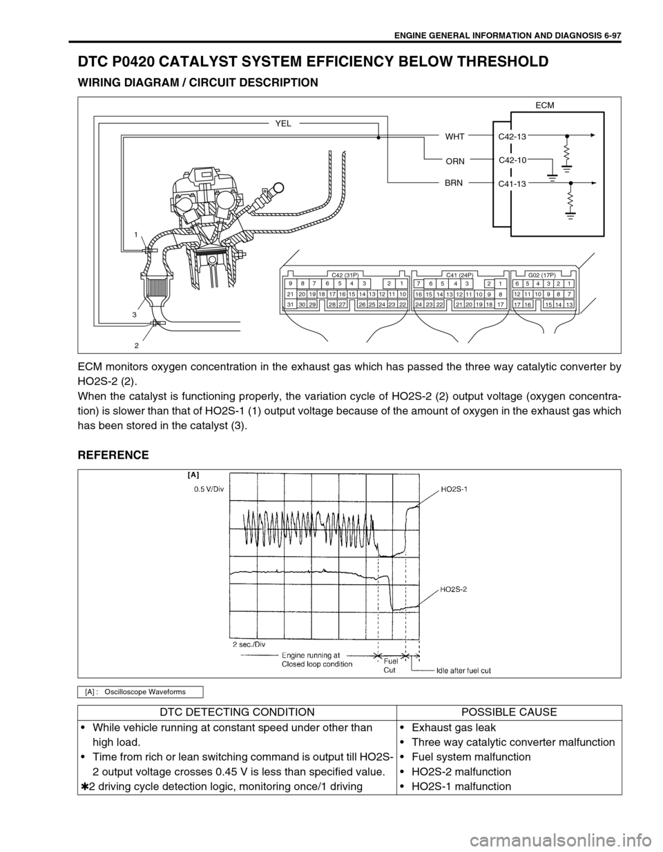
DTC P0420 CATALYST SYSTEM EFFICIENCY BELOW THRESHOLD
WIRING DIAGRAM / CIRCUIT DESCRIPTION
ECM monitors oxygen concentration in the exhaust gas which has passed the three way catalytic converter by
HO2S-2 (2).
When the catalyst is functioning properly, the variation cycle of HO2S-2 (2) output voltage (oxygen concentra-
tion) is slower than that of HO2S-1 (1) output voltage because of the amount of oxygen in the exhaust gas which
has been stored in the catalyst (3).
REFERENCE
[A] : Oscilloscope Waveforms
C42 (31P) C41 (24P) G02 (17P)1 2 3 4 5 6 7 8 9
10 11 12 13 14 15 16 17 18 19 20 21
22 23 24 25 26 28 27 29 30 315 6
1 2 3 4 5 6 7
11 12
9 10 11 13 12 14 15 16
16 171 2
7 8
13 14 3 4
9 10
15 17 188
19 20 21 22 23 24
1
2
3
ECM
WHT
ORNC42-10 C42-13
BRN
C41-13
YEL
DTC DETECTING CONDITION POSSIBLE CAUSE
While vehicle running at constant speed under other than
high load.
Time from rich or lean switching command is output till HO2S-
2 output voltage crosses 0.45 V is less than specified value.
✱2 driving cycle detection logic, monitoring once/1 drivingExhaust gas leak
Three way catalytic converter malfunction
Fuel system malfunction
HO2S-2 malfunction
HO2S-1 malfunction
Page 469 of 698
6-100 ENGINE GENERAL INFORMATION AND DIAGNOSIS
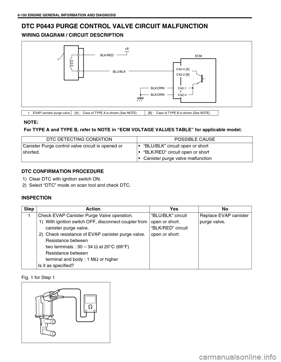
DTC P0443 PURGE CONTROL VALVE CIRCUIT MALFUNCTION
WIRING DIAGRAM / CIRCUIT DESCRIPTION
DTC CONFIRMATION PROCEDURE
1) Clear DTC with ignition switch ON.
2) Select “DTC” mode on scan tool and check DTC.
INSPECTION
Fig. 1 for Step 1
1. EVAP canister purge valve [A] : Case of TYPE A is shown (See NOTE) [B] : Case of TYPE B is shown (See NOTE)
ECM
+B
BLK/RED
BLU/BLK
BLK/ORN
BLK/ORNC42-1
C42-3
1
C42-4 [A]
C42-2 [B]
NOTE:
For TYPE A and TYPE B, refer to NOTE in “ECM VOLTAGE VALUES TABLE” for applicable model.
DTC DETECTING CONDITION POSSIBLE CAUSE
Canister Purge control valve circuit is opened or
shorted.“BLU/BLK” circuit open or short
“BLK/RED” circuit open or short
Canister purge valve malfunction
Step Action Yes No
1 Check EVAP Canister Purge Valve operation.
1) With ignition switch OFF, disconnect coupler from
canister purge valve.
2) Check resistance of EVAP canister purge valve.
Resistance between
two terminals : 30 – 34 Ω at 20°C (68°F)
Resistance between
terminal and body : 1 MΩ or higher
Is it as specified?“BLU/BLK” circuit
open or short.
“BLK/RED” circuit
open or short.Replace EVAP canister
purge valve.
Page 470 of 698
ENGINE GENERAL INFORMATION AND DIAGNOSIS 6-101
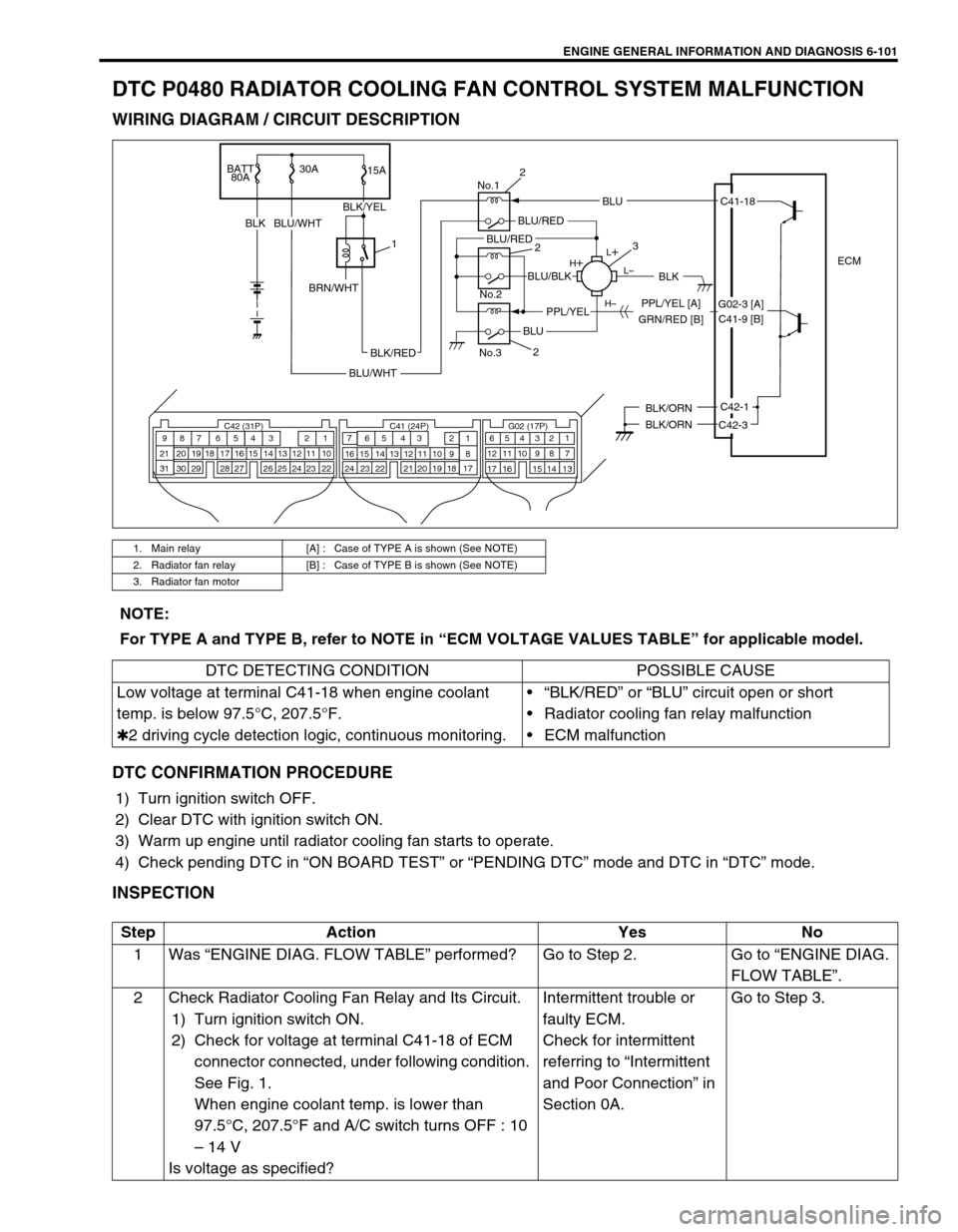
DTC P0480 RADIATOR COOLING FAN CONTROL SYSTEM MALFUNCTION
WIRING DIAGRAM / CIRCUIT DESCRIPTION
DTC CONFIRMATION PROCEDURE
1) Turn ignition switch OFF.
2) Clear DTC with ignition switch ON.
3) Warm up engine until radiator cooling fan starts to operate.
4) Check pending DTC in “ON BOARD TEST” or “PENDING DTC” mode and DTC in “DTC” mode.
INSPECTION
1. Main relay [A] : Case of TYPE A is shown (See NOTE)
2. Radiator fan relay [B] : Case of TYPE B is shown (See NOTE)
3. Radiator fan motor
BATT
80A30A
15A
BLKBLU/WHT
ECM
BLK/ORN
BLK/ORNC42-1
C42-3
L
L–
H– H
No.1
No.2
No.3
BLU
C42 (31P) C41 (24P) G02 (17P)1 2 3 4 5 6 7 8 9
10 11 12 13 14 15 16 17 18 19 20 21
22 23 24 25 26 28 27 29 30 315 6
1 2 3 4 5 6 7
11 12
9 10 11 13 12 14 15 16
16 171 2
7 8
13 14 3 4
9 10
15 17 188
19 20 21 22 23 24
C41-18
GRN/RED [B]PPL/YEL [A]
BLK/RED
BLU/WHT
BLU/RED
BLK
BLU
BLU/BLK
PPL/YEL
BLU/RED
BLK/YEL
1
BRN/WHT
2
3
2
2
G02-3 [A]
C41-9 [B]
NOTE:
For TYPE A and TYPE B, refer to NOTE in “ECM VOLTAGE VALUES TABLE” for applicable model.
DTC DETECTING CONDITION POSSIBLE CAUSE
Low voltage at terminal C41-18 when engine coolant
temp. is below 97.5°C, 207.5°F.
✱2 driving cycle detection logic, continuous monitoring.“BLK/RED” or “BLU” circuit open or short
Radiator cooling fan relay malfunction
ECM malfunction
Step Action Yes No
1Was “ENGINE DIAG. FLOW TABLE” performed? Go to Step 2. Go to “ENGINE DIAG.
FLOW TABLE”.
2 Check Radiator Cooling Fan Relay and Its Circuit.
1) Turn ignition switch ON.
2) Check for voltage at terminal C41-18 of ECM
connector connected, under following condition.
See Fig. 1.
When engine coolant temp. is lower than
97.5°C, 207.5°F and A/C switch turns OFF : 10
– 14 V
Is voltage as specified?Intermittent trouble or
faulty ECM.
Check for intermittent
referring to “Intermittent
and Poor Connection” in
Section 0A.Go to Step 3.