Electric power SUZUKI SWIFT 2000 1.G RG413 Service Owner's Guide
[x] Cancel search | Manufacturer: SUZUKI, Model Year: 2000, Model line: SWIFT, Model: SUZUKI SWIFT 2000 1.GPages: 698, PDF Size: 16.01 MB
Page 167 of 698
3B1-26 ELECTRICAL POWER STEERING (P/S) SYSTEM
INSPECTION OF P/S CONTROL MODULE
AND ITS CIRCUITS
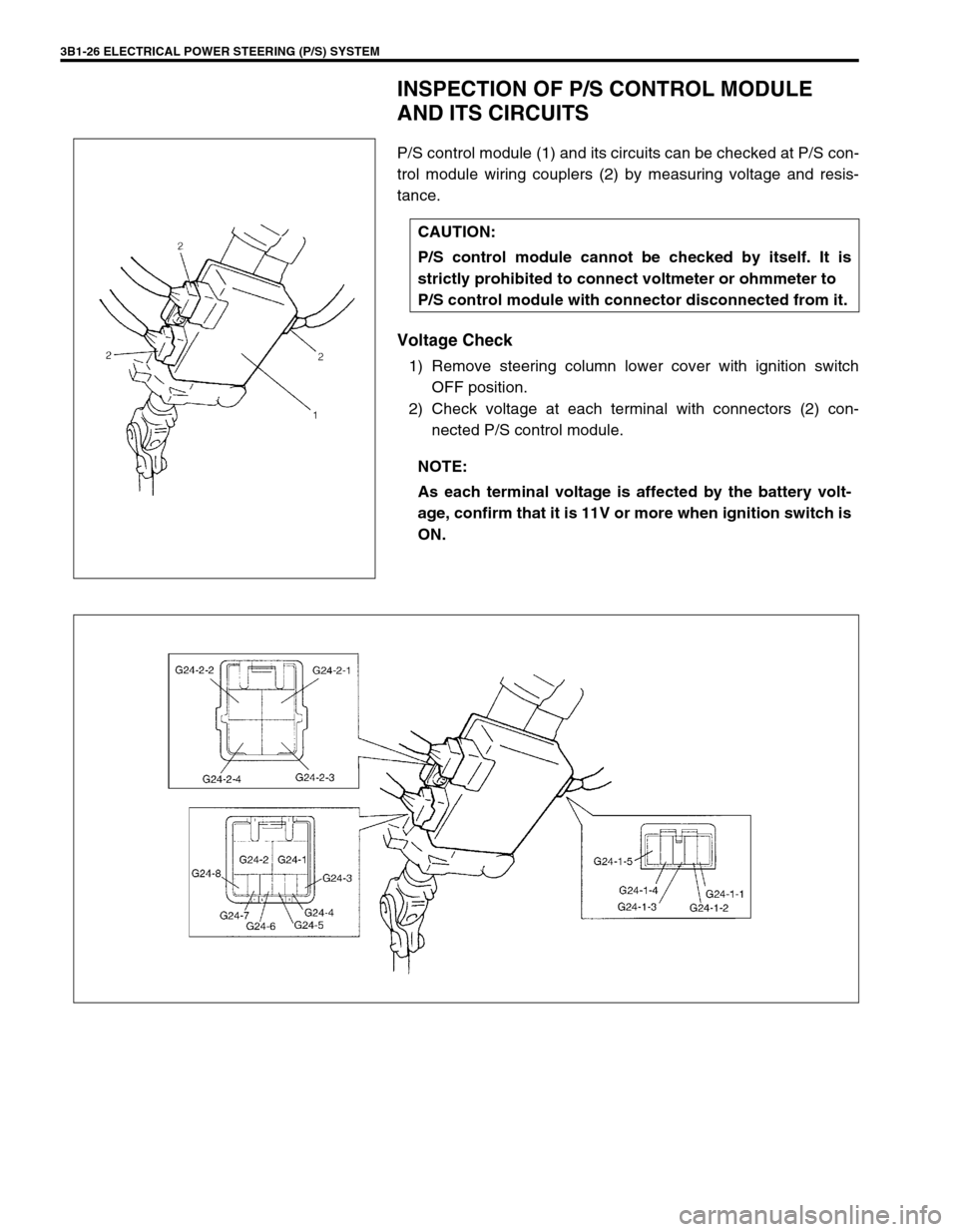
P/S control module (1) and its circuits can be checked at P/S con-
trol module wiring couplers (2) by measuring voltage and resis-
tance.
Voltage Check
1) Remove steering column lower cover with ignition switch
OFF position.
2) Check voltage at each terminal with connectors (2) con-
nected P/S control module. CAUTION:
P/S control module cannot be checked by itself. It is
strictly prohibited to connect voltmeter or ohmmeter to
P/S control module with connector disconnected from it.
NOTE:
As each terminal voltage is affected by the battery volt-
age, confirm that it is 11V or more when ignition switch is
ON.
Page 168 of 698
ELECTRICAL POWER STEERING (P/S) SYSTEM 3B1-27
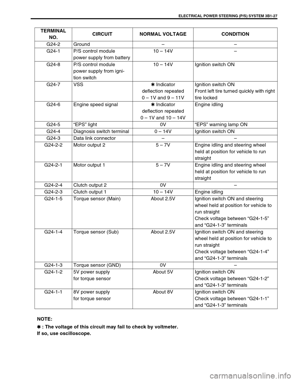
TERMINAL
NO.CIRCUIT NORMAL VOLTAGE CONDITION
G24-2 Ground––
G24-1 P/S control module
power supply from battery10 – 14V–
G24-8 P/S control module
power supply from igni-
tion switch10 – 14V Ignition switch ON
G24-7 VSS✱ Indicator
deflection repeated
0 – 1V and 9 – 11VIgnition switch ON
Front left tire turned quickly with right
tire locked
G24-6 Engine speed signal✱ Indicator
deflection repeated
0 – 1V and 10 – 14VEngine idling
G24-5“EPS” light 0V“EPS” warning lamp ON
G24-4 Diagnosis switch terminal 0 – 14V Ignition switch ON
G24-3 Data link connector––
G24-2-2 Motor output 2 5 – 7V Engine idling and steering wheel
held at position for vehicle to run
straight
G24-2-1 Motor output 1 5 – 7V Engine idling and steering wheel
held at position for vehicle to run
straight
G24-2-4 Clutch output 2 0V–
G24-2-3 Clutch output 1 10 – 14V Engine idling
G24-1-5 Torque sensor (Main) About 2.5V Ignition switch ON and steering
wheel held at position for vehicle to
run straight
Check voltage between “G24-1-5”
and “G24-1-3” terminals
G24-1-4 Torque sensor (Sub) About 2.5V Ignition switch ON and steering
wheel held at position for vehicle to
run straight
Check voltage between “G24-1-4”
and “G24-1-3” terminals
G24-1-3 Torque sensor (GND) 0V–
G24-1-2 5V power supply
for torque sensorAbout 5V Ignition switch ON
Check voltage between “G24-1-2”
and “G24-1-3” terminals
G24-1-1 8V power supply
for torque sensorAbout 8V Ignition switch ON
Check voltage between “G24-1-1”
and “G24-1-3” terminals
NOTE:
✱
✱✱ ✱ : The voltage of this circuit may fail to check by voltmeter.
If so, use oscilloscope.
Page 169 of 698
3B1-28 ELECTRICAL POWER STEERING (P/S) SYSTEM
STEERING WHEEL PLAY INSPECTION
Check steering wheel for looseness or rattle by trying to move it in
its shaft direction and lateral direction.
If found defective, repair or replace.
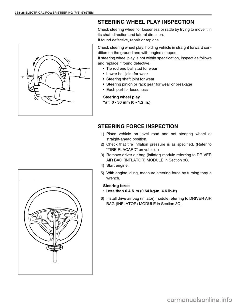
Check steering wheel play, holding vehicle in straight forward con-
dition on the ground and with engine stopped.
If steering wheel play is not within specification, inspect as follows
and replace if found defective.
Tie rod end ball stud for wear
Lower ball joint for wear
Steering shaft joint for wear
Steering pinion or rack gear for wear or breakage
Each part for looseness
Steering wheel play
“a”: 0 - 30 mm (0 - 1.2 in.)
STEERING FORCE INSPECTION
1) Place vehicle on level road and set steering wheel at
straight-ahead position.
2) Check that tire inflation pressure is as specified. (Refer to
“TIRE PLACARD” on vehicle.)
3) Remove driver air bag (inflator) module referring to DRIVER
AIR BAG (INFLATOR) MODULE in Section 3C.
4) Start engine.
5) With engine idling, measure steering force by turning torque
wrench.
Steering force
: Less than 6.4 N·m (0.64 kg·m, 4.6 lb-ft)
6) Install drive air bag (inflator) module referring to DRIVER AIR
BAG (INFLATOR) MODULE in Section 3C.
Page 170 of 698
ELECTRICAL POWER STEERING (P/S) SYSTEM 3B1-29
ON-VEHICLE SERVICE
P/S CONTROL MODULE
REMOVAL
1) Disconnect negative cable at battery.
2) Remove steering column hole cover.
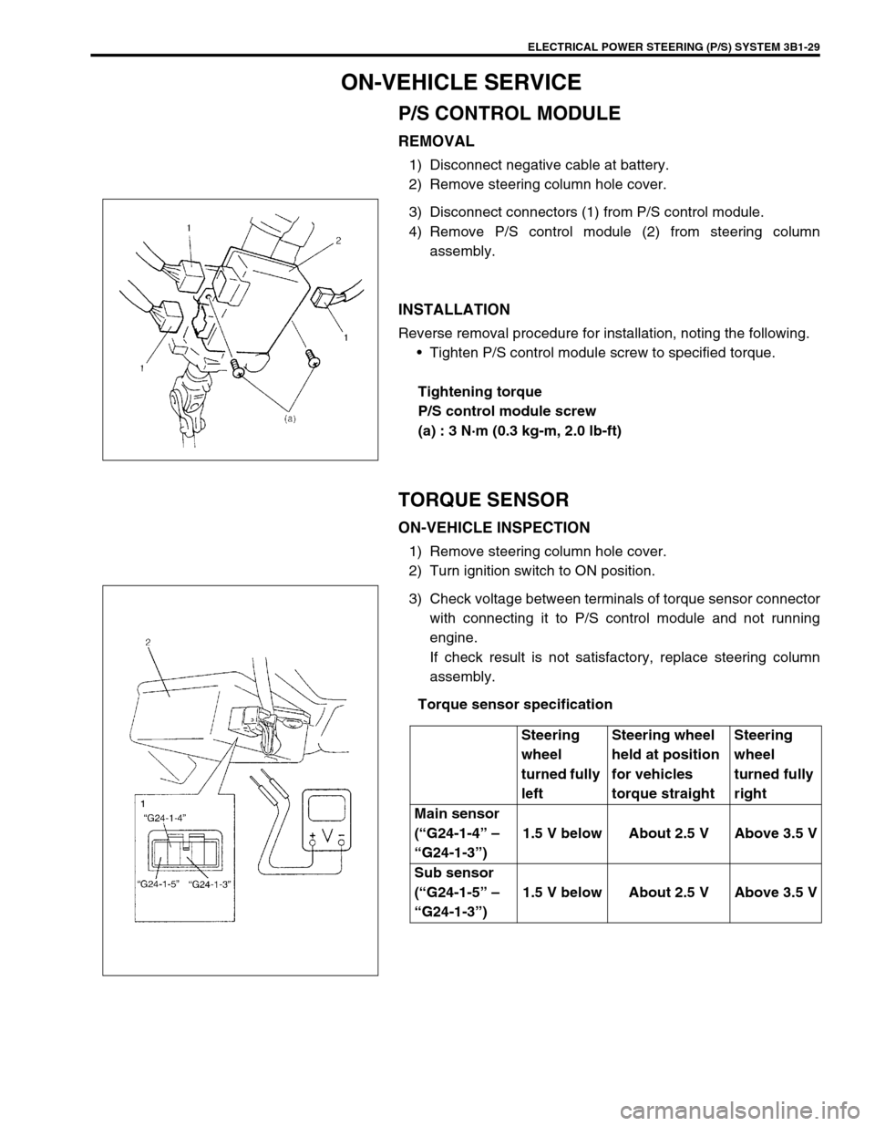
3) Disconnect connectors (1) from P/S control module.
4) Remove P/S control module (2) from steering column
assembly.
INSTALLATION
Reverse removal procedure for installation, noting the following.
Tighten P/S control module screw to specified torque.
Tightening torque
P/S control module screw
(a) : 3 N·m (0.3 kg-m, 2.0 lb-ft)
TORQUE SENSOR
ON-VEHICLE INSPECTION
1) Remove steering column hole cover.
2) Turn ignition switch to ON position.
3) Check voltage between terminals of torque sensor connector
with connecting it to P/S control module and not running
engine.
If check result is not satisfactory, replace steering column
assembly.
Torque sensor specification
Steering
wheel
turned fully
leftSteering wheel
held at position
for vehicles
torque straightSteering
wheel
turned fully
right
Main sensor
(“G24-1-4” –
“G24-1-3”)1.5 V below About 2.5 V Above 3.5 V
Sub sensor
(“G24-1-5” –
“G24-1-3”)1.5 V below About 2.5 V Above 3.5 V
Page 171 of 698
3B1-30 ELECTRICAL POWER STEERING (P/S) SYSTEM
MOTOR AND CLUTCH
ON-VEHICLE INSPECTION
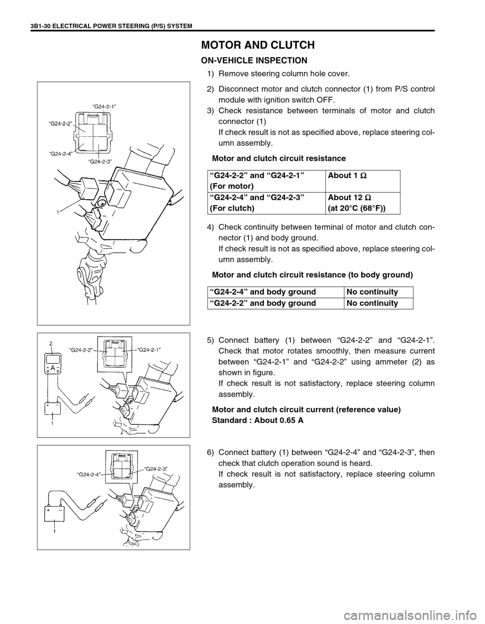
1) Remove steering column hole cover.
2) Disconnect motor and clutch connector (1) from P/S control
module with ignition switch OFF.
3) Check resistance between terminals of motor and clutch
connector (1)
If check result is not as specified above, replace steering col-
umn assembly.
Motor and clutch circuit resistance
4) Check continuity between terminal of motor and clutch con-
nector (1) and body ground.
If check result is not as specified above, replace steering col-
umn assembly.
Motor and clutch circuit resistance (to body ground)
5) Connect battery (1) between “G24-2-2” and “G24-2-1”.
Check that motor rotates smoothly, then measure current
between “G24-2-1” and “G24-2-2” using ammeter (2) as
shown in figure.
If check result is not satisfactory, replace steering column
assembly.
Motor and clutch circuit current (reference value)
Standard : About 0.65 A
6) Connect battery (1) between “G24-2-4” and “G24-2-3”, then
check that clutch operation sound is heard.
If check result is not satisfactory, replace steering column
assembly. “G24-2-2” and “G24-2-1”
(For motor)About 1
Ω
ΩΩ Ω
“G24-2-4” and “G24-2-3”
(For clutch)About 12
Ω
ΩΩ Ω
(at 20°C (68°F))
“G24-2-4” and body ground No continuity
“G24-2-2” and body ground No continuity
Page 172 of 698
ELECTRICAL POWER STEERING (P/S) SYSTEM 3B1-31
STEERING COLUMN ASSEMBLY
Refer to Section 3C for removal and installation of steering col-
umn assembly but perform the following step beforehand.
Disconnect all connectors from P/S control module.
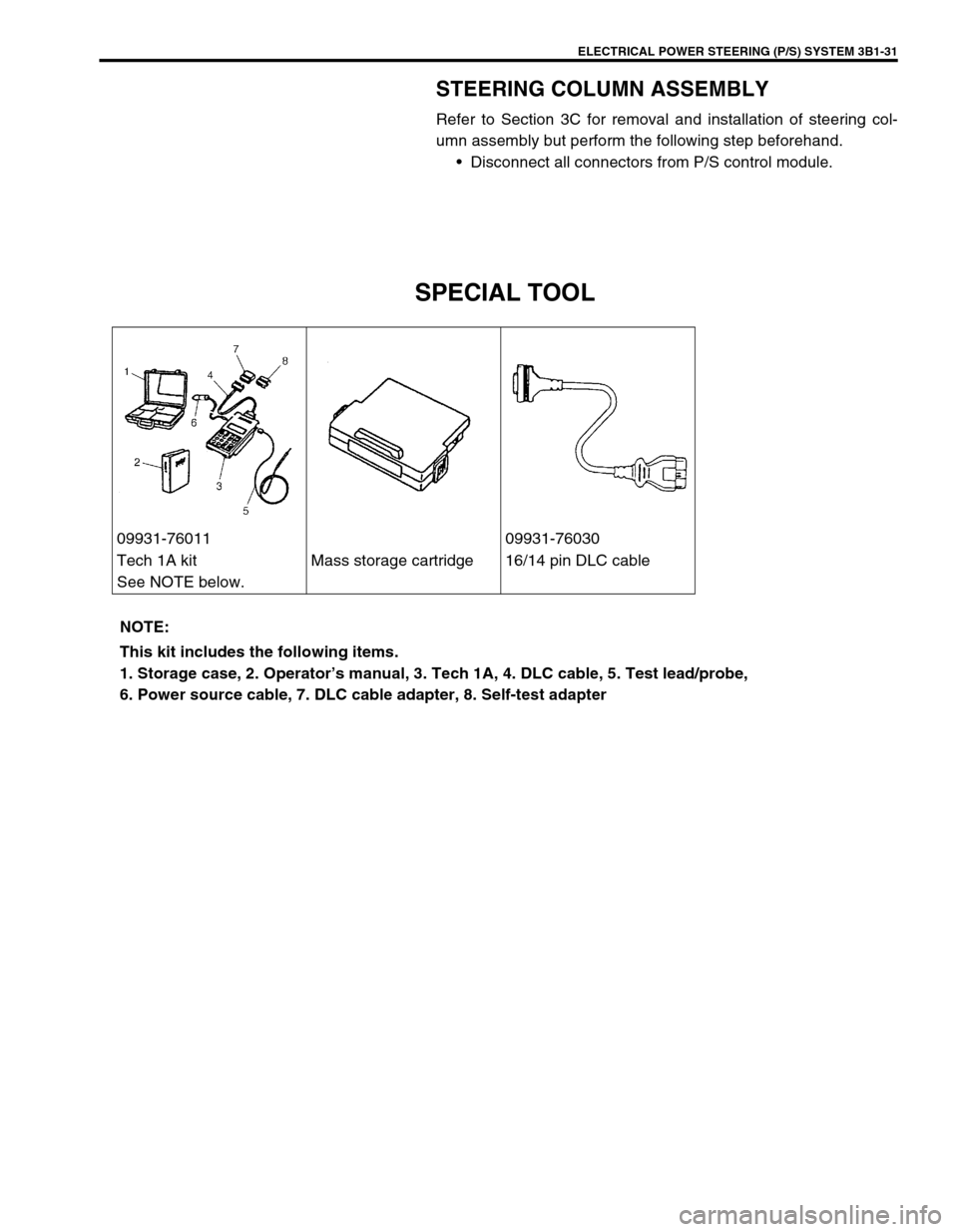
SPECIAL TOOL
09931-76011 09931-76030
Tech 1A kit
See NOTE below.Mass storage cartridge 16/14 pin DLC cable
NOTE:
This kit includes the following items.
1. Storage case, 2. Operator’s manual, 3. Tech 1A, 4. DLC cable, 5. Test lead/probe,
6. Power source cable, 7. DLC cable adapter, 8. Self-test adapter
Page 173 of 698

3B1-32 ELECTRICAL POWER STEERING (P/S) SYSTEM
Page 372 of 698
ENGINE GENERAL INFORMATION AND DIAGNOSIS 6-3
DTC P1500 ENGINE STARTER SIGNAL
CIRCUIT MALFUNCTION ........................... 6-110
DTC P1510 ECM BACK-UP POWER
SUPPLY MALFUNCTION ........................... 6-111
DTC P1600 SERIAL COMMUNICATION
PROBLEM BETWEEN ECM AND TCM...... 6-112
DTC P1717 A/T DRIVE RANGE (PARK/
NEUTRAL POSITION) SIGNAL CIRCUIT
MALFUNCTION .......................................... 6-114
TABLE B-1 FUEL INJECTOR CIRCUIT
CHECK ........................................................ 6-117
TABLE B-2 FUEL PUMP AND ITS CIRCUIT CHECK ....................................................... 6-118
TABLE B-3 FUEL PRESSURE CHECK ..... 6-120
TABLE B-4 IDLE AIR CONTROL
SYSTEM CHECK........................................ 6-122
TABLE B-5 A/C SIGNAL CIRCUITS
CHECK (VEHICLE WITH A/C) ................... 6-124
TABLE B-6 ELECTRIC LOAD SIGNAL
CIRCUIT CHECK ........................................ 6-126
TABLE B-7 RADIATOR FAN CONTROL
SYSTEM CHECK........................................ 6-128
SPECIAL TOOL ............................................. 6-130
Page 380 of 698
ENGINE GENERAL INFORMATION AND DIAGNOSIS 6-11
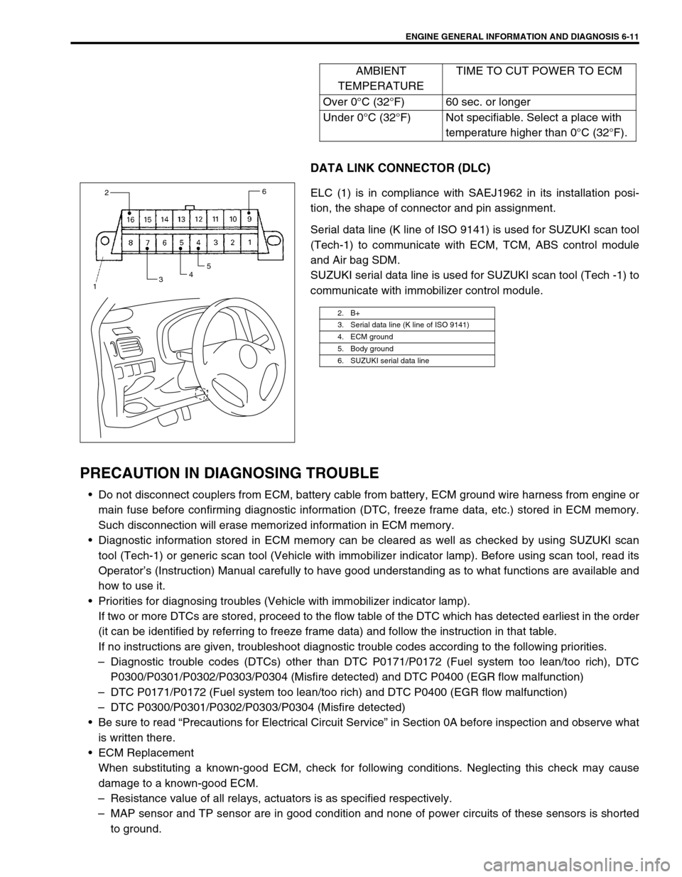
DATA LINK CONNECTOR (DLC)
ELC (1) is in compliance with SAEJ1962 in its installation posi-
tion, the shape of connector and pin assignment.
Serial data line (K line of ISO 9141) is used for SUZUKI scan tool
(Tech-1) to communicate with ECM, TCM, ABS control module
and Air bag SDM.
SUZUKI serial data line is used for SUZUKI scan tool (Tech -1) to
communicate with immobilizer control module.
PRECAUTION IN DIAGNOSING TROUBLE
Do not disconnect couplers from ECM, battery cable from battery, ECM ground wire harness from engine or
main fuse before confirming diagnostic information (DTC, freeze frame data, etc.) stored in ECM memory.
Such disconnection will erase memorized information in ECM memory.
Diagnostic information stored in ECM memory can be cleared as well as checked by using SUZUKI scan
tool (Tech-1) or generic scan tool (Vehicle with immobilizer indicator lamp). Before using scan tool, read its
Operator’s (Instruction) Manual carefully to have good understanding as to what functions are available and
how to use it.
Priorities for diagnosing troubles (Vehicle with immobilizer indicator lamp).
If two or more DTCs are stored, proceed to the flow table of the DTC which has detected earliest in the order
(it can be identified by referring to freeze frame data) and follow the instruction in that table.
If no instructions are given, troubleshoot diagnostic trouble codes according to the following priorities.
–Diagnostic trouble codes (DTCs) other than DTC P0171/P0172 (Fuel system too lean/too rich), DTC
P0300/P0301/P0302/P0303/P0304 (Misfire detected) and DTC P0400 (EGR flow malfunction)
–DTC P0171/P0172 (Fuel system too lean/too rich) and DTC P0400 (EGR flow malfunction)
–DTC P0300/P0301/P0302/P0303/P0304 (Misfire detected)
Be sure to read “Precautions for Electrical Circuit Service” in Section 0A before inspection and observe what
is written there.
ECM Replacement
When substituting a known-good ECM, check for following conditions. Neglecting this check may cause
damage to a known-good ECM.
–Resistance value of all relays, actuators is as specified respectively.
–MAP sensor and TP sensor are in good condition and none of power circuits of these sensors is shorted
to ground.AMBIENT
TEMPERATURETIME TO CUT POWER TO ECM
Over 0°C (32°F) 60 sec. or longer
Under 0°C (32°F) Not specifiable. Select a place with
temperature higher than 0°C (32°F).
2. B+
3. Serial data line (K line of ISO 9141)
4. ECM ground
5. Body ground
6. SUZUKI serial data line
2
3456
1
Page 388 of 698
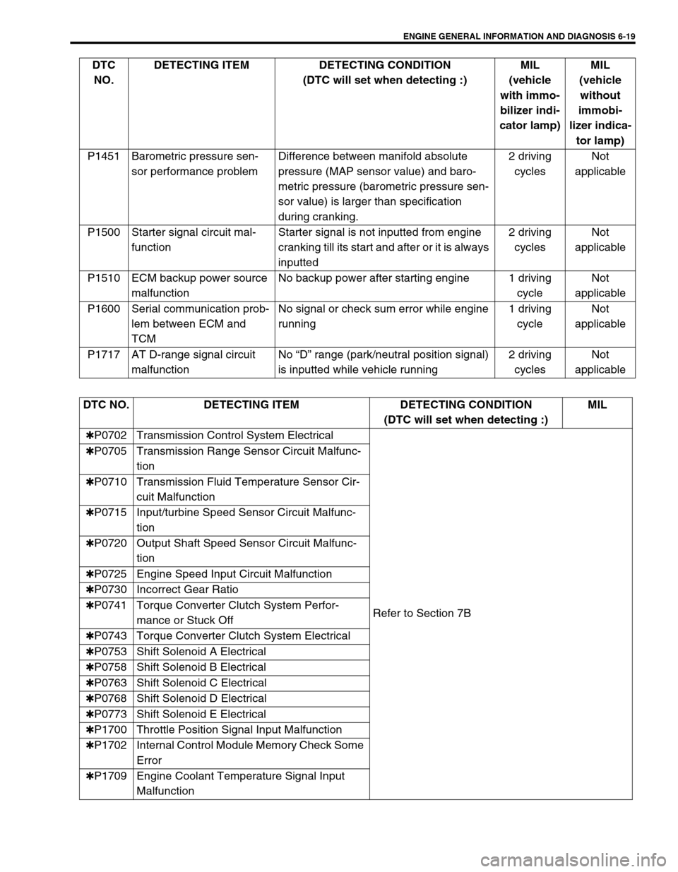
ENGINE GENERAL INFORMATION AND DIAGNOSIS 6-19
P1451 Barometric pressure sen-
sor performance problemDifference between manifold absolute
pressure (MAP sensor value) and baro-
metric pressure (barometric pressure sen-
sor value) is larger than specification
during cranking.2 driving
cyclesNot
applicable
P1500 Starter signal circuit mal-
functionStarter signal is not inputted from engine
cranking till its start and after or it is always
inputted2 driving
cyclesNot
applicable
P1510 ECM backup power source
malfunctionNo backup power after starting engine 1 driving
cycleNot
applicable
P1600 Serial communication prob-
lem between ECM and
TCMNo signal or check sum error while engine
running1 driving
cycleNot
applicable
P1717 AT D-range signal circuit
malfunctionNo “D” range (park/neutral position signal)
is inputted while vehicle running2 driving
cyclesNot
applicable DTC
NO.DETECTING ITEM DETECTING CONDITION
(DTC will set when detecting :)MIL
(vehicle
with immo-
bilizer indi-
cator lamp)MIL
(vehicle
without
immobi-
lizer indica-
tor lamp)
DTC NO. DETECTING ITEM DETECTING CONDITION
(DTC will set when detecting :)MIL
✱P0702 Transmission Control System Electrical
Refer to Section 7B ✱P0705 Transmission Range Sensor Circuit Malfunc-
tion
✱P0710 Transmission Fluid Temperature Sensor Cir-
cuit Malfunction
✱P0715 Input/turbine Speed Sensor Circuit Malfunc-
tion
✱P0720 Output Shaft Speed Sensor Circuit Malfunc-
tion
✱P0725 Engine Speed Input Circuit Malfunction
✱P0730 Incorrect Gear Ratio
✱P0741 Torque Converter Clutch System Perfor-
mance or Stuck Off
✱P0743 Torque Converter Clutch System Electrical
✱P0753 Shift Solenoid A Electrical
✱P0758 Shift Solenoid B Electrical
✱P0763 Shift Solenoid C Electrical
✱P0768 Shift Solenoid D Electrical
✱P0773 Shift Solenoid E Electrical
✱P1700 Throttle Position Signal Input Malfunction
✱P1702 Internal Control Module Memory Check Some
Error
✱P1709 Engine Coolant Temperature Signal Input
Malfunction