heater SUZUKI SWIFT 2000 1.G RG413 Service Service Manual
[x] Cancel search | Manufacturer: SUZUKI, Model Year: 2000, Model line: SWIFT, Model: SUZUKI SWIFT 2000 1.GPages: 698, PDF Size: 16.01 MB
Page 599 of 698
6B-10 ENGINE COOLING
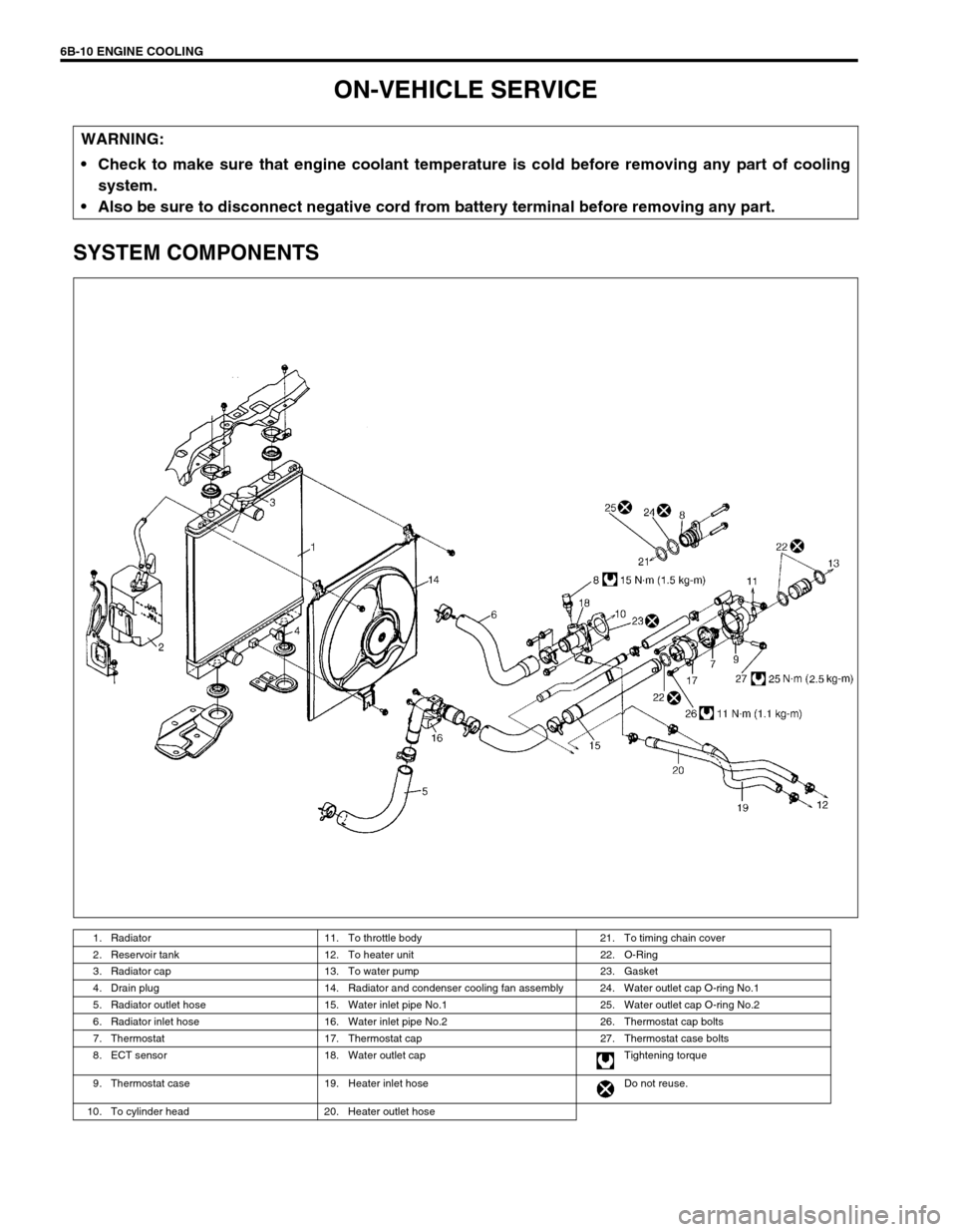
ON-VEHICLE SERVICE
SYSTEM COMPONENTS
WARNING:
Check to make sure that engine coolant temperature is cold before removing any part of cooling
system.
Also be sure to disconnect negative cord from battery terminal before removing any part.
1. Radiator 11. To throttle body 21. To timing chain cover
2. Reservoir tank 12. To heater unit 22. O-Ring
3. Radiator cap 13. To water pump 23. Gasket
4. Drain plug 14. Radiator and condenser cooling fan assembly 24. Water outlet cap O-ring No.1
5. Radiator outlet hose 15. Water inlet pipe No.1 25. Water outlet cap O-ring No.2
6. Radiator inlet hose 16. Water inlet pipe No.2 26. Thermostat cap bolts
7. Thermostat 17. Thermostat cap 27. Thermostat case bolts
8. ECT sensor 18. Water outlet cap Tightening torque
9. Thermostat case 19. Heater inlet hose Do not reuse.
10. To cylinder head 20. Heater outlet hose
Page 601 of 698
6B-12 ENGINE COOLING
COOLING WATER PIPES OR HOSES
REMOVAL
1) Drain cooling system.
2) To remove these pipes or hoses, loosen clamp on each
hose and pull hose end off.
INSTALLATION
Install removed parts in reverse order of removal procedure, not-
ing the following.
Tighten each clamp securely.
Refill cooling system with proper coolant referring to “COOL-
ING SYSTEM REFILL”.
THERMOSTAT
REMOVAL
1) Drain cooling system by loosening drain plug of radiator
referring to “COOLING SYSTEM DRAINING”.
2) Remove air cleaner assembly and resonator referring to sec-
tion 6A1
3) Remove intake manifold referring to Section 6A1.
4) Remove generator referring to Section 6H.
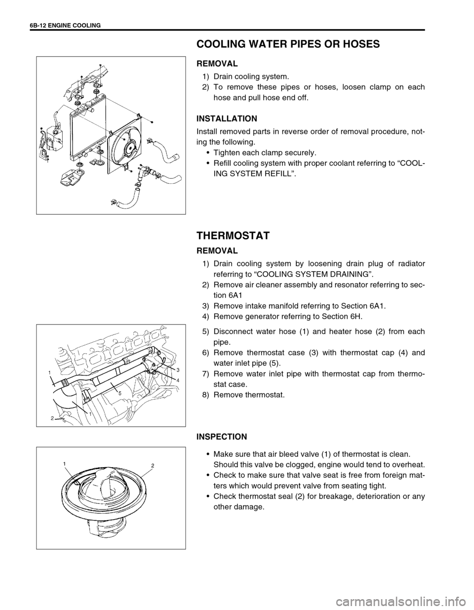
5) Disconnect water hose (1) and heater hose (2) from each
pipe.
6) Remove thermostat case (3) with thermostat cap (4) and
water inlet pipe (5).
7) Remove water inlet pipe with thermostat cap from thermo-
stat case.
8) Remove thermostat.
INSPECTION
Make sure that air bleed valve (1) of thermostat is clean.
Should this valve be clogged, engine would tend to overheat.
Check to make sure that valve seat is free from foreign mat-
ters which would prevent valve from seating tight.
Check thermostat seal (2) for breakage, deterioration or any
other damage.
Page 602 of 698

ENGINE COOLING 6B-13
Check thermostatic movement of wax pellet as follows :
a) Immerse thermostat (1) in water, and heat water gradually.
b) Check that valve starts to open at specific temperature.
Temperature at which valve begins to open
: 80 – 84°C (176 – 183°F)
Temperature at which valve become fully open
: 95 – 97°C (203°F)
Valve lift
: More than 8 mm at 95°C (203°F)
If valve starts to open at a temperature substantially below or
above specific temperature, thermostat unit should be replaced
with a new one. Such a unit, if reused, will bring about overcool-
ing or overheating tendency.
INSTALLATION
Reverse removal procedure for installation noting the following
points.
When positioning thermostat (1) on thermostat case (2), be
sure to position it so that air bleed valve (3) comes at posi-
tion as shown in figure.
Use new O-rings when installing.
Adjust water pump belt tension referring to WATER PUMP/
GENERATOR DRIVE BELT TENSION INSPECTION AND
ADJUSTMENT in this section.
Adjust A/C compressor belt tension (if equipped) referring to
Section 1B.
Refill cooling system with proper coolant referring to “COOL-
ING SYSTEM REFILL”.
Verify that there is no coolant leakage at each connection.
2. Thermometer
3. Heater
Page 610 of 698
ENGINE FUEL 6C-3
PRECAUTIONS
WARNING:
Before attempting service of any type on fuel system, the
followings should be always observed in order to reduce
the risk or fire and personal injury.
Disconnect negative cable at battery.
Do not smoke, and place no smoking signs near work
area.
Be sure to have CO
2 fire extinguisher handy.
Be sure to perform work in a well-ventilated area and
away from any open flames (such as gas hot heater).
Wear safety glasses.
To relieve fuel vapor pressure in fuel tank, remove fuel
filler cap from fuel filler neck and then reinstall it.
As fuel feed line is still under high fuel pressure even
after engine was stopped, loosening or disconnecting
fuel feed line directly may cause dangerous spout of
fuel to occur where loosened or disconnected.
Before loosening or disconnecting fuel feed line, make
sure to relieve fuel pressure “FUEL PRESSURE
RELIEF PROCEDURE” in Section 6.
A small amount of fuel may be released after the fuel
line is disconnected. In order to reduce the chance of
personal injury, cover the fitting to be disconnected
with a shop cloth. Be sure to put that cloth in an
approved container when disconnection is completed.
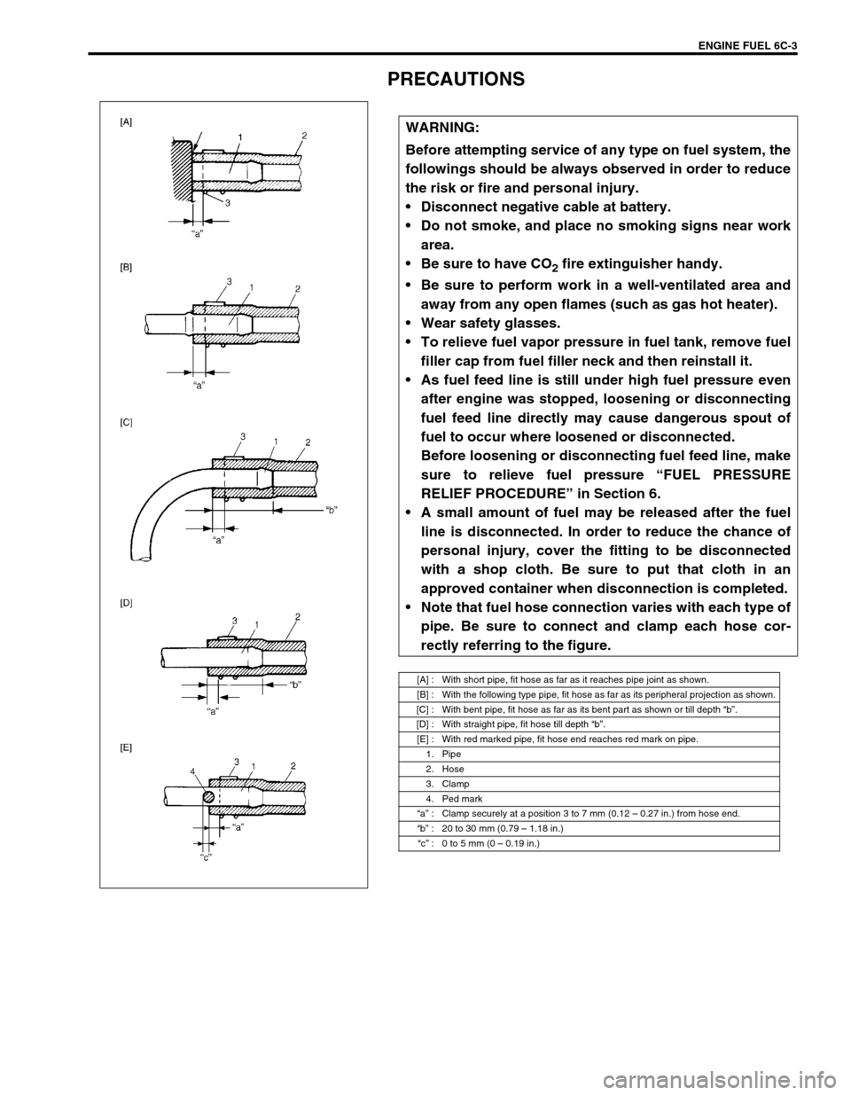
Note that fuel hose connection varies with each type of
pipe. Be sure to connect and clamp each hose cor-
rectly referring to the figure.
[A] : With short pipe, fit hose as far as it reaches pipe joint as shown.
[B] : With the following type pipe, fit hose as far as its peripheral projection as shown.
[C] : With bent pipe, fit hose as far as its bent part as shown or till depth “b”.
[D] : With straight pipe, fit hose till depth “b”.
[E] : With red marked pipe, fit hose end reaches red mark on pipe.
1. Pipe
2. Hose
3. Clamp
4. Ped mark
“a” : Clamp securely at a position 3 to 7 mm (0.12 – 0.27 in.) from hose end.
“b” : 20 to 30 mm (0.79 – 1.18 in.)
“c” : 0 to 5 mm (0 – 0.19 in.)
Page 628 of 698

ENGINE AND EMISSION CONTROL SYSTEM 6E1-7
ELECTRONIC CONTROL SYSTEM
The electronic control system consists of 1) various sensors which detect the state of engine and driving condi-
tions, 2) ECM which controls various devices according to the signals from the sensors and 3) various controlled
devices.
Functionally, it is divided into nine sub systems :
Fuel injection control system
Idle speed control system
Fuel pump control system
A/C control system (if equipped)
Radiator fan control system
EGR system (if equipped)
Evaporative emission control system
Oxygen sensor heater control system (if equipped)
Ignition control system
Also, with A/T model, ECM sends throttle valve opening signal and coolant temp. signal to transmission control
module to control A/T.
INFORMATION SENSORS CONTROL DEVICES OTHERS
1. MAP sensor a : Fuel injector A : ECM
2. TP sensor b : EVAP canister purge valve B : Main relay
3. IAT sensor c : Fuel pump relay C : EVAP canister
4. ECT sensor d : EGR valve (step motor) (if equipped) D : Monitor connector
5. Heated oxygen sensor-1 (if equipped) e : Malfunction indicator lamp E : Data link connector
5-1. Heated oxygen sensor-2 (if equipped) f : Ignition coil assembly F : A/C EVAP thermistor (if equipped)
6. VSS g : Radiator fan control relay G : TCM (A/T)
7. Transmission range switch (A/T) h : IAC valve
8. Battery i : Immobilizer indicator lamp
9. CMP sensor
10. CKP sensor
11. Fuel level sensor (gauge) (in fuel tank)
12. Stop lamp switch
13. Knock sensor (if equipped)
Page 629 of 698
6E1-8 ENGINE AND EMISSION CONTROL SYSTEM
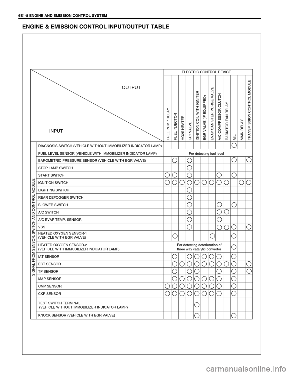
ENGINE & EMISSION CONTROL INPUT/OUTPUT TABLE
INPUTOUTPUT
ELECTRIC CONTROL DEVICE
FUEL LEVEL SENSOR (VEHICLE WITH IMMOBILIZER INDICATOR LAMP) For detecting fuel level DIAGNOSIS SWITCH (VEHICLE WITHOUT IMMOBILIZER INDICATOR LAMP)
BAROMETRIC PRESSURE SENSOR (VEHICLE WITH EGR VALVE)
STOP LAMP SWITCH
START SWITCH
IGNITION SWITCH
LIGHTING SWITCH
REAR DEFOGGER SWITCH
BLOWER SWITCH
A/C SWITCH
A/C EVAP TEMP. SENSOR
VSS
HEATED OXYGEN SENSOR-1
(VEHICLE WITH EGR VALVE)
HEATED OXYGEN SENSOR-2
(VEHICLE WITH IMMOBILIZER INDICATOR LAMP)For detecting deterioration of
three way catalytic convertor
IAT SENSOR
ECT SENSOR
TP SENSOR
MAP SENSOR
CMP SENSOR
CKP SENSOR
TEST SWITCH TERMINAL
(VEHICLE WITHOUT IMMOBILIZER INDICATOR LAMP)
KNOCK SENSOR (VEHICLE WITH EGR VALVE)
FUEL PUMP RELAY
FUEL INJECTOR
HO2S HEATER
IAC VALVE
IGNITION COIL WITH IGNITER
EGR VALVE (IF EQUIPPED)
EVAP CANISTER PURGE VALVE
A/C COMPRESSOR CLUTCH
RADIATOR FAN RELAY
MIL
MAIN RELAY
TRANSMISSION CONTROL MODULE SIGNAL FROM SENSOR, SWITCH AND CONTROL MODULE
Page 631 of 698
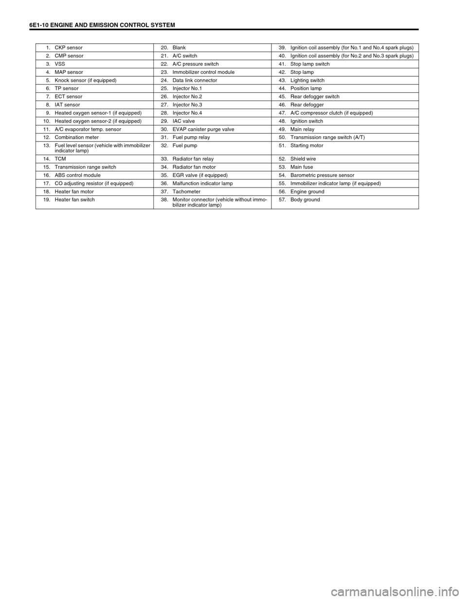
6E1-10 ENGINE AND EMISSION CONTROL SYSTEM
1. CKP sensor 20. Blank 39. Ignition coil assembly (for No.1 and No.4 spark plugs)
2. CMP sensor 21. A/C switch 40. Ignition coil assembly (for No.2 and No.3 spark plugs)
3. VSS 22. A/C pressure switch 41. Stop lamp switch
4. MAP sensor 23. Immobilizer control module 42. Stop lamp
5. Knock sensor (if equipped) 24. Data link connector 43. Lighting switch
6. TP sensor 25. Injector No.1 44. Position lamp
7. ECT sensor 26. Injector No.2 45. Rear defogger switch
8. IAT sensor 27. Injector No.3 46. Rear defogger
9. Heated oxygen sensor-1 (if equipped) 28. Injector No.4 47. A/C compressor clutch (if equipped)
10. Heated oxygen sensor-2 (if equipped) 29. IAC valve 48. Ignition switch
11. A/C evaporator temp. sensor 30. EVAP canister purge valve 49. Main relay
12. Combination meter 31. Fuel pump relay 50. Transmission range switch (A/T)
13. Fuel level sensor (vehicle with immobilizer
indicator lamp)32. Fuel pump 51. Starting motor
14. TCM 33. Radiator fan relay 52. Shield wire
15. Transmission range switch 34. Radiator fan motor 53. Main fuse
16. ABS control module 35. EGR valve (if equipped) 54. Barometric pressure sensor
17. CO adjusting resistor (if equipped) 36. Malfunction indicator lamp 55. Immobilizer indicator lamp (if equipped)
18. Heater fan motor 37. Tachometer 56. Engine ground
19. Heater fan switch 38. Monitor connector (vehicle without immo-
bilizer indicator lamp)57. Body ground
Page 633 of 698
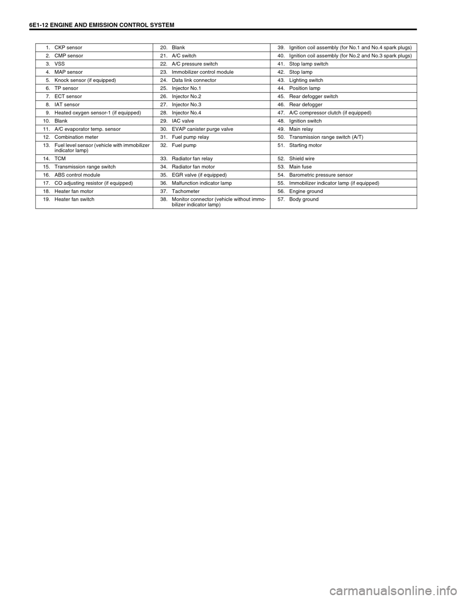
6E1-12 ENGINE AND EMISSION CONTROL SYSTEM
1. CKP sensor 20. Blank 39. Ignition coil assembly (for No.1 and No.4 spark plugs)
2. CMP sensor 21. A/C switch 40. Ignition coil assembly (for No.2 and No.3 spark plugs)
3. VSS 22. A/C pressure switch 41. Stop lamp switch
4. MAP sensor 23. Immobilizer control module 42. Stop lamp
5. Knock sensor (if equipped) 24. Data link connector 43. Lighting switch
6. TP sensor 25. Injector No.1 44. Position lamp
7. ECT sensor 26. Injector No.2 45. Rear defogger switch
8. IAT sensor 27. Injector No.3 46. Rear defogger
9. Heated oxygen sensor-1 (if equipped) 28. Injector No.4 47. A/C compressor clutch (if equipped)
10. Blank 29. IAC valve 48. Ignition switch
11. A/C evaporator temp. sensor 30. EVAP canister purge valve 49. Main relay
12. Combination meter 31. Fuel pump relay 50. Transmission range switch (A/T)
13. Fuel level sensor (vehicle with immobilizer
indicator lamp)32. Fuel pump 51. Starting motor
14. TCM 33. Radiator fan relay 52. Shield wire
15. Transmission range switch 34. Radiator fan motor 53. Main fuse
16. ABS control module 35. EGR valve (if equipped) 54. Barometric pressure sensor
17. CO adjusting resistor (if equipped) 36. Malfunction indicator lamp 55. Immobilizer indicator lamp (if equipped)
18. Heater fan motor 37. Tachometer 56. Engine ground
19. Heater fan switch 38. Monitor connector (vehicle without immo-
bilizer indicator lamp)57. Body ground
Page 634 of 698
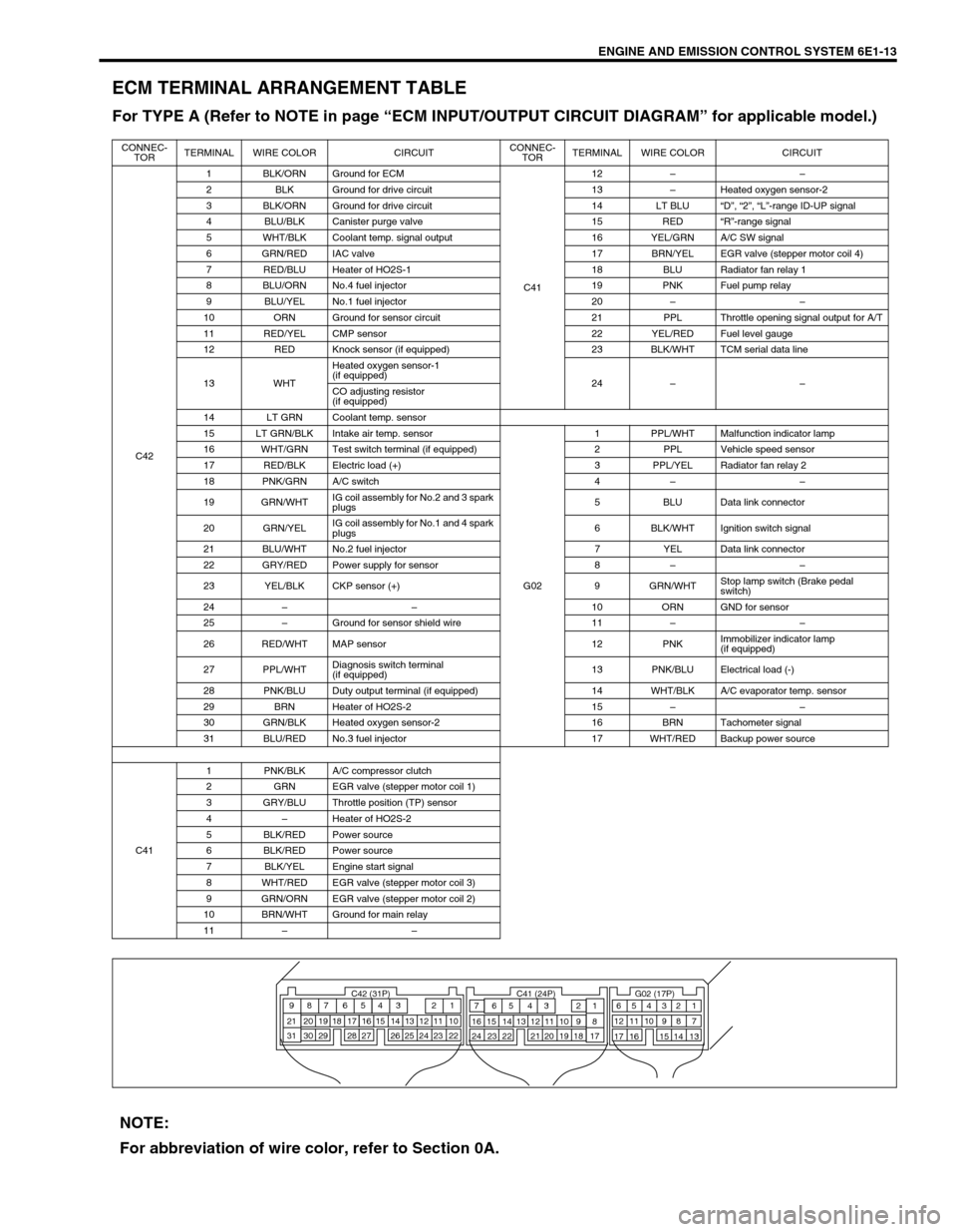
ENGINE AND EMISSION CONTROL SYSTEM 6E1-13
ECM TERMINAL ARRANGEMENT TABLE
For TYPE A (Refer to NOTE in page “ECM INPUT/OUTPUT CIRCUIT DIAGRAM” for applicable model.)
CONNEC-
TORTERMINAL WIRE COLOR CIRCUITCONNEC-
TORTERMINAL WIRE COLOR CIRCUIT
C421 BLK/ORN Ground for ECM
C4112––
2 BLK Ground for drive circuit 13–Heated oxygen sensor-2
3 BLK/ORN Ground for drive circuit 14 LT BLU“D”, “2”, “L”-range ID-UP signal
4 BLU/BLK Canister purge valve 15 RED“R”-range signal
5 WHT/BLK Coolant temp. signal output 16 YEL/GRN A/C SW signal
6 GRN/RED IAC valve 17 BRN/YEL EGR valve (stepper motor coil 4)
7 RED/BLU Heater of HO2S-1 18 BLU Radiator fan relay 1
8 BLU/ORN No.4 fuel injector 19 PNK Fuel pump relay
9 BLU/YEL No.1 fuel injector 20––
10 ORN Ground for sensor circuit 21 PPL Throttle opening signal output for A/T
11 RED/YEL CMP sensor 22 YEL/RED Fuel level gauge
12 RED Knock sensor (if equipped) 23 BLK/WHT TCM serial data line
13 WHTHeated oxygen sensor-1
(if equipped)
24––
CO adjusting resistor
(if equipped)
14 LT GRN Coolant temp. sensor
15 LT GRN/BLK Intake air temp. sensor
G021 PPL/WHT Malfunction indicator lamp
16 WHT/GRN Test switch terminal (if equipped) 2 PPL Vehicle speed sensor
17 RED/BLK Electric load (+) 3 PPL/YEL Radiator fan relay 2
18 PNK/GRN A/C switch 4––
19 GRN/WHTIG coil assembly for No.2 and 3 spark
plugs5 BLU Data link connector
20 GRN/YELIG coil assembly for No.1 and 4 spark
plugs6 BLK/WHT Ignition switch signal
21 BLU/WHT No.2 fuel injector 7 YEL Data link connector
22 GRY/RED Power supply for sensor 8––
23 YEL/BLK CKP sensor (+) 9 GRN/WHTStop lamp switch (Brake pedal
switch)
24––10 ORN GND for sensor
25–Ground for sensor shield wire 11––
26 RED/WHT MAP sensor 12 PNKImmobilizer indicator lamp
(if equipped)
27 PPL/WHTDiagnosis switch terminal
(if equipped)13 PNK/BLU Electrical load (-)
28 PNK/BLU Duty output terminal (if equipped) 14 WHT/BLK A/C evaporator temp. sensor
29 BRN Heater of HO2S-2 15––
30 GRN/BLK Heated oxygen sensor-2 16 BRN Tachometer signal
31 BLU/RED No.3 fuel injector 17 WHT/RED Backup power source
C411 PNK/BLK A/C compressor clutch
2 GRN EGR valve (stepper motor coil 1)
3 GRY/BLU Throttle position (TP) sensor
4–Heater of HO2S-2
5 BLK/RED Power source
6 BLK/RED Power source
7 BLK/YEL Engine start signal
8 WHT/RED EGR valve (stepper motor coil 3)
9 GRN/ORN EGR valve (stepper motor coil 2)
10 BRN/WHT Ground for main relay
11––
C42 (31P) C41 (24P) G02 (17P)1 2 3 4 5 6 7 8 9
10 11 12 13 14 15 16 17 18 19 20 21
22 23 24 25 26 28 27 29 30 315 6
1 2 3 4 5 6 7
11 12
9 10 11 13 12 14 15 16
16 171 2
7 8
13 14 3 4
9 10
15 17 188
19 20 21 22 23 24
NOTE:
For abbreviation of wire color, refer to Section 0A.
Page 635 of 698
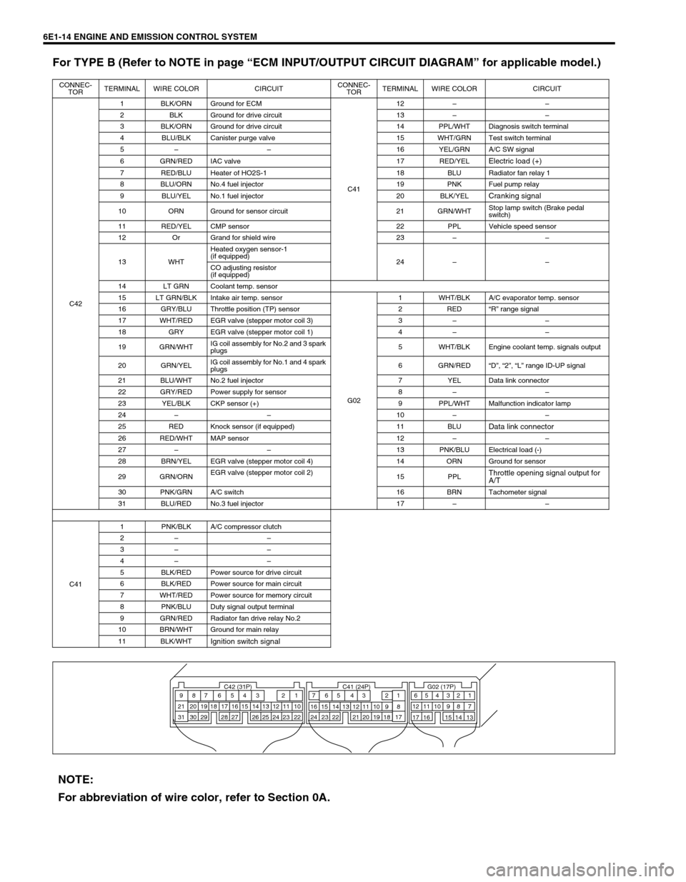
6E1-14 ENGINE AND EMISSION CONTROL SYSTEM
For TYPE B (Refer to NOTE in page “ECM INPUT/OUTPUT CIRCUIT DIAGRAM” for applicable model.)
CONNEC-
TORTERMINAL WIRE COLOR CIRCUITCONNEC-
TORTERMINAL WIRE COLOR CIRCUIT
C421 BLK/ORN Ground for ECM
C4112––
2 BLK Ground for drive circuit 13––
3 BLK/ORN Ground for drive circuit 14 PPL/WHT Diagnosis switch terminal
4 BLU/BLK Canister purge valve 15 WHT/GRN Test switch terminal
5––16 YEL/GRN A/C SW signal
6 GRN/RED IAC valve 17 RED/YEL
Electric load (+)
7 RED/BLU Heater of HO2S-1 18 BLU Radiator fan relay 1
8 BLU/ORN No.4 fuel injector 19 PNK Fuel pump relay
9 BLU/YEL No.1 fuel injector 20 BLK/YEL
Cranking signal
10 ORN Ground for sensor circuit 21 GRN/WHTStop lamp switch (Brake pedal
switch)
11 RED/YEL CMP sensor 22 PPL Vehicle speed sensor
12 Or Grand for shield wire 23––
13 WHTHeated oxygen sensor-1
(if equipped)
24––
CO adjusting resistor
(if equipped)
14 LT GRN Coolant temp. sensor
15 LT GRN/BLK Intake air temp. sensor
G021 WHT/BLK A/C evaporator temp. sensor
16 GRY/BLU Throttle position (TP) sensor 2 RED“R” range signal
17 WHT/RED EGR valve (stepper motor coil 3) 3––
18 GRY EGR valve (stepper motor coil 1) 4––
19 GRN/WHTIG coil assembly for No.2 and 3 spark
plugs5 WHT/BLK Engine coolant temp. signals output
20 GRN/YELIG coil assembly for No.1 and 4 spark
plugs6 GRN/RED“D”, “2”, “L” range ID-UP signal
21 BLU/WHT No.2 fuel injector 7 YEL Data link connector
22 GRY/RED Power supply for sensor 8––
23 YEL/BLK CKP sensor (+) 9 PPL/WHT Malfunction indicator lamp
24––10––
25 RED Knock sensor (if equipped) 11 BLU
Data link connector
26 RED/WHT MAP sensor 12––
27––13 PNK/BLU Electrical load (-)
28 BRN/YEL EGR valve (stepper motor coil 4) 14 ORN Ground for sensor
29 GRN/ORNEGR valve (stepper motor coil 2)
15 PPL
Throttle opening signal output for
A/T
30 PNK/GRN A/C switch 16 BRN Tachometer signal
31 BLU/RED No.3 fuel injector 17––
C411 PNK/BLK A/C compressor clutch
2––
3––
4––
5 BLK/RED Power source for drive circuit
6 BLK/RED Power source for main circuit
7 WHT/RED Power source for memory circuit
8 PNK/BLU Duty signal output terminal
9 GRN/RED Radiator fan drive relay No.2
10 BRN/WHT Ground for main relay
11 BLK/WHT
Ignition switch signal
C42 (31P) C41 (24P) G02 (17P)1 2 3 4 5 6 7 8 9
10 11 12 13 14 15 16 17 18 19 20 21
22 23 24 25 26 28 27 29 30 315 6
1 2 3 4 5 6 7
11 12
9 10 11 13 12 14 15 16
16 171 2
7 8
13 14 3 4
9 10
15 17 188
19 20 21 22 23 24
NOTE:
For abbreviation of wire color, refer to Section 0A.