heater SUZUKI SWIFT 2000 1.G RG413 Service User Guide
[x] Cancel search | Manufacturer: SUZUKI, Model Year: 2000, Model line: SWIFT, Model: SUZUKI SWIFT 2000 1.GPages: 698, PDF Size: 16.01 MB
Page 58 of 698
HEATER AND VENTILATION 1A-7
BLOWER FAN MOTOR
REMOVAL
1) Disconnect negative (–) cable at battery.
2) Remove steering column hole cover.
3) Remove brake and clutch pedals bracket from vehicle body.
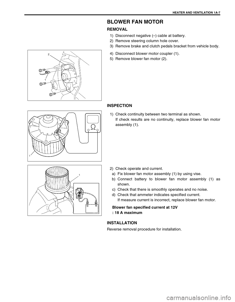
4) Disconnect blower motor coupler (1).
5) Remove blower fan motor (2).
INSPECTION
1) Check continuity between two terminal as shown.
If check results are no continuity, replace blower fan motor
assembly (1).
2) Check operate and current.
a) Fix blower fan motor assembly (1) by using vise.
b) Connect battery to blower fan motor assembly (1) as
shown.
c) Check that there is smoothly operates and no noise.
d) Check that ammeter indicates specified current.
If measure current is incorrect, replace blower fan motor.
Blower fan specified current at 12V
: 18 A maximum
INSTALLATION
Reverse removal procedure for installation.
Page 59 of 698
1A-8 HEATER AND VENTILATION
BLOWER FAN MOTOR RESISTOR
REMOVAL
1) Disconnect negative (–) cable at battery.
2) Disconnect blower fan motor resistor coupler.
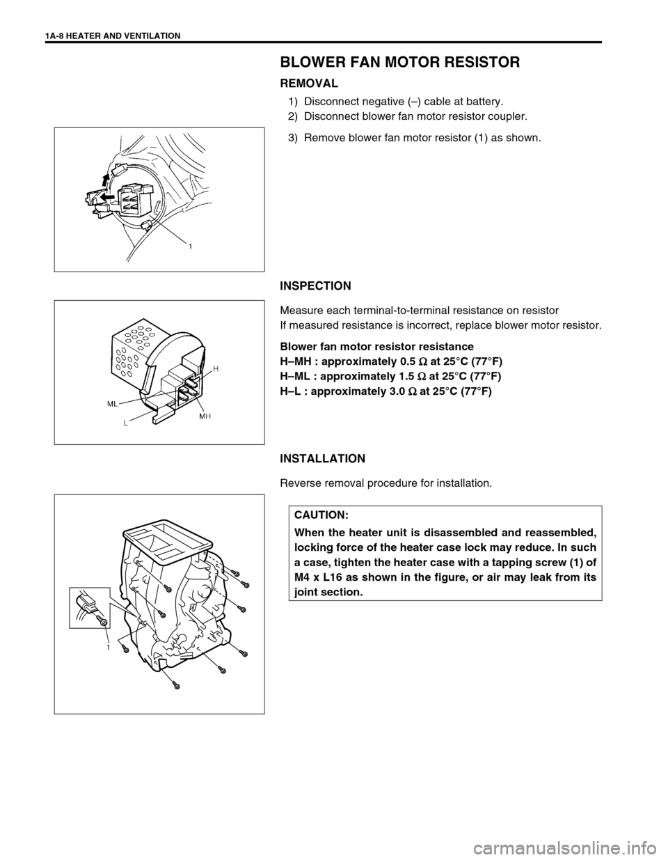
3) Remove blower fan motor resistor (1) as shown.
INSPECTION
Measure each terminal-to-terminal resistance on resistor
If measured resistance is incorrect, replace blower motor resistor.
Blower fan motor resistor resistance
H–MH : approximately 0.5
Ω
ΩΩ Ω at 25°C (77°F)
H–ML : approximately 1.5
Ω
ΩΩ Ω at 25°C (77°F)
H–L : approximately 3.0
Ω
ΩΩ Ω at 25°C (77°F)
INSTALLATION
Reverse removal procedure for installation.
CAUTION:
When the heater unit is disassembled and reassembled,
locking force of the heater case lock may reduce. In such
a case, tighten the heater case with a tapping screw (1) of
M4 x L16 as shown in the figure, or air may leak from its
joint section.
1
Page 60 of 698
HEATER AND VENTILATION 1A-9
HEATER CONTROL ASSEMBLY
REMOVAL
1) Disconnect negative (–) cable at battery.
2) Remove steering column hole cover.
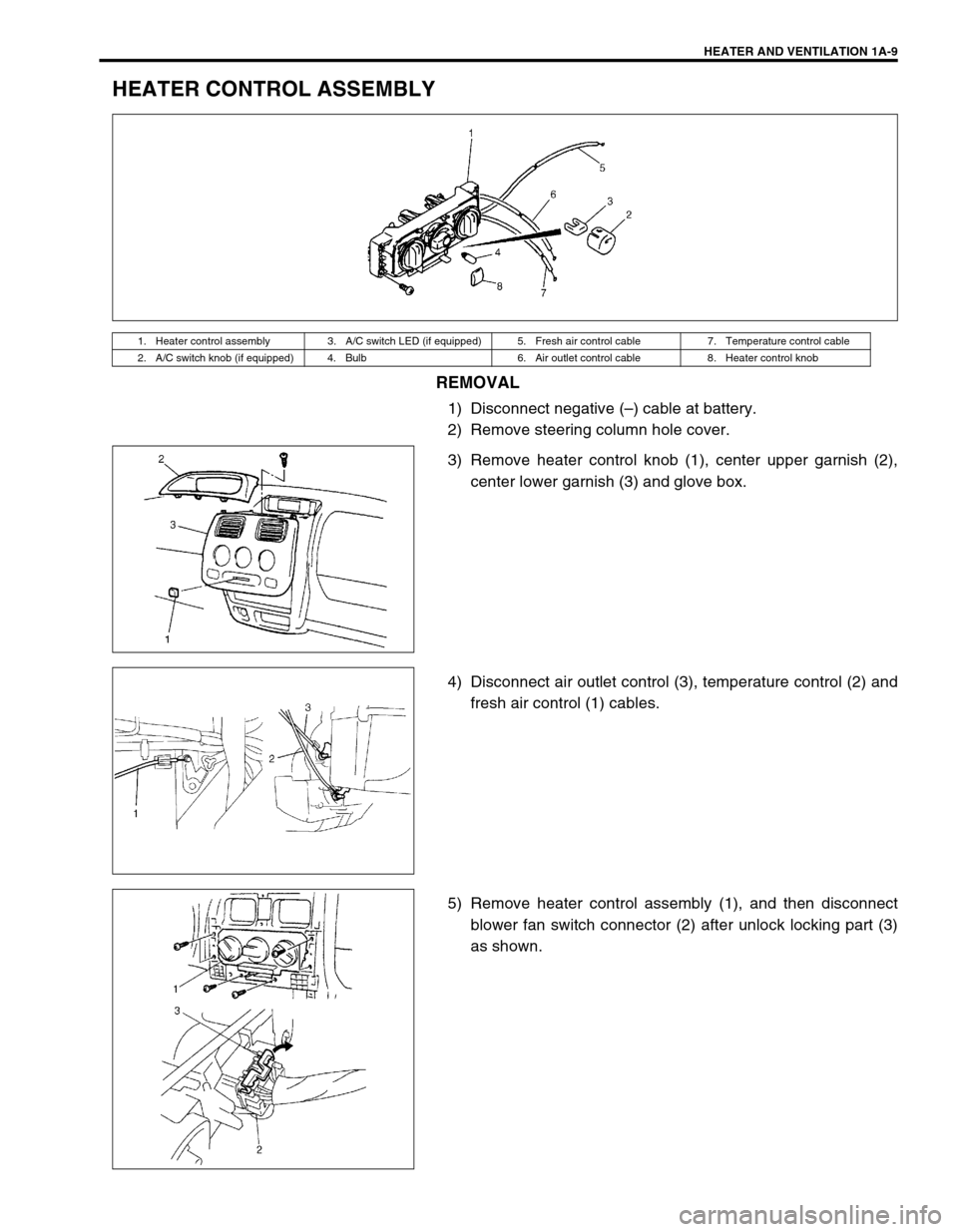
3) Remove heater control knob (1), center upper garnish (2),
center lower garnish (3) and glove box.
4) Disconnect air outlet control (3), temperature control (2) and
fresh air control (1) cables.
5) Remove heater control assembly (1), and then disconnect
blower fan switch connector (2) after unlock locking part (3)
as shown.
1. Heater control assembly 3. A/C switch LED (if equipped) 5. Fresh air control cable 7. Temperature control cable
2. A/C switch knob (if equipped) 4. Bulb 6. Air outlet control cable 8. Heater control knob
Page 61 of 698
1A-10 HEATER AND VENTILATION
INSTALLATION
1) Reverse removal procedure for installation.
2) Adjust the following items.
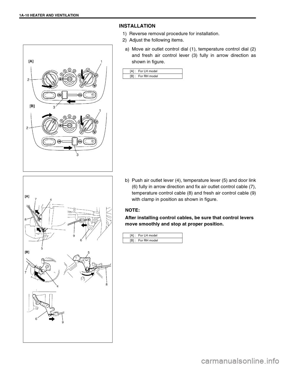
a) Move air outlet control dial (1), temperature control dial (2)
and fresh air control lever (3) fully in arrow direction as
shown in figure.
b) Push air outlet lever (4), temperature lever (5) and door link
(6) fully in arrow direction and fix air outlet control cable (7),
temperature control cable (8) and fresh air control cable (9)
with clamp in position as shown in figure.
[A] : For LH model
[B] : For RH model
NOTE:
After installing control cables, be sure that control levers
move smoothly and stop at proper position.
[A] : For LH model
[B] : For RH model
Page 62 of 698
HEATER AND VENTILATION 1A-11
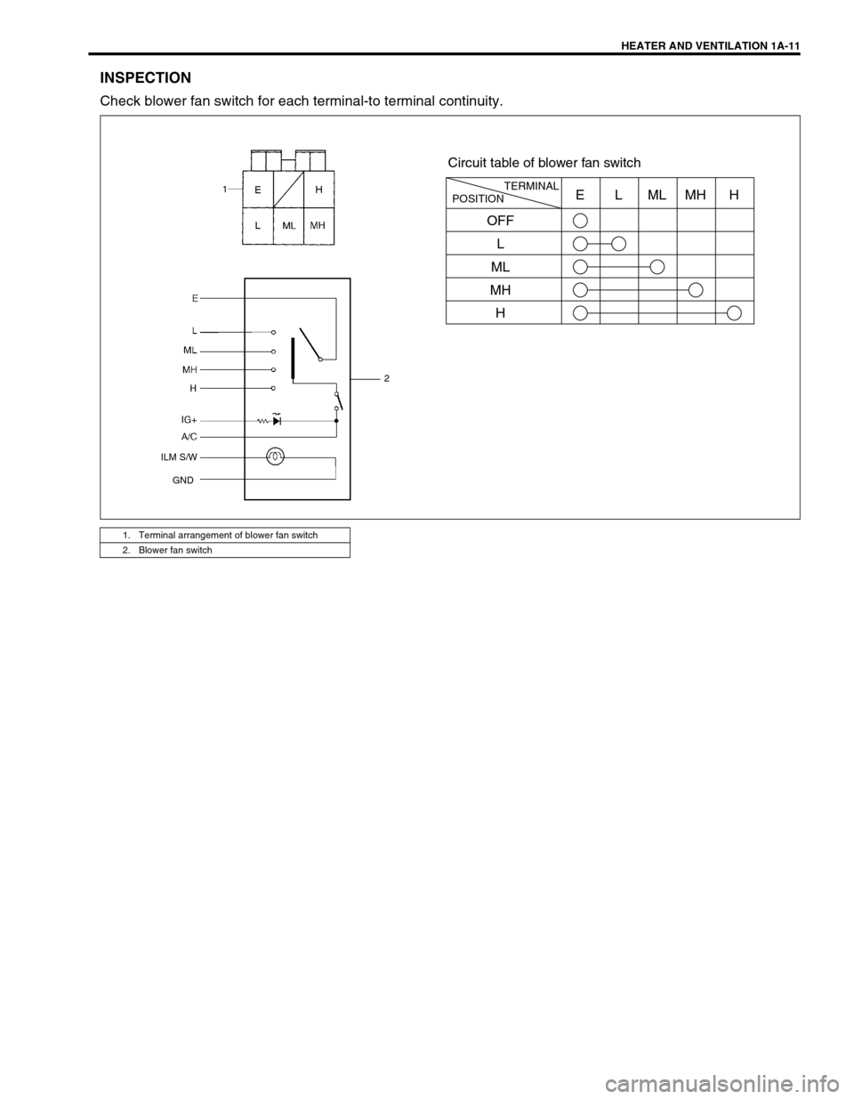
INSPECTION
Check blower fan switch for each terminal-to terminal continuity.
1. Terminal arrangement of blower fan switch
2. Blower fan switch
POSITIONTERMINALE
OFF
L
ML
MH
HLMLMHH
Circuit table of blower fan switch
1
2
ILM S/W
GND
1
Page 63 of 698
1A-12 HEATER AND VENTILATION
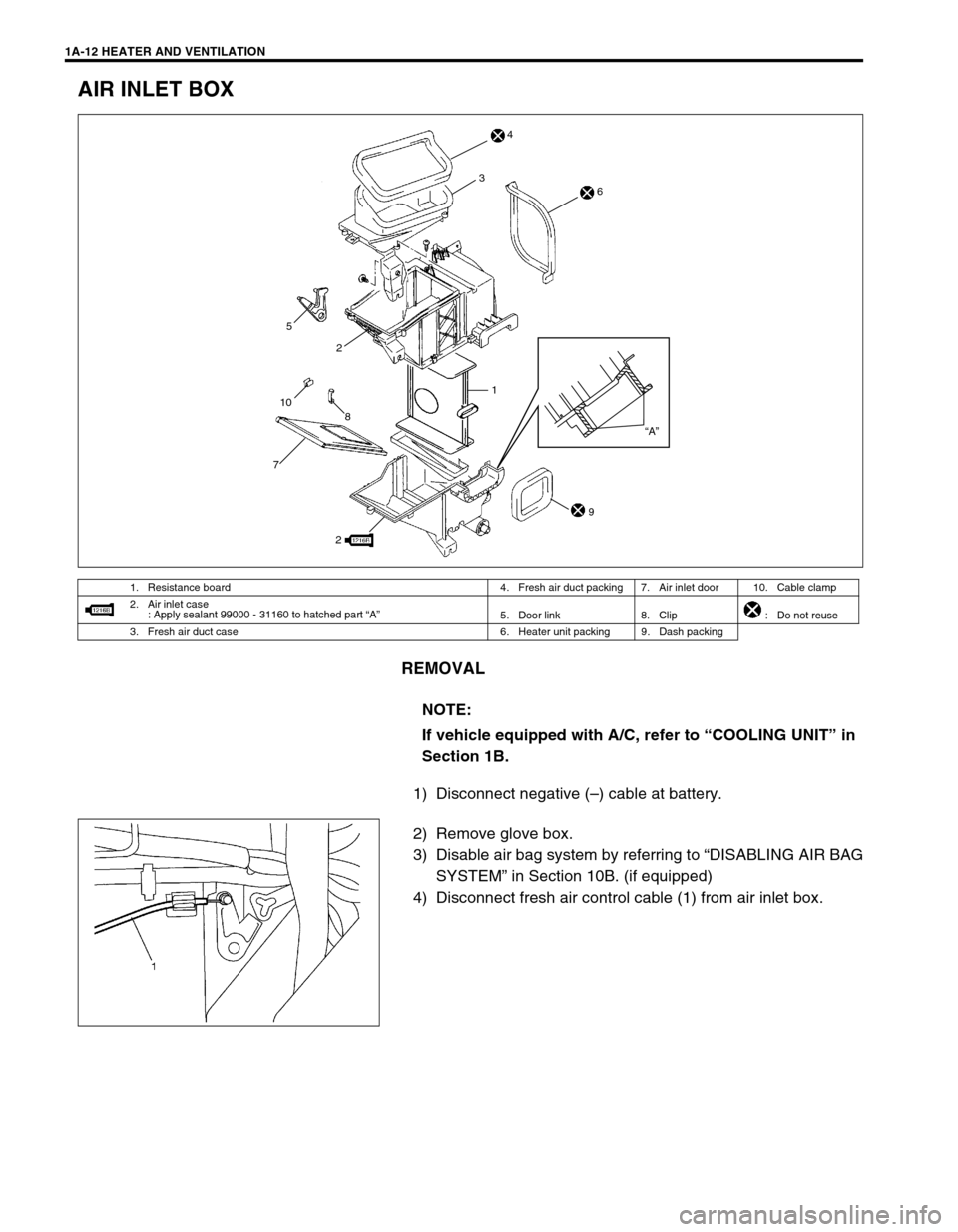
AIR INLET BOX
REMOVAL
1) Disconnect negative (–) cable at battery.
2) Remove glove box.
3) Disable air bag system by referring to “DISABLING AIR BAG
SYSTEM” in Section 10B. (if equipped)
4) Disconnect fresh air control cable (1) from air inlet box.
1. Resistance board 4. Fresh air duct packing 7. Air inlet door 10. Cable clamp
2. Air inlet case
: Apply sealant 99000 - 31160 to hatched part “A”
5. Door link 8. Clip : Do not reuse
3. Fresh air duct case 6. Heater unit packing 9. Dash packing
NOTE:
If vehicle equipped with A/C, refer to “COOLING UNIT” in
Section 1B.
1
72
8 1053
“A”
2
4
6
9
Page 64 of 698

HEATER AND VENTILATION 1A-13
5) Remove air inlet box mounting nuts (1) and screws (2).
6) Remove air inlet box (3).
INSTALLATION
Reverse removal procedure to install air inlet box noting the fol-
lowing instructions.
Adjust fresh air control cable referring to “INSTALLATION”
under “HEATER CONTROL ASSEMBLY” in this section.
Enable air bag system by referring to “ENABLING AIR BAG
SYSTEM” in Section 10B. (if equipped)
VENTILATION LOUVER
REMOVAL
1) Remove ventilation louver (1) as shown in figure.
2) Remove ventilation louver holder (1) from ventilation louver
(2).
2: Rag
Page 65 of 698

1A-14 HEATER AND VENTILATION
INSTALLATION
Reverse removal procedure to install ventilation louver noting the
following instruction.
Be sure to install ventilation louver holder (1) to proper direc-
tion as shown.
REQUIRED SERVICE MATERIALS
MaterialRecommended SUZUKI product
(Part Number)Use
SealantSUZUKI BOND No. 1216B
99000 – 31160Air inlet box
Page 69 of 698

1B-4 AIR CONDITIONING (OPTIONAL)
MAJOR COMPONENTS AND LOCATION
1. Cooling unit 7. Condenser outlet pipe 13. Demister air 19. High pressure charge valve
2. Compressor 8. Liquid pipe 14. Fresh air 20. Sight glass
3. Condenser assembly 9. Expansion valve 15. Recirculation air [A] : LH model
4. Receiver/dryer 10. Ventilation air 16. Heater unit [B] : RH model
5. Discharge hose 11. Foot air 17. A/C refrigerant pressure switch
6. Suction pipe 12. Defroster air 18. Low pressure charge valve
Page 71 of 698
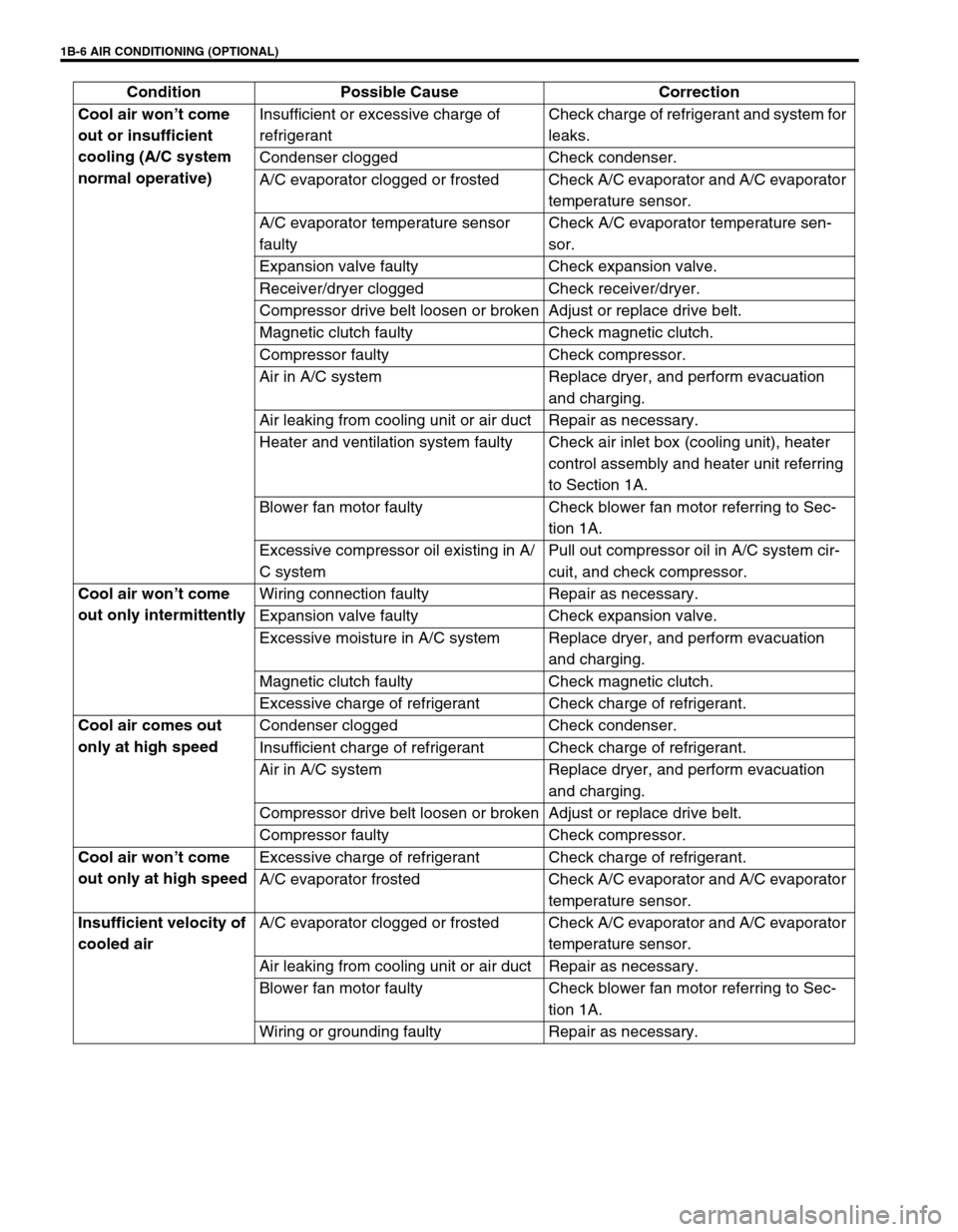
1B-6 AIR CONDITIONING (OPTIONAL)
Cool air won’t come
out or insufficient
cooling (A/C system
normal operative)Insufficient or excessive charge of
refrigerantCheck charge of refrigerant and system for
leaks.
Condenser clogged Check condenser.
A/C evaporator clogged or frosted Check A/C evaporator and A/C evaporator
temperature sensor.
A/C evaporator temperature sensor
faultyCheck A/C evaporator temperature sen-
sor.
Expansion valve faulty Check expansion valve.
Receiver/dryer clogged Check receiver/dryer.
Compressor drive belt loosen or broken Adjust or replace drive belt.
Magnetic clutch faulty Check magnetic clutch.
Compressor faulty Check compressor.
Air in A/C system Replace dryer, and perform evacuation
and charging.
Air leaking from cooling unit or air duct Repair as necessary.
Heater and ventilation system faulty Check air inlet box (cooling unit), heater
control assembly and heater unit referring
to Section 1A.
Blower fan motor faulty Check blower fan motor referring to Sec-
tion 1A.
Excessive compressor oil existing in A/
C systemPull out compressor oil in A/C system cir-
cuit, and check compressor.
Cool air won’t come
out only intermittentlyWiring connection faulty Repair as necessary.
Expansion valve faulty Check expansion valve.
Excessive moisture in A/C system Replace dryer, and perform evacuation
and charging.
Magnetic clutch faulty Check magnetic clutch.
Excessive charge of refrigerant Check charge of refrigerant.
Cool air comes out
only at high speedCondenser clogged Check condenser.
Insufficient charge of refrigerant Check charge of refrigerant.
Air in A/C system Replace dryer, and perform evacuation
and charging.
Compressor drive belt loosen or broken Adjust or replace drive belt.
Compressor faulty Check compressor.
Cool air won’t come
out only at high speedExcessive charge of refrigerant Check charge of refrigerant.
A/C evaporator frosted Check A/C evaporator and A/C evaporator
temperature sensor.
Insufficient velocity of
cooled airA/C evaporator clogged or frosted Check A/C evaporator and A/C evaporator
temperature sensor.
Air leaking from cooling unit or air duct Repair as necessary.
Blower fan motor faulty Check blower fan motor referring to Sec-
tion 1A.
Wiring or grounding faulty Repair as necessary. Condition Possible Cause Correction