Air Condition SUZUKI SWIFT 2000 1.G RG413 Service Manual PDF
[x] Cancel search | Manufacturer: SUZUKI, Model Year: 2000, Model line: SWIFT, Model: SUZUKI SWIFT 2000 1.GPages: 698, PDF Size: 16.01 MB
Page 161 of 698
3B1-20 ELECTRICAL POWER STEERING (P/S) SYSTEM
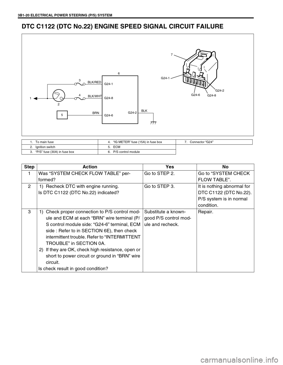
DTC C1122 (DTC No.22) ENGINE SPEED SIGNAL CIRCUIT FAILURE
1. To main fuse 4.“IG METER” fuse (15A) in fuse box 7. Connector “G24”
2. Ignition switch 5. ECM
3.“P/S” fuse (30A) in fuse box 6. P/S control module
G24-2 G24-1
G24-8
G24-6 1
23
4
56
BLK/WHT BLK/RED
BRNBLK
G24-1
G24-6
G24-8G24-2
7
Step Action Yes No
1Was “SYSTEM CHECK FLOW TABLE” per-
formed?Go to STEP 2. Go to “SYSTEM CHECK
FLOW TABLE”.
2 1) Recheck DTC with engine running.
Is DTC C1122 (DTC No.22) indicated?Go to STEP 3. It is nothing abnormal for
DTC C1122 (DTC No.22).
P/S system is in normal
condition.
3 1) Check proper connection to P/S control mod-
ule and ECM at each “BRN” wire terminal (P/
S control module side: “G24-6” terminal, ECM
side : Refer to in SECTION 6E), then check
intermittent trouble. Refer to “INTERMITTENT
TROUBLE” in SECTION 0A.
2) If they are OK, check high resistance, open or
short to power circuit or ground in “BRN” wire
circuit.
Is check result in good condition?Substitute a known-
good P/S control mod-
ule and recheck.Repair.
Page 162 of 698
ELECTRICAL POWER STEERING (P/S) SYSTEM 3B1-21
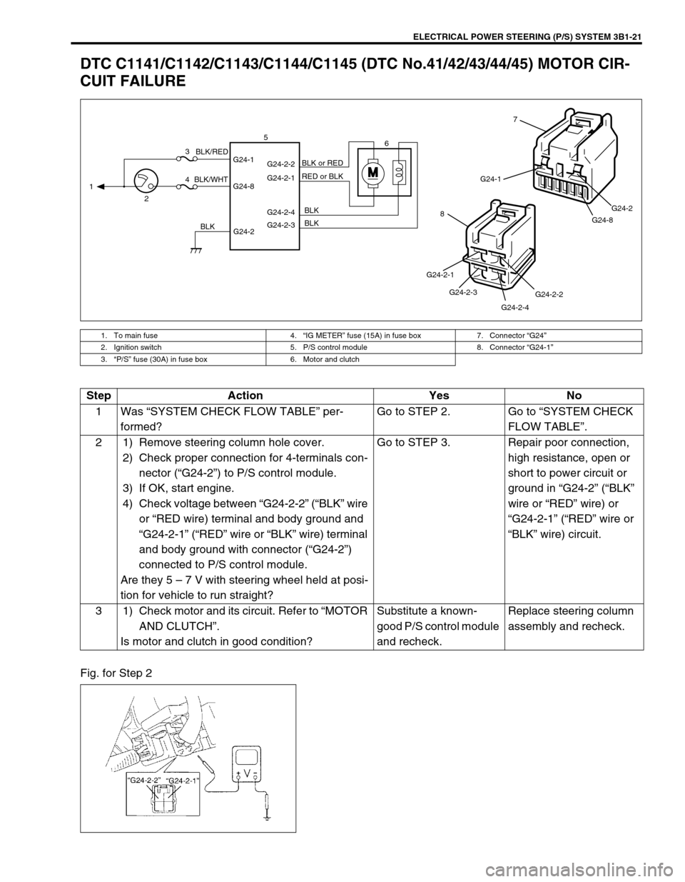
DTC C1141/C1142/C1143/C1144/C1145 (DTC No.41/42/43/44/45) MOTOR CIR-
CUIT FAILURE
Fig. for Step 2
1. To main fuse 4.“IG METER” fuse (15A) in fuse box 7. Connector “G24”
2. Ignition switch 5. P/S control module 8. Connector “G24-1”
3.“P/S” fuse (30A) in fuse box 6. Motor and clutch
MG24-1
G24-8G24-2
7
G24-2-2
G24-2-4 G24-2-3 G24-2-1
8
G24-2 G24-1
G24-8G24-2-2
G24-2-1
G24-2-4
G24-2-3 1
23
46 5
BLK/WHTBLK/RED
BLKBLK BLK RED or BLK BLK or RED
Step Action Yes No
1Was “SYSTEM CHECK FLOW TABLE” per-
formed?Go to STEP 2. Go to “SYSTEM CHECK
FLOW TABLE”.
2 1) Remove steering column hole cover.
2) Check proper connection for 4-terminals con-
nector (“G24-2”) to P/S control module.
3) If OK, start engine.
4) Check voltage between “G24-2-2” (“BLK” wire
or “RED wire) terminal and body ground and
“G24-2-1” (“RED” wire or “BLK” wire) terminal
and body ground with connector (“G24-2”)
connected to P/S control module.
Are they 5 – 7 V with steering wheel held at posi-
tion for vehicle to run straight?Go to STEP 3. Repair poor connection,
high resistance, open or
short to power circuit or
ground in “G24-2” (“BLK”
wire or “RED” wire) or
“G24-2-1” (“RED” wire or
“BLK” wire) circuit.
3 1) Check motor and its circuit. Refer to “MOTOR
AND CLUTCH”.
Is motor and clutch in good condition?Substitute a known-
good P/S control module
and recheck.Replace steering column
assembly and recheck.
Page 163 of 698
3B1-22 ELECTRICAL POWER STEERING (P/S) SYSTEM
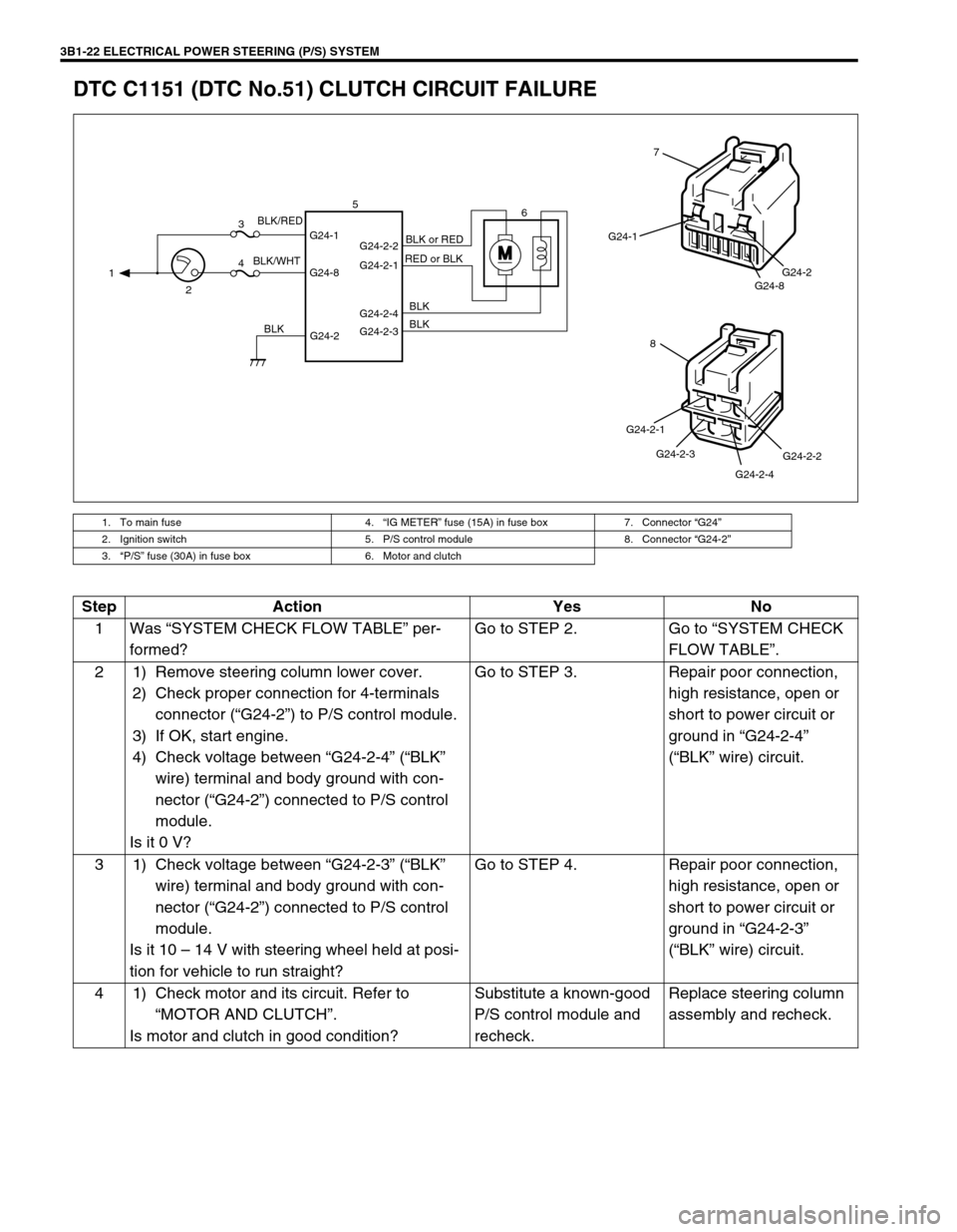
DTC C1151 (DTC No.51) CLUTCH CIRCUIT FAILURE
1. To main fuse 4.“IG METER” fuse (15A) in fuse box 7. Connector “G24”
2. Ignition switch 5. P/S control module 8. Connector “G24-2”
3.“P/S” fuse (30A) in fuse box 6. Motor and clutch
M
G24-2 G24-1
G24-8G24-2-2
G24-2-1
G24-2-4
G24-2-3 1
23
46 5
BLK/WHTBLK/RED
BLKBLK BLK RED or BLKBLK or RED
G24-1
G24-8G24-2
7
G24-2-2
G24-2-4 G24-2-3 G24-2-1
8
Step Action Yes No
1Was “SYSTEM CHECK FLOW TABLE” per-
formed?Go to STEP 2. Go to “SYSTEM CHECK
FLOW TABLE”.
2 1) Remove steering column lower cover.
2) Check proper connection for 4-terminals
connector (“G24-2”) to P/S control module.
3) If OK, start engine.
4) Check voltage between “G24-2-4” (“BLK”
wire) terminal and body ground with con-
nector (“G24-2”) connected to P/S control
module.
Is it 0 V?Go to STEP 3. Repair poor connection,
high resistance, open or
short to power circuit or
ground in “G24-2-4”
(“BLK” wire) circuit.
3 1) Check voltage between “G24-2-3” (“BLK”
wire) terminal and body ground with con-
nector (“G24-2”) connected to P/S control
module.
Is it 10 – 14 V with steering wheel held at posi-
tion for vehicle to run straight?Go to STEP 4. Repair poor connection,
high resistance, open or
short to power circuit or
ground in “G24-2-3”
(“BLK” wire) circuit.
4 1) Check motor and its circuit. Refer to
“MOTOR AND CLUTCH”.
Is motor and clutch in good condition?Substitute a known-good
P/S control module and
recheck.Replace steering column
assembly and recheck.
Page 174 of 698
STEERING WHEEL AND COLUMN 3C-1
6F1
6F2
6G
6H
6K
7A
7A1
7B1
3C1
7E
7F
8A
8B
8C
8D
8E
9
10
10A
10B
SECTION 3C
STEERING WHEEL AND COLUMN
CONTENTS
GENERAL DESCRIPTION .............................. 3C-2
STEERING COLUMN .................................. 3C-2
STEERING WHEEL AND DRIVER AIR
BAG (INFLATOR) MODULE ........................ 3C-2
DIAGNOSIS ..................................................... 3C-2
INSPECTION AND REPAIR REQUIRED
AFTER ACCIDENT ...................................... 3C-2
ON-VEHICLE SERVICE .................................. 3C-3
SERVICE PRECAUTIONS........................... 3C-3
SERVICE AND DIAGNOSIS .................... 3C-3
DISABLING AIR BAG SYSTEM ............... 3C-3
ENABLING AIR BAG SYSTEM ................ 3C-3
HANDLING AND STORAGE.................... 3C-4
DISPOSAL ............................................... 3C-4DRIVER AIR BAG (INFLATOR) MODULE .. 3C-4
STEERING WHEEL ..................................... 3C-6
CENTERING CONTACT COIL .................... 3C-7
CONTACT COIL AND COMBINATION
SWITCH ASSEMBLY .................................. 3C-8
STEERING COLUMN ASSEMBLY............ 3C-10
STEERING LOCK ASSEMBLY
(IGNITION SWITCH) ................................. 3C-16
STEERING LOWER SHAFT...................... 3C-17
CHECKING STEERING COLUMN
ASSEMBLY AND LOWER SHAFT FOR
ACCIDENT DAMAGE ................................... 3C-18
SPECIAL TOOL ............................................ 3C-19
WARNING:
For vehicles equipped with Supplemental Restraint (Air Bag) System:
Service on and around the air bag system components or wiring must be performed only by an
authorized SUZUKI dealer. Please observe all WARNINGS and “Service Precautions” under “On-
Vehicle Service” in air bag system section before performing service on or around the air bag sys-
tem components or wiring. Failure to follow WARNINGS could result in unintentional activation of
the system or could render the system inoperative. Either of these two conditions may result in
severe injury.
The procedures in this section must be followed in the order listed to temporarily disable the air
bag system and prevent false diagnostic codes from setting. Failure to follow procedures could
result in possible air bag system activation, personal injury or otherwise unneeded air bag system
repairs.
CAUTION:
When fasteners are removed, always reinstall them at the same location from which they were
removed. If a fastener needs to be replaced, use the correct part number fastener for that application.
If the correct part number fastener is not available, a fastener of equal size and strength (or stronger)
may be used. Fasteners that are not reused, and those requiring thread-locking compound, will be
called out. The correct torque value must be used when installing fasteners that require it. If the above
procedures are not followed, parts or system damage could result.
Page 180 of 698
STEERING WHEEL AND COLUMN 3C-7
INSTALLATION
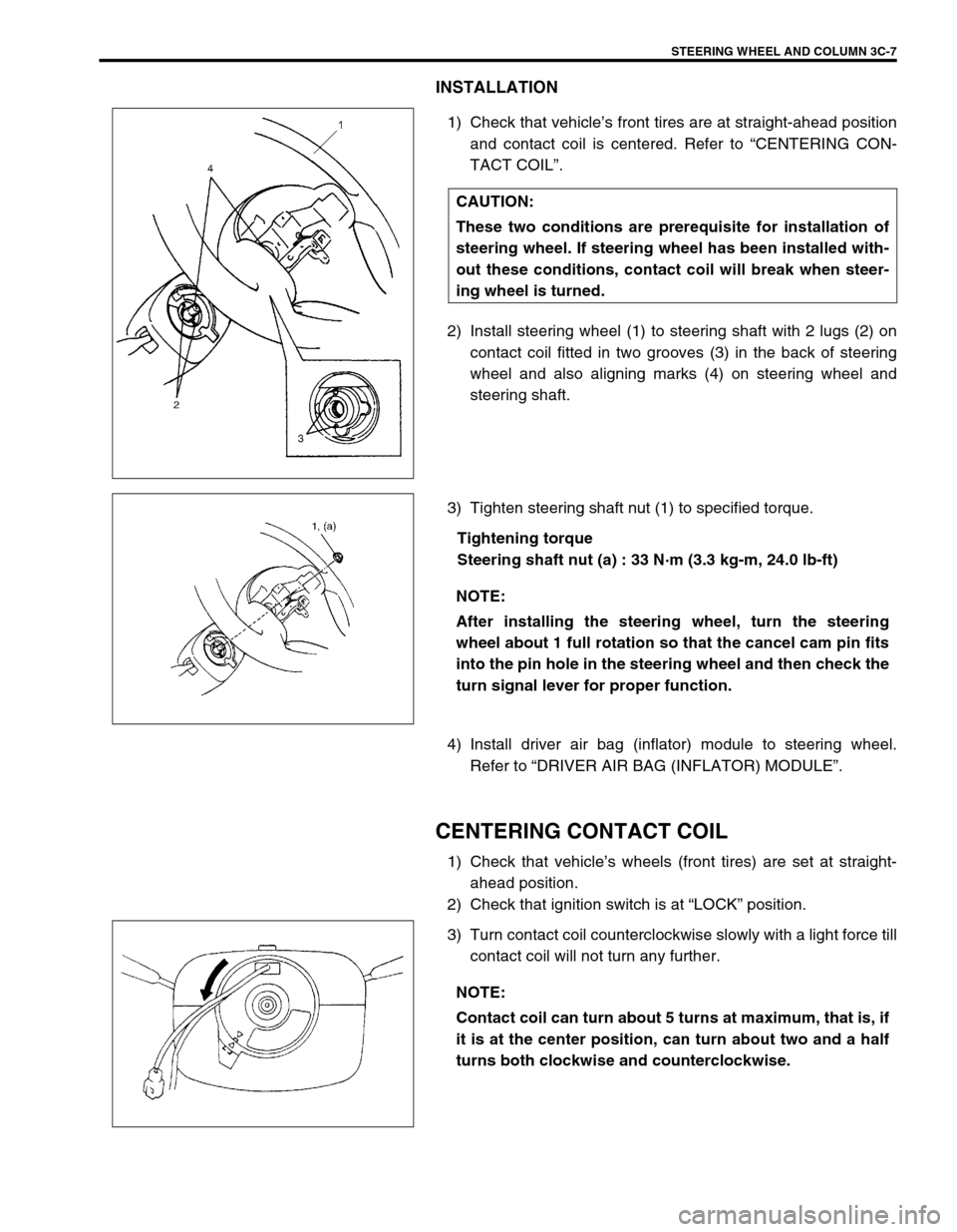
1) Check that vehicle’s front tires are at straight-ahead position
and contact coil is centered. Refer to “CENTERING CON-
TACT COIL”.
2) Install steering wheel (1) to steering shaft with 2 lugs (2) on
contact coil fitted in two grooves (3) in the back of steering
wheel and also aligning marks (4) on steering wheel and
steering shaft.
3) Tighten steering shaft nut (1) to specified torque.
Tightening torque
Steering shaft nut (a) : 33 N·m (3.3 kg-m, 24.0 lb-ft)
4) Install driver air bag (inflator) module to steering wheel.
Refer to “DRIVER AIR BAG (INFLATOR) MODULE”.
CENTERING CONTACT COIL
1) Check that vehicle’s wheels (front tires) are set at straight-
ahead position.
2) Check that ignition switch is at “LOCK” position.
3) Turn contact coil counterclockwise slowly with a light force till
contact coil will not turn any further. CAUTION:
These two conditions are prerequisite for installation of
steering wheel. If steering wheel has been installed with-
out these conditions, contact coil will break when steer-
ing wheel is turned.
NOTE:
After installing the steering wheel, turn the steering
wheel about 1 full rotation so that the cancel cam pin fits
into the pin hole in the steering wheel and then check the
turn signal lever for proper function.
NOTE:
Contact coil can turn about 5 turns at maximum, that is, if
it is at the center position, can turn about two and a half
turns both clockwise and counterclockwise.
Page 277 of 698
5-4 BRAKES
DIAGNOSIS
ROAD TESTING BRAKES
Brakes should be tested on dry, clean, smooth and reasonably level roadway which is not crowned. Road test
brakes by making brake applications with both light and heavy pedal forces at various speeds to determine if the
vehicle stops evenly and effectively. Also drive vehicle to see if it leads to one side or the other without brake
application. If it does, check the tire pressure, front end alignment and front suspension attachments for loose-
ness. See diagnosis table for other causes.
BRAKE FLUID LEAKS
Check the master cylinder fluid levels. While a slight drop in reservoir level does result from normal lining wear,
an abnormally low level indicates a leak in the system. In such a case, check the entire brake system for leak-
age. If even a slight evidence of leakage is noted, the cause should be corrected or defective parts should be
replaced.
SUBSTANDARD OR CONTAMINATED BRAKE FLUID
Improper brake fluid, mineral oil or water in the fluid may cause the brake fluid to boil or the rubber components
in the hydraulic system to deteriorate.
If primary piston cups are swollen, then rubber parts have deteriorated. This deterioration may also be evi-
denced by swollen wheel cylinder piston cups on the drum brake wheels.
If deterioration of rubber is evident, disassemble all hydraulic parts and wash with alcohol. Dry these parts with
compressed air before assembly to keep alcohol out of the system. Replace all rubber parts in the system,
including hoses. Also, when working on the brake mechanisms, check for fluid on the linings.
If excessive fluid is found, replace the pads.
If master cylinder piston seals are satisfactory, check for leakage or excessive heat conditions. If leakage is not
found, drain fluid, flush with brake fluid, refill and bleed system.
The system must be flushed if there is any doubt as to the grade of fluid in the system or if fluid has been used
which contained parts that have been subjected to contaminated fluid.
Page 278 of 698
BRAKES 5-5
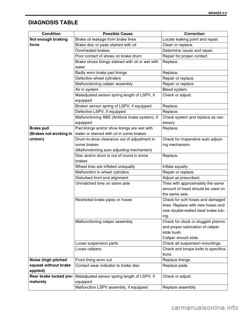
DIAGNOSIS TABLE
Condition Possible Cause Correction
Not enough braking
forceBrake oil leakage from brake lines Locate leaking point and repair.
Brake disc or pads stained with oil Clean or replace.
Overheated brakes Determine cause and repair.
Poor contact of shoes on brake drum Repair for proper contact.
Brake shoes linings stained with oil or wet with
waterReplace.
Badly worn brake pad linings Replace.
Defective wheel cylinders Repair or replace.
Malfunctioning caliper assembly Repair or replace.
Air in system Bleed system.
Maladjusted sensor spring length of LSPV, if
equippedCheck or adjust.
Broken sensor spring of LSPV, if equipped Replace.
Defective LSPV, if equipped Replace.
Malfunctioning ABS (Antilock brake system), if
equippedCheck system and replace as nec-
essary.
Brake pull
(Brakes not working in
unison)Pad linings and/or shoe linings are wet with
water or stained with oil in some brakesReplace.
Drum-to-shoe clearance out of adjustment in
some brakes
(Malfunctioning auto adjusting mechanism)Check for inoperative auto adjust-
ing mechanism.
Disc and/or drum is out of round in some
brakesReplace.
Wheel tires are inflated unequally Inflate equally.
Malfunction in wheel cylinders Repair or replace.
Disturbed front end alignment Adjust as prescribed.
Unmatched tires on same axle Tires with approximately the same
amount of tread should be used on
the same axle.
Restricted brake pipes or hoses Check for soft hoses and damaged
lines. Replace with new hoses and
new double-walled steel brake tub-
ing.
Malfunctioning caliper assembly Check for stuck or sluggish pistons
and proper lubrication of caliper
slide bush.
Caliper should slide.
Loose suspension parts Check all suspension mountings.
Loose calipers Check and torque bolts to specifica-
tions.
Noise (high pitched
squeak without brake
applied)Front lining worn out Replace linings.
Contact wear indicator to brake disc Replace pads.
Rear brake locked pre-
maturelyMaladjusted sensor spring length of LSPV, if
equippedCheck or adjust.
Malfunction LSPV assembly, if equipped Replace assembly.
Page 279 of 698
5-6 BRAKES
Excessive pedal travel
(Pedal stroke too
large)Partial brake system failure Check brake systems and repair as
necessary.
Insufficient fluid in master cylinder reservoirs Fill reservoirs with approved brake
fluid.
Check for leaks and air in brake
system.
Check warning light. Bleed system
if required.
Air in system (soft/spongy pedal) Bleed system.
Rear brake system not adjusted
(malfunctioning auto adjusting mechanism)Repair auto adjusting mechanism.
Adjust rear brakes.
Bent brake shoes Replace brake shoes.
Worn rear brake shoes Replace brake shoes.
Brake locked
(For vehicle equipped
with ABS)Malfunctioning ABS Check system referring to Section
5E1.
Dragging brakes
(A very light drag is
present in all brakes
immediately after
pedal is released)Master cylinder pistons not returning correctly Replace master cylinder.
Restricted brake pipes or hoses Check for soft hoses or damaged
pipes and replace with new hoses
and/or new double-walled steel
brake piping.
Incorrect parking brake adjustment on rear
brakesCheck and adjust to correct specifi-
cations.
Weakened or broken return springs in the brake Replace.
Sluggish parking brake cables or linkage Repair or replace.
Wheel cylinder or caliper piston sticking Repair as necessary.
Badly worn piston seal in caliper Replace piston seal.
Pedal pulsation
(Pedal pulsates when
depressed for brak-
ing)Damaged or loose wheel bearings Replace wheel bearings.
Distorted steering knuckle or rear wheel spindle Replace knuckle or rear wheel spin-
dle.
Excessive disc lateral runout Check per instructions. If not within
specifications, replace or machine
disc.
Parallelism between pad and disc not within
specificationsCheck per instructions. If not within
specifications, replace or machine
disc.
Rear drums out of round Check runout.
Repair or replace drum as neces-
sary.
Braking noise
Glazed shoe linings, or foreign matters stuck to
liningsRepair or replace shoe linings.
Worn or distorted shoe linings Replace shoe lining (or pad).
Loose front wheel bearings Replace wheel bearing.
Distorted backing plates or loose mounting
boltsReplace or retighten securing bolts.
Contact wear indicator to brake disc Replace pads. Condition Possible Cause Correction
Page 280 of 698
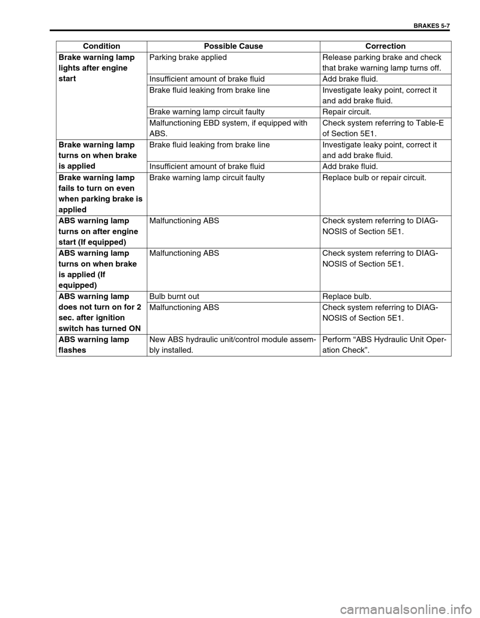
BRAKES 5-7
Brake warning lamp
lights after engine
startParking brake applied Release parking brake and check
that brake warning lamp turns off.
Insufficient amount of brake fluid Add brake fluid.
Brake fluid leaking from brake line Investigate leaky point, correct it
and add brake fluid.
Brake warning lamp circuit faulty Repair circuit.
Malfunctioning EBD system, if equipped with
ABS.Check system referring to Table-E
of Section 5E1.
Brake warning lamp
turns on when brake
is appliedBrake fluid leaking from brake line Investigate leaky point, correct it
and add brake fluid.
Insufficient amount of brake fluid Add brake fluid.
Brake warning lamp
fails to turn on even
when parking brake is
appliedBrake warning lamp circuit faulty Replace bulb or repair circuit.
ABS warning lamp
turns on after engine
start (If equipped)Malfunctioning ABS Check system referring to DIAG-
NOSIS of Section 5E1.
ABS warning lamp
turns on when brake
is applied (If
equipped)Malfunctioning ABS Check system referring to DIAG-
NOSIS of Section 5E1.
ABS warning lamp
does not turn on for 2
sec. after ignition
switch has turned ONBulb burnt out Replace bulb.
Malfunctioning ABS Check system referring to DIAG-
NOSIS of Section 5E1.
ABS warning lamp
flashesNew ABS hydraulic unit/control module assem-
bly installed.Perform “ABS Hydraulic Unit Oper-
ation Check”. Condition Possible Cause Correction
Page 283 of 698
5-10 BRAKES
PARKING BRAKE INSPECTION AND
ADJUSTMENT
INSPECTION
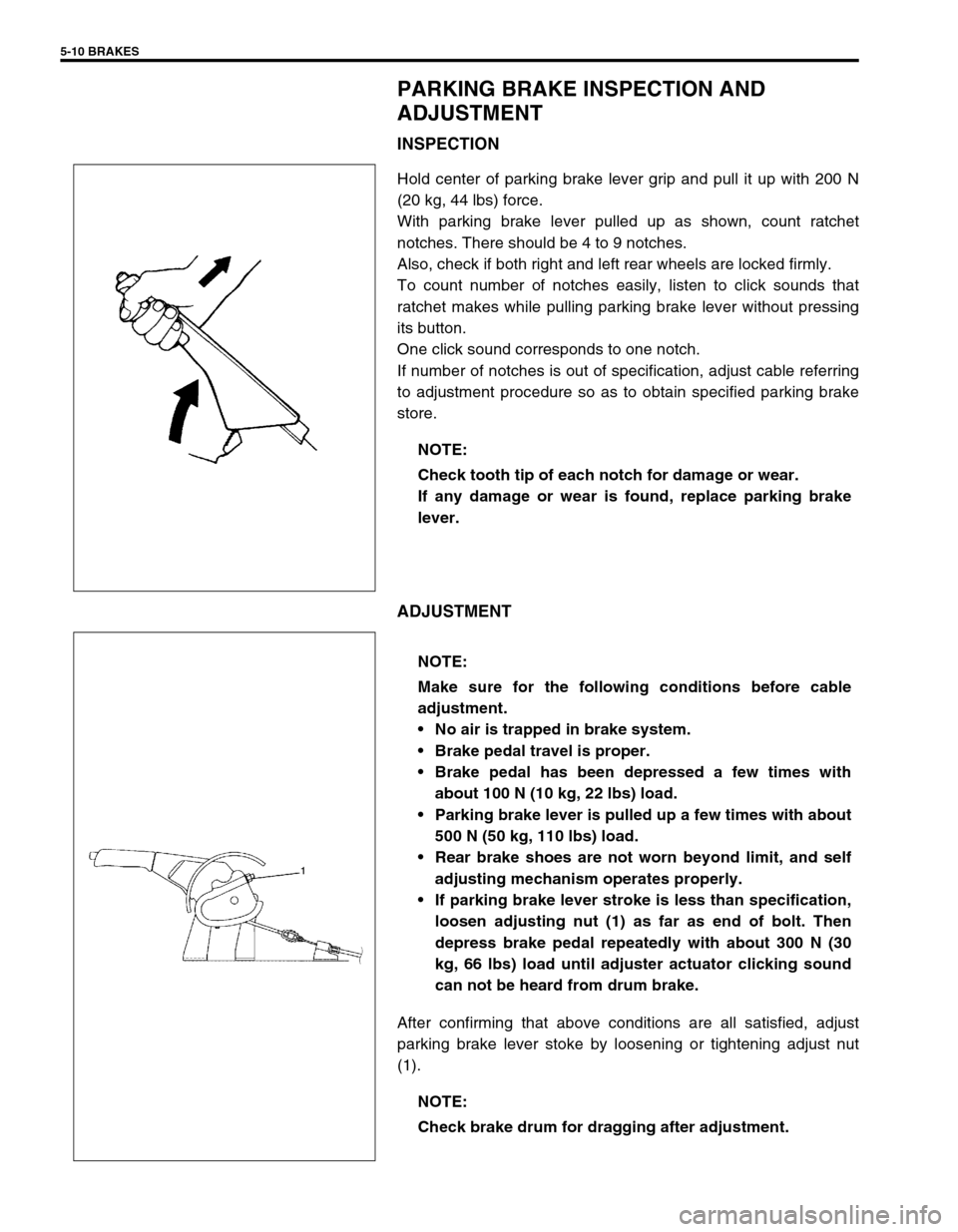
Hold center of parking brake lever grip and pull it up with 200 N
(20 kg, 44 lbs) force.
With parking brake lever pulled up as shown, count ratchet
notches. There should be 4 to 9 notches.
Also, check if both right and left rear wheels are locked firmly.
To count number of notches easily, listen to click sounds that
ratchet makes while pulling parking brake lever without pressing
its button.
One click sound corresponds to one notch.
If number of notches is out of specification, adjust cable referring
to adjustment procedure so as to obtain specified parking brake
store.
ADJUSTMENT
After confirming that above conditions are all satisfied, adjust
parking brake lever stoke by loosening or tightening adjust nut
(1).NOTE:
Check tooth tip of each notch for damage or wear.
If any damage or wear is found, replace parking brake
lever.
NOTE:
Make sure for the following conditions before cable
adjustment.
No air is trapped in brake system.
Brake pedal travel is proper.
Brake pedal has been depressed a few times with
about 100 N (10 kg, 22 lbs) load.
Parking brake lever is pulled up a few times with about
500 N (50 kg, 110 lbs) load.
Rear brake shoes are not worn beyond limit, and self
adjusting mechanism operates properly.
If parking brake lever stroke is less than specification,
loosen adjusting nut (1) as far as end of bolt. Then
depress brake pedal repeatedly with about 300 N (30
kg, 66 lbs) load until adjuster actuator clicking sound
can not be heard from drum brake.
NOTE:
Check brake drum for dragging after adjustment.