ECO mode SUZUKI SWIFT 2000 1.G RG413 Service Workshop Manual
[x] Cancel search | Manufacturer: SUZUKI, Model Year: 2000, Model line: SWIFT, Model: SUZUKI SWIFT 2000 1.GPages: 698, PDF Size: 16.01 MB
Page 2 of 698
FOREWORD
This manual contains procedures for diagnosis, maintenance, adjustments, minor service operations, replace-
ment of components (Service) and for disassembly and assembly of major components (Unit Repair-Overhaul).
Applicable model: RG413
The contents are classified into sections each of which is given a section number as indicated in the Table of
Contents on following page. And on the first page of each individual section is an index of that section.
This manual should be kept in a handy place for ready reference of the service work.
Strict observance of the so specified items will enable one to obtain the full performance of the vehicle.
When replacing parts or servicing by disassembling, it is recommended to use SUZUKI genuine parts, tools and
service materials (lubricant, sealants, etc.) as specified in each description.
All information, illustrations and specifications contained in this literature are based on the latest product infor-
mation available at the time of publication approval. And used as the main subject of description is the vehicle of
standard specifications among others.
Therefore, note that illustrations may differ from the vehicle being actually serviced.
The right is reserved to make changes at any time without notice.
Related Manual
© COPYRIGHT SUZUKI MOTOR CORPORATION 2000Manual Name Manual No.
RG413 Wiring Diagram Manual 99512-80G00-015
Page 50 of 698
MAINTENANCE AND LUBRICATION 0B-21
STEERING
Check to ensure that steering wheel is free from instability, or abnormally heavy feeling.
Check that the vehicle does not wander or pull to one side.
ENGINE
Check that engine responds readily at all speeds.
Check that engine is free from abnormal noise and abnormal vibration.
BODY, WHEELS AND POWER TRANSMITTING SYSTEM
Check that body, wheels and power transmitting system are free from abnormal noise and abnormal vibration or
any other abnormal condition.
METERS AND GAUGE
Check that speedometer, odometer, fuel meter, temperature gauge, etc. are operating accurately.
LIGHTS
Check that all lights operate properly.
WINDSHIELD DEFROSTER
Periodically check that air comes out from defroster outlet when operating heater or air conditioning.
Set mode control lever to defroster position and fan switch lever to “HI” position for this check.
RECOMMENDED FLUIDS AND LUBRICANTS
Engine oil SE, SF, SG, SH or SJ grade (Refer to “ENGINE OIL AND OIL FILTER”
in this section for engine oil viscosity.)
Engine coolant
(Ethylene glycol base coolant)“Antifreeze/Anticorrosion coolant”
Brake fluid DOT 3
Manual transmission oil Refer to “M/T OIL CHANGE” in Section 7A.
Transfer oil (4WD) Refer to “TRANSFER OIL CHANGE” in Section 7D.
Differential oil (4WD) Refer to “DIFFERENTIAL OIL CHANGE” in Section 7F.
Automatic transmission fluid
An equivalent of DEXRON
®-III
Door hinges Engine oil or water resistance chassis grease
Hood latch assembly Engine oil or water resistance chassis grease
Key lock cylinder Spray lubricant
Page 248 of 698
WHEELS AND TIRES 3F-3
HOW TO MEASURE WHEEL RUNOUT
To measure the wheel runout, it is necessary to use an accurate
dial indicator. The tire may be on or off the wheel. The wheel
should be installed to the wheel balancer of the like for proper
measurement.
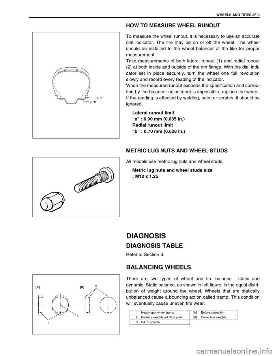
Take measurements of both lateral runout (1) and radial runout
(2) at both inside and outside of the rim flange. With the dial indi-
cator set in place securely, turn the wheel one full revolution
slowly and record every reading of the indicator.
When the measured runout exceeds the specification and correc-
tion by the balancer adjustment is impossible, replace the wheel.
If the reading is affected by welding, paint or scratch, it should be
ignored.
Lateral runout limit
“a” : 0.90 mm (0.035 in.)
Radial runout limit
“b” : 0.70 mm (0.028 in.)
METRIC LUG NUTS AND WHEEL STUDS
All models use metric lug nuts and wheel studs.
Metric lug nuts and wheel studs size
: M12 x 1.25
DIAGNOSIS
DIAGNOSIS TABLE
Refer to Section 3.
BALANCING WHEELS
There are two types of wheel and tire balance : static and
dynamic. Static balance, as shown in left figure, is the equal distri-
bution of weight around the wheel. Wheels that are statically
unbalanced cause a bouncing action called tramp. This condition
will eventually cause uneven tire wear.
1. Heavy spot wheel tramp [A] : Before correction
2. Balance weights addition point [B] : Corrective weights
3. C/L of spindle
Page 251 of 698
3F-6 WHEELS AND TIRES
INFLATION OF TIRES
The pressure recommended for any model is carefully calculated to give a satisfactory ride, stability, steering,
tread wear, tire life and resistance to bruises.
Tire pressure, with tires cold, (after vehicle has set for 3 hours or more, or driven less than one mile) should be
checked monthly or before any extended trip. Set to the specifications on the “Tire Placard” located on the left
door (right door for right-hand side steering vehicle) lock pillar.
It is normal for tire pressure to increase when the tires become hot during driving.
Do not bleed or reduce tire pressure after driving. Bleeding reduces the “Cold Inflation Pressure”.
Higher than recommended pressure can cause :
Hard ride
Tire bruising or carcass damage
Rapid tread wear at center of tire
Unequal pressure on same axle can cause :
Uneven braking
Steering lead
Reduced handling
Swerve on acceleration
Lower than recommended pressure can cause :
Tire squeal on turns
Hard Steering
Rapid and uneven wear on the edges of the tread
Tire rim bruises and rupture
Tire cord breakage
High tire temperature
Reduced handling
High fuel consumption
TIRE ROTATION
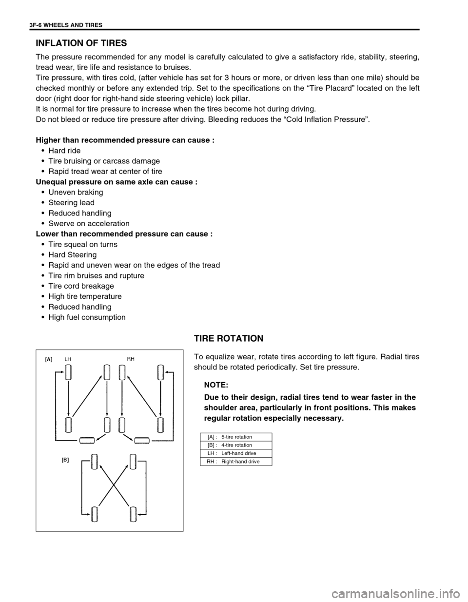
To equalize wear, rotate tires according to left figure. Radial tires
should be rotated periodically. Set tire pressure.
NOTE:
Due to their design, radial tires tend to wear faster in the
shoulder area, particularly in front positions. This makes
regular rotation especially necessary.
[A] : 5-tire rotation
[B] : 4-tire rotation
LH : Left-hand drive
RH : Right-hand drive
Page 375 of 698
6-6 ENGINE GENERAL INFORMATION AND DIAGNOSIS
FUEL PRESSURE RELIEF PROCEDURE
After making sure that engine is cold, release fuel pressure as fol-
lows.
1) Place transmission gear shift lever in “Neutral” (Shift selector
lever to “P” range for A/T model), set parking brake, and
block drive wheels.
2) Remove relay box cover.
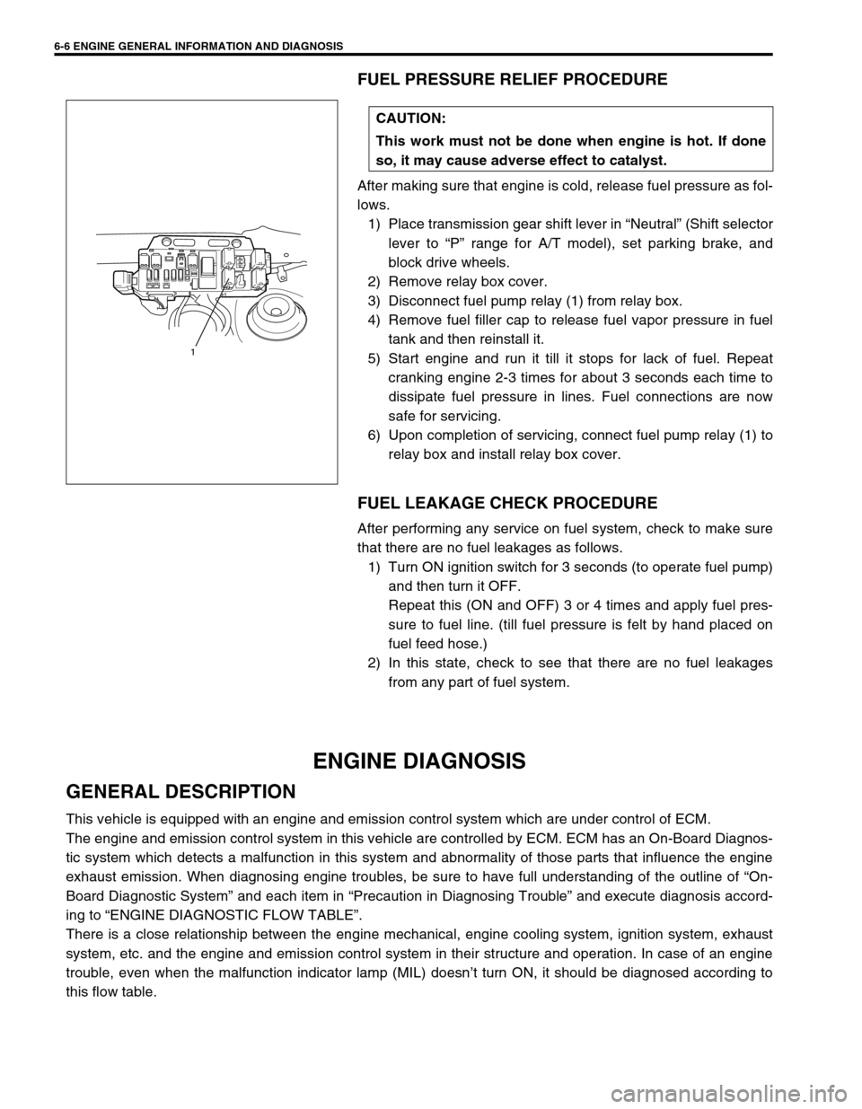
3) Disconnect fuel pump relay (1) from relay box.
4) Remove fuel filler cap to release fuel vapor pressure in fuel
tank and then reinstall it.
5) Start engine and run it till it stops for lack of fuel. Repeat
cranking engine 2-3 times for about 3 seconds each time to
dissipate fuel pressure in lines. Fuel connections are now
safe for servicing.
6) Upon completion of servicing, connect fuel pump relay (1) to
relay box and install relay box cover.
FUEL LEAKAGE CHECK PROCEDURE
After performing any service on fuel system, check to make sure
that there are no fuel leakages as follows.
1) Turn ON ignition switch for 3 seconds (to operate fuel pump)
and then turn it OFF.
Repeat this (ON and OFF) 3 or 4 times and apply fuel pres-
sure to fuel line. (till fuel pressure is felt by hand placed on
fuel feed hose.)
2) In this state, check to see that there are no fuel leakages
from any part of fuel system.
ENGINE DIAGNOSIS
GENERAL DESCRIPTION
This vehicle is equipped with an engine and emission control system which are under control of ECM.
The engine and emission control system in this vehicle are controlled by ECM. ECM has an On-Board Diagnos-
tic system which detects a malfunction in this system and abnormality of those parts that influence the engine
exhaust emission. When diagnosing engine troubles, be sure to have full understanding of the outline of “On-
Board Diagnostic System” and each item in “Precaution in Diagnosing Trouble” and execute diagnosis accord-
ing to “ENGINE DIAGNOSTIC FLOW TABLE”.
There is a close relationship between the engine mechanical, engine cooling system, ignition system, exhaust
system, etc. and the engine and emission control system in their structure and operation. In case of an engine
trouble, even when the malfunction indicator lamp (MIL) doesn’t turn ON, it should be diagnosed according to
this flow table.CAUTION:
This work must not be done when engine is hot. If done
so, it may cause adverse effect to catalyst.
1
Page 376 of 698
ENGINE GENERAL INFORMATION AND DIAGNOSIS 6-7
ON-BOARD DIAGNOSTIC SYSTEM (VEHICLE
WITH IMMOBILIZER INDICATOR LAMP)
ECM in this vehicle has following functions.
When the ignition switch is turned ON with the engine at a
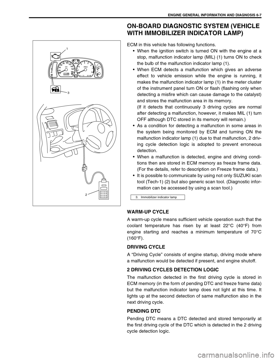
stop, malfunction indicator lamp (MIL) (1) turns ON to check
the bulb of the malfunction indicator lamp (1).
When ECM detects a malfunction which gives an adverse
effect to vehicle emission while the engine is running, it
makes the malfunction indicator lamp (1) in the meter cluster
of the instrument panel turn ON or flash (flashing only when
detecting a misfire which can cause damage to the catalyst)
and stores the malfunction area in its memory.
(If it detects that continuously 3 driving cycles are normal
after detecting a malfunction, however, it makes MIL (1) turn
OFF although DTC stored in its memory will remain.)
As a condition for detecting a malfunction in some areas in
the system being monitored by ECM and turning ON the
malfunction indicator lamp (1) due to that malfunction, 2 driv-
ing cycle detection logic is adopted to prevent erroneous
detection.
When a malfunction is detected, engine and driving condi-
tions then are stored in ECM memory as freeze frame data.
(For the details, refer to description on Freeze frame data.)
It is possible to communicate by using not only SUZUKI scan
tool (Tech-1) (2) but also generic scan tool. (Diagnostic infor-
mation can be accessed by using a scan tool.)
WARM-UP CYCLE
A warm-up cycle means sufficient vehicle operation such that the
coolant temperature has risen by at least 22°C (40°F) from
engine starting and reaches a minimum temperature of 70°C
(160°F).
DRIVING CYCLE
A “Driving Cycle” consists of engine startup, driving mode where
a malfunction would be detected if present, and engine shutoff.
2 DRIVING CYCLES DETECTION LOGIC
The malfunction detected in the first driving cycle is stored in
ECM memory (in the form of pending DTC and freeze frame data)
but the malfunction indicator lamp does not light at this time. It
lights up at the second detection of same malfunction also in the
next driving cycle.
PENDING DTC
Pending DTC means a DTC detected and stored temporarily at
the first driving cycle of the DTC which is detected in the 2 driving
cycle detection logic.
3. Immobilizer indicator lamp
ODO TRIP AB
3 1
2
Page 392 of 698

ENGINE GENERAL INFORMATION AND DIAGNOSIS 6-23
ENGINE BASIC INSPECTION
This check is very important for troubleshooting when ECM has detected no DTC and no abnormality has been
found in visual inspection.
Follow the flow table carefully.
Step Action Yes No
1Was “ENGINE DIAG. FLOW TABLE” per-
formed?Go to Step 2. Go to “ENGINE DIAG.
FLOW TABLE”.
2 Check battery voltage.
Is it 11 V or more?Go to Step 3. Charge or replace battery.
3 Is engine cranked? Go to Step 4. Go to “DIAGNOSIS” in
Section 6G.
4 Does engine start? Go to Step 5. Go to Step 7.
5 Check idle speed as follows :
1) Warm up engine to normal operating temp.
2) Shift transmission to neutral position for M/T
(“P” position for A/T).
3) All of electrical loads are switched off.
4) Check engine idle speed with scan tool.
See Fig. 1.
Is it 650 – 750 r/min (700 – 800 r/min. for A/T
vehicle)?Go to Step 6. Go to “ENGINE DIAGNO-
SIS TABLE”.
6 Check ignition timing as follows :
1) When SUZUKI scan tool is not available,
disconnect scan tool from DLC and connect
test switch terminal of monitor connector to
ground. See Fig. 2.
When using SUZUKI scan tool, select
“MISC” mode on SUZUKI scan tool and fix
ignition timing to initial one. See Fig. 3.
2) Using timing light (1), check initial ignition
timing. See Fig. 4.
Is it 5° ± 3° BTDC at specified idle speed?Go to “ENGINE DIAGNO-
SIS TABLE”.Check ignition control
related parts referring to
Section 6F1.
7 Is immobilizer control system equipped? Go to Step 8. Go to Step 9.
8 Check immobilizer system malfunction as fol-
lows.
1) Check immobilizer indicator lamp or MIL
(malfunction indicator lamp) for flashing.
Is it flashing when ignition switch is turned to
ON position?Go to “DIAGNOSIS” in
Section 8G.Go to Step 9.
9 Check fuel supply as follows :
1) Check to make sure that enough fuel is
filled in fuel tank.
2) Turn ON ignition switch for 2 seconds and
then OFF. See Fig. 5.
Is fuel pressure felt from fuel feed hose (1)
when ignition switch is turned ON?Go to Step 11. Go to Step 10.
10 Check fuel pump for operating.
Was fuel pump operating sound heard from fuel
filler for about 10 seconds after ignition switch
ON and stop?Go to “DIAG. FLOW
TABLE B-3”.Go to “DIAG. FLOW
TABLE B-2”.
Page 409 of 698
6-40 ENGINE GENERAL INFORMATION AND DIAGNOSIS
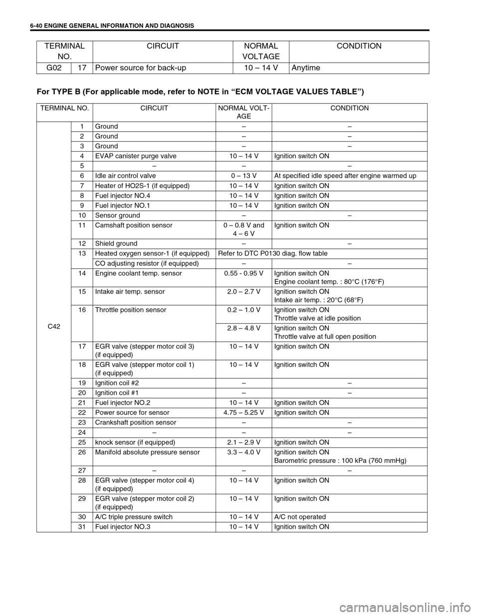
For TYPE B (For applicable mode, refer to NOTE in “ECM VOLTAGE VALUES TABLE”) G02 17 Power source for back-up 10 – 14 V Anytime
TERMINAL NO. CIRCUIT NORMAL VOLT-
AGECONDITION
C421Ground––
2Ground––
3Ground––
4 EVAP canister purge valve 10 – 14 V Ignition switch ON
5–– –
6 Idle air control valve 0 – 13 V At specified idle speed after engine warmed up
7 Heater of HO2S-1 (if equipped) 10 – 14 V Ignition switch ON
8 Fuel injector NO.4 10 – 14 V Ignition switch ON
9 Fuel injector NO.1 10 – 14 V Ignition switch ON
10 Sensor ground––
11 Camshaft position sensor 0 – 0.8 V and
4 – 6 VIgnition switch ON
12 Shield ground––
13 Heated oxygen sensor-1 (if equipped) Refer to DTC P0130 diag. flow table
CO adjusting resistor (if equipped)––
14 Engine coolant temp. sensor 0.55 - 0.95 V Ignition switch ON
Engine coolant temp. : 80°C (176°F)
15 Intake air temp. sensor 2.0 – 2.7 V Ignition switch ON
Intake air temp. : 20°C (68°F)
16 Throttle position sensor 0.2 – 1.0 V Ignition switch ON
Throttle valve at idle position
2.8 – 4.8 V Ignition switch ON
Throttle valve at full open position
17 EGR valve (stepper motor coil 3)
(if equipped)10 – 14 V Ignition switch ON
18 EGR valve (stepper motor coil 1)
(if equipped)10 – 14 V Ignition switch ON
19 Ignition coil #2––
20 Ignition coil #1––
21 Fuel injector NO.2 10 – 14 V Ignition switch ON
22 Power source for sensor 4.75 – 5.25 V Ignition switch ON
23 Crankshaft position sensor––
24–– –
25 knock sensor (if equipped) 2.1 – 2.9 V Ignition switch ON
26 Manifold absolute pressure sensor 3.3 – 4.0 V Ignition switch ON
Barometric pressure : 100 kPa (760 mmHg)
27–– –
28 EGR valve (stepper motor coil 4)
(if equipped)10 – 14 V Ignition switch ON
29 EGR valve (stepper motor coil 2)
(if equipped)10 – 14 V Ignition switch ON
30 A/C triple pressure switch 10 – 14 V A/C not operated
31 Fuel injector NO.3 10 – 14 V Ignition switch ON
TERMINAL
NO.CIRCUIT NORMAL
VOLTAGECONDITION
Page 451 of 698
6-82 ENGINE GENERAL INFORMATION AND DIAGNOSIS
DTC CONFIRMATION PROCEDURE
1) Turn ignition switch OFF.
2) Clear DTC with ignition switch ON.
3) Check vehicle and environmental condition for :
–Altitude (barometric pressure) : 2400 m, 8000 ft or less (560 mmHg, 75 kPa or more)
–Ambient temp. : –10°C, 14°F or higher
–Intake air temp. : 70°C, 158°F or lower
–Engine coolant temp. : – 10 – 110°C, 14 – 230°F
4) Start engine and keep it at idle for 2 min. or more.
5) Check DTC in “DTC” mode and pending DTC in “ON BOARD TEST” or “PENDING DTC” mode.
6) If DTC is not detected at idle, consult usual driving based on information obtained in “Customer complaint
analysis” and “Freeze frame data check”.
INSPECTION
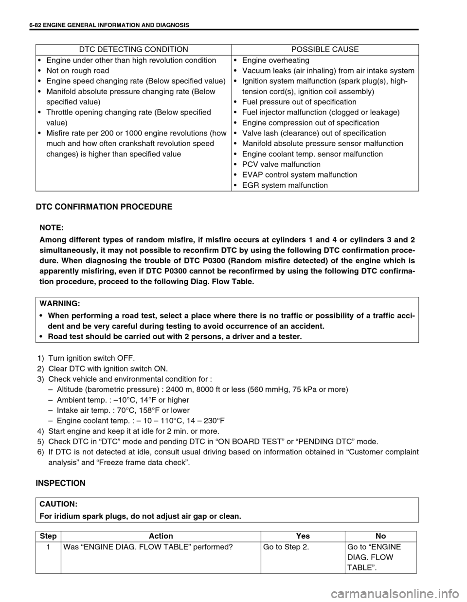
DTC DETECTING CONDITION POSSIBLE CAUSE
Engine under other than high revolution condition
Not on rough road
Engine speed changing rate (Below specified value)
Manifold absolute pressure changing rate (Below
specified value)
Throttle opening changing rate (Below specified
value)
Misfire rate per 200 or 1000 engine revolutions (how
much and how often crankshaft revolution speed
changes) is higher than specified valueEngine overheating
Vacuum leaks (air inhaling) from air intake system
Ignition system malfunction (spark plug(s), high-
tension cord(s), ignition coil assembly)
Fuel pressure out of specification
Fuel injector malfunction (clogged or leakage)
Engine compression out of specification
Valve lash (clearance) out of specification
Manifold absolute pressure sensor malfunction
Engine coolant temp. sensor malfunction
PCV valve malfunction
EVAP control system malfunction
EGR system malfunction
NOTE:
Among different types of random misfire, if misfire occurs at cylinders 1 and 4 or cylinders 3 and 2
simultaneously, it may not possible to reconfirm DTC by using the following DTC confirmation proce-
dure. When diagnosing the trouble of DTC P0300 (Random misfire detected) of the engine which is
apparently misfiring, even if DTC P0300 cannot be reconfirmed by using the following DTC confirma-
tion procedure, proceed to the following Diag. Flow Table.
WARNING:
When performing a road test, select a place where there is no traffic or possibility of a traffic acci-
dent and be very careful during testing to avoid occurrence of an accident.
Road test should be carried out with 2 persons, a driver and a tester.
CAUTION:
For iridium spark plugs, do not adjust air gap or clean.
Step Action Yes No
1Was “ENGINE DIAG. FLOW TABLE” performed? Go to Step 2. Go to “ENGINE
DIAG. FLOW
TABLE”.
Page 457 of 698
6-88 ENGINE GENERAL INFORMATION AND DIAGNOSIS
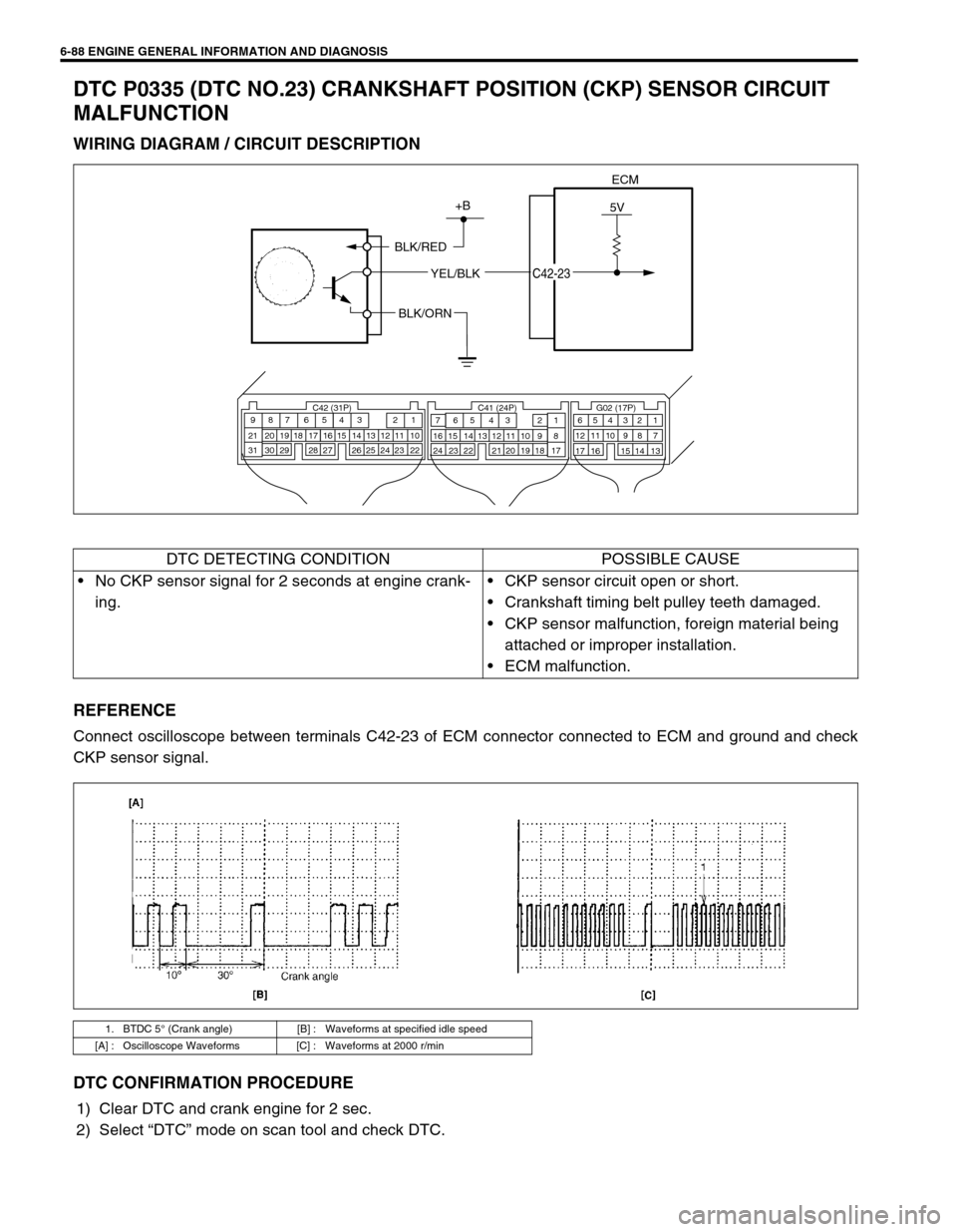
DTC P0335 (DTC NO.23) CRANKSHAFT POSITION (CKP) SENSOR CIRCUIT
MALFUNCTION
WIRING DIAGRAM / CIRCUIT DESCRIPTION
REFERENCE
Connect oscilloscope between terminals C42-23 of ECM connector connected to ECM and ground and check
CKP sensor signal.
DTC CONFIRMATION PROCEDURE
1) Clear DTC and crank engine for 2 sec.
2) Select “DTC” mode on scan tool and check DTC.
ECM
5V+B
BLK/RED
YEL/BLK
C42-23
BLK/ORN
C42 (31P) C41 (24P) G02 (17P)1 2 3 4 5 6 7 8 9
10 11 12 13 14 15 16 17 18 19 20 21
22 23 24 25 26 28 27 29 30 315 6
1 2 3 4 5 6 7
11 12
9 10 11 13 12 14 15 16
16 171 2
7 8
13 14 3 4
9 10
15 17 188
19 20 21 22 23 24
DTC DETECTING CONDITION POSSIBLE CAUSE
No CKP sensor signal for 2 seconds at engine crank-
ing.CKP sensor circuit open or short.
Crankshaft timing belt pulley teeth damaged.
CKP sensor malfunction, foreign material being
attached or improper installation.
ECM malfunction.
1. BTDC 5° (Crank angle) [B] : Waveforms at specified idle speed
[A] : Oscilloscope Waveforms [C] : Waveforms at 2000 r/min