gas type SUZUKI SWIFT 2000 1.G RG413 Service Workshop Manual
[x] Cancel search | Manufacturer: SUZUKI, Model Year: 2000, Model line: SWIFT, Model: SUZUKI SWIFT 2000 1.GPages: 698, PDF Size: 16.01 MB
Page 91 of 698
1B-26 AIR CONDITIONING (OPTIONAL)
REMOVING MANIFOLD GAUGE SET
When A/C system has been charged with a specified amount of refrigerant, remove manifold gauge set as fol-
lows :
1) Close low pressure side valve of manifold gauge set. (The high pressure side valve is closed continuously
during the process of charging.)
2) Close refrigerant container valve.
3) Stop engine.
4) Using shop rag, remove charging hoses from service valves. This operation must be performed rapidly.
5) Put caps on service valves.
LEAK TEST
Whenever a refrigerant leak is suspected in the system or any
service operation has been performed which may result in dis-
turbing lines or connections, it is advisable to test for leaks.
Common sense should be used in performing any refrigerant leak
test, since the need and extent of any such test will, in general,
depend upon the nature of a complaint and the type of a service
performed on the system.
LIQUID LEAK DETECTORS
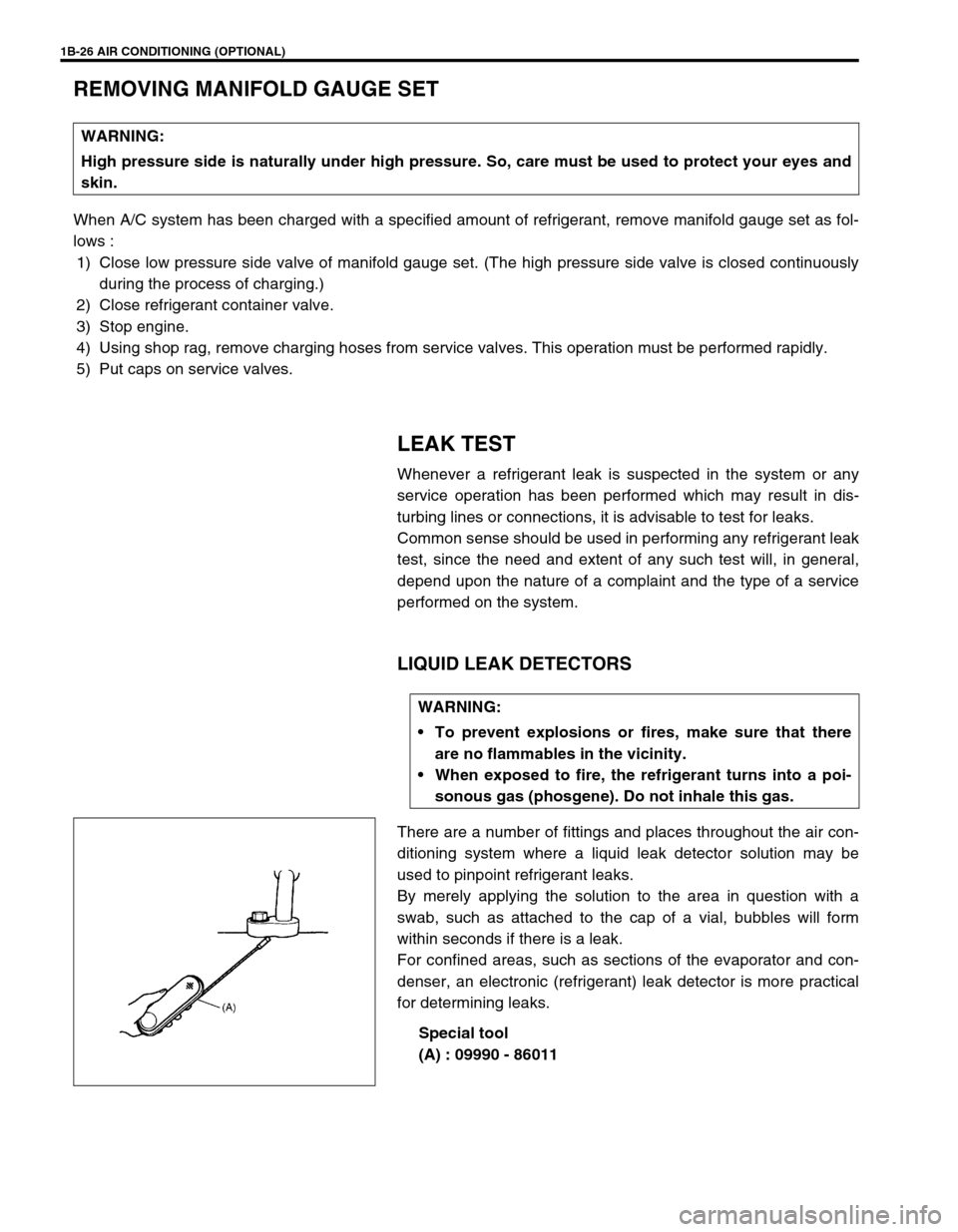
There are a number of fittings and places throughout the air con-
ditioning system where a liquid leak detector solution may be
used to pinpoint refrigerant leaks.
By merely applying the solution to the area in question with a
swab, such as attached to the cap of a vial, bubbles will form
within seconds if there is a leak.
For confined areas, such as sections of the evaporator and con-
denser, an electronic (refrigerant) leak detector is more practical
for determining leaks.
Special tool
(A) : 09990 - 86011 WARNING:
High pressure side is naturally under high pressure. So, care must be used to protect your eyes and
skin.
WARNING:
To prevent explosions or fires, make sure that there
are no flammables in the vicinity.
When exposed to fire, the refrigerant turns into a poi-
sonous gas (phosgene). Do not inhale this gas.
Page 109 of 698
1B-44 AIR CONDITIONING (OPTIONAL)
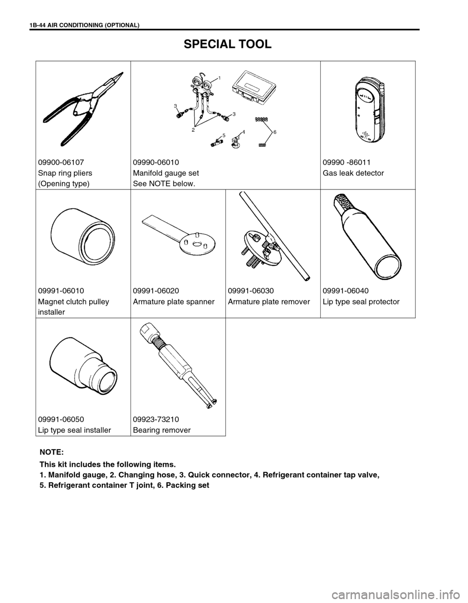
SPECIAL TOOL
09900-06107 09990-06010 09990 -86011
Snap ring pliers
(Opening type)Manifold gauge set
See NOTE below.Gas leak detector
09991-06010 09991-06020 09991-06030 09991-06040
Magnet clutch pulley
installerArmature plate spanner Armature plate remover Lip type seal protector
09991-06050 09923-73210
Lip type seal installer Bearing remover
NOTE:
This kit includes the following items.
1. Manifold gauge, 2. Changing hose, 3. Quick connector, 4. Refrigerant container tap valve,
5. Refrigerant container T joint, 6. Packing set
Page 261 of 698
4A-8 FRONT DRIVE SHAFT
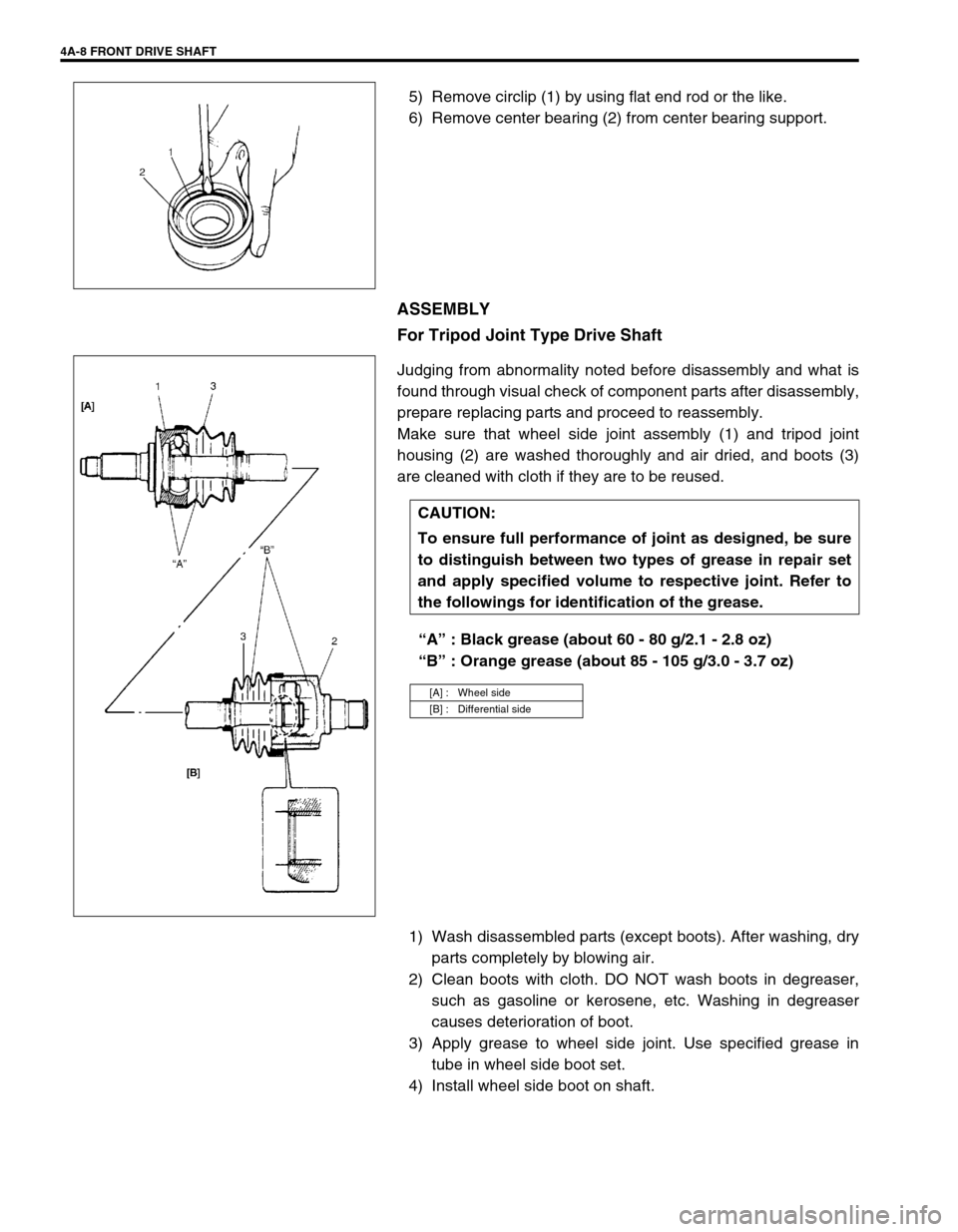
5) Remove circlip (1) by using flat end rod or the like.
6) Remove center bearing (2) from center bearing support.
ASSEMBLY
For Tripod Joint Type Drive Shaft
Judging from abnormality noted before disassembly and what is
found through visual check of component parts after disassembly,
prepare replacing parts and proceed to reassembly.
Make sure that wheel side joint assembly (1) and tripod joint
housing (2) are washed thoroughly and air dried, and boots (3)
are cleaned with cloth if they are to be reused.
“A” : Black grease (about 60 - 80 g/2.1 - 2.8 oz)
“B” : Orange grease (about 85 - 105 g/3.0 - 3.7 oz)
1) Wash disassembled parts (except boots). After washing, dry
parts completely by blowing air.
2) Clean boots with cloth. DO NOT wash boots in degreaser,
such as gasoline or kerosene, etc. Washing in degreaser
causes deterioration of boot.
3) Apply grease to wheel side joint. Use specified grease in
tube in wheel side boot set.
4) Install wheel side boot on shaft.
CAUTION:
To ensure full performance of joint as designed, be sure
to distinguish between two types of grease in repair set
and apply specified volume to respective joint. Refer to
the followings for identification of the grease.
[A] : Wheel side
[B] : Differential side
Page 264 of 698
FRONT DRIVE SHAFT 4A-11
For DOJ Type Drive Shaft
Judging from abnormality noted before disassembly and what is
found though visual check of component parts after disassembly,
prepare replacing parts and proceed to reassembly.
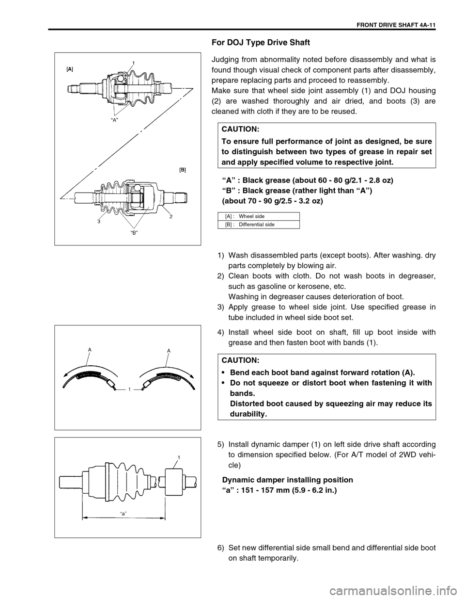
Make sure that wheel side joint assembly (1) and DOJ housing
(2) are washed thoroughly and air dried, and boots (3) are
cleaned with cloth if they are to be reused.
“A” : Black grease (about 60 - 80 g/2.1 - 2.8 oz)
“B” : Black grease (rather light than “A”)
(about 70 - 90 g/2.5 - 3.2 oz)
1) Wash disassembled parts (except boots). After washing. dry
parts completely by blowing air.
2) Clean boots with cloth. Do not wash boots in degreaser,
such as gasoline or kerosene, etc.
Washing in degreaser causes deterioration of boot.
3) Apply grease to wheel side joint. Use specified grease in
tube included in wheel side boot set.
4) Install wheel side boot on shaft, fill up boot inside with
grease and then fasten boot with bands (1).
5) Install dynamic damper (1) on left side drive shaft according
to dimension specified below. (For A/T model of 2WD vehi-
cle)
Dynamic damper installing position
“a” : 151 - 157 mm (5.9 - 6.2 in.)
6) Set new differential side small bend and differential side boot
on shaft temporarily. CAUTION:
To ensure full performance of joint as designed, be sure
to distinguish between two types of grease in repair set
and apply specified volume to respective joint.
[A] : Wheel side
[B] : Differential side
CAUTION:
Bend each boot band against forward rotation (A).
Do not squeeze or distort boot when fastening it with
bands.
Distorted boot caused by squeezing air may reduce its
durability.
Page 374 of 698
ENGINE GENERAL INFORMATION AND DIAGNOSIS 6-5
PRECAUTION ON FUEL SYSTEM SERVICE
Work must be done with no smoking, in a well-ventilated
area and away from any open flames.
As fuel feed line (between fuel pump and fuel delivery pipe)
is still under high fuel pressure even after engine was
stopped, loosening or disconnecting fuel feed line directly
may cause dangerous spout of fuel to occur where loosened
or disconnected.
Before loosening or disconnecting fuel feed line, make sure
to release fuel pressure according to “FUEL PRESSURE
RELIEF PROCEDURE”. A small amount of fuel may be
released after the fuel line is disconnected. In order to
reduce the chance of personal injury, cover the fitting to be
disconnected with a shop cloth. Put that cloth in an approved
container when disconnection is completed.
Never run engine with fuel pump relay disconnected when
engine and exhaust system are hot.
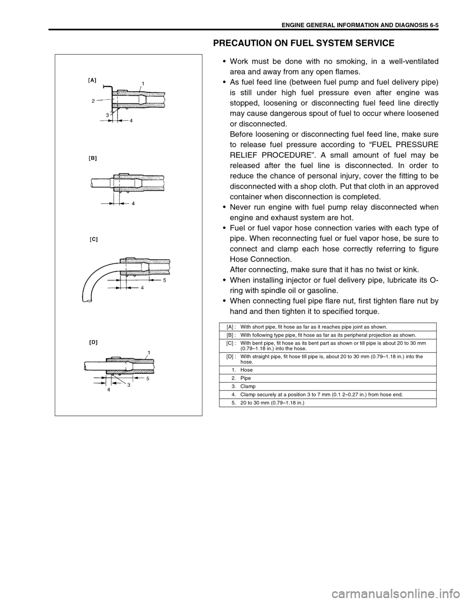
Fuel or fuel vapor hose connection varies with each type of
pipe. When reconnecting fuel or fuel vapor hose, be sure to
connect and clamp each hose correctly referring to figure
Hose Connection.
After connecting, make sure that it has no twist or kink.
When installing injector or fuel delivery pipe, lubricate its O-
ring with spindle oil or gasoline.
When connecting fuel pipe flare nut, first tighten flare nut by
hand and then tighten it to specified torque.
[A] : With short pipe, fit hose as far as it reaches pipe joint as shown.
[B] : With following type pipe, fit hose as far as its peripheral projection as shown.
[C] : With bent pipe, fit hose as its bent part as shown or till pipe is about 20 to 30 mm
(0.79–1.18 in.) into the hose.
[D] : With straight pipe, fit hose till pipe is, about 20 to 30 mm (0.79–1.18 in.) into the
hose.
1. Hose
2. Pipe
3. Clamp
4. Clamp securely at a position 3 to 7 mm (0.1 2–0.27 in.) from hose end.
5. 20 to 30 mm (0.79–1.18 in.)
Page 463 of 698
6-94 ENGINE GENERAL INFORMATION AND DIAGNOSIS
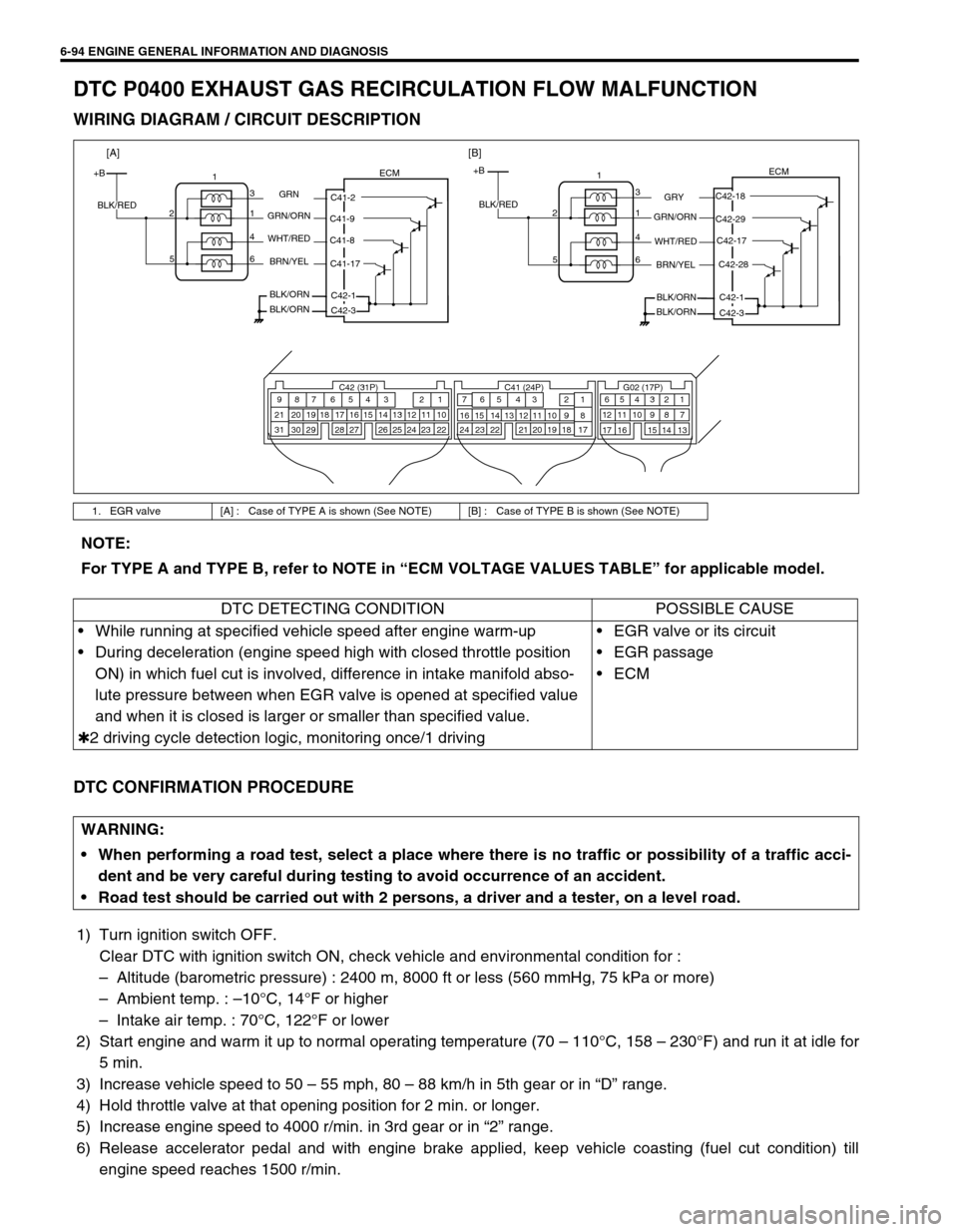
DTC P0400 EXHAUST GAS RECIRCULATION FLOW MALFUNCTION
WIRING DIAGRAM / CIRCUIT DESCRIPTION
DTC CONFIRMATION PROCEDURE
1) Turn ignition switch OFF.
Clear DTC with ignition switch ON, check vehicle and environmental condition for :
–Altitude (barometric pressure) : 2400 m, 8000 ft or less (560 mmHg, 75 kPa or more)
–Ambient temp. : –10°C, 14°F or higher
–Intake air temp. : 70°C, 122°F or lower
2) Start engine and warm it up to normal operating temperature (70 – 110°C, 158 – 230°F) and run it at idle for
5 min.
3) Increase vehicle speed to 50 – 55 mph, 80 – 88 km/h in 5th gear or in “D” range.
4) Hold throttle valve at that opening position for 2 min. or longer.
5) Increase engine speed to 4000 r/min. in 3rd gear or in “2” range.
6) Release accelerator pedal and with engine brake applied, keep vehicle coasting (fuel cut condition) till
engine speed reaches 1500 r/min.
1. EGR valve [A] : Case of TYPE A is shown (See NOTE) [B] : Case of TYPE B is shown (See NOTE)
C42 (31P) C41 (24P) G02 (17P)1 2 3 4 5 6 7 8 9
10 11 12 13 14 15 16 17 18 19 20 21
22 23 24 25 26 28 27 29 30 315 6
1 2 3 4 5 6 7
11 12
9 10 11 13 12 14 15 16
16 171 2
7 8
13 14 3 4
9 10
15 17 188
19 20 21 22 23 24
+BECM
C42-18
C42-29
C42-28 C42-17
C42-1
GRY
GRN/ORN
WHT/RED
C42-3 BRN/YEL
BLK/ORN
BLK/ORN BLK/RED1
3
1 2
4
6 5
+BECM
C41-2
C41-9
C41-17 C41-8
C42-1
GRN
GRN/ORN
WHT/RED
C42-3 BRN/YEL
BLK/ORN
BLK/ORN BLK/RED1
3
1 2
4
6 5
[A][B]
NOTE:
For TYPE A and TYPE B, refer to NOTE in “ECM VOLTAGE VALUES TABLE” for applicable model.
DTC DETECTING CONDITION POSSIBLE CAUSE
While running at specified vehicle speed after engine warm-up
During deceleration (engine speed high with closed throttle position
ON) in which fuel cut is involved, difference in intake manifold abso-
lute pressure between when EGR valve is opened at specified value
and when it is closed is larger or smaller than specified value.
✱2 driving cycle detection logic, monitoring once/1 drivingEGR valve or its circuit
EGR passage
ECM
WARNING:
When performing a road test, select a place where there is no traffic or possibility of a traffic acci-
dent and be very careful during testing to avoid occurrence of an accident.
Road test should be carried out with 2 persons, a driver and a tester, on a level road.
Page 503 of 698
6A1-2 ENGINE MECHANICAL (M13 ENGINE)
GENERAL DESCRIPTION
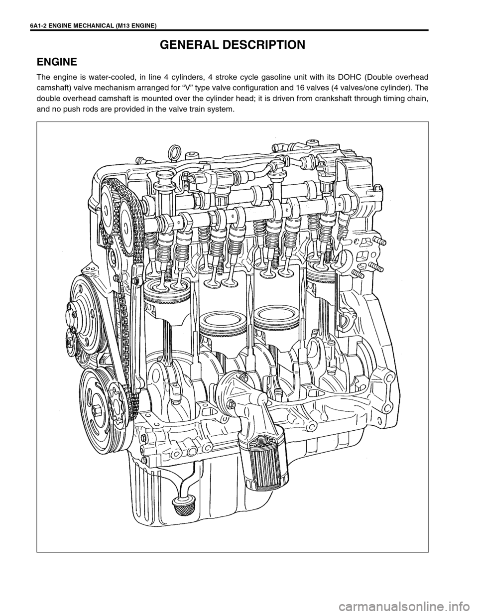
ENGINE
The engine is water-cooled, in line 4 cylinders, 4 stroke cycle gasoline unit with its DOHC (Double overhead
camshaft) valve mechanism arranged for “V” type valve configuration and 16 valves (4 valves/one cylinder). The
double overhead camshaft is mounted over the cylinder head; it is driven from crankshaft through timing chain,
and no push rods are provided in the valve train system.
Page 553 of 698
6A1-52 ENGINE MECHANICAL (M13 ENGINE)
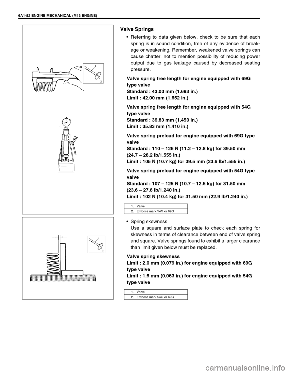
Valve Springs
Referring to data given below, check to be sure that each
spring is in sound condition, free of any evidence of break-
age or weakening. Remember, weakened valve springs can
cause chatter, not to mention possibility of reducing power
output due to gas leakage caused by decreased seating
pressure.
Valve spring free length for engine equipped with 69G
type valve
Standard : 43.00 mm (1.693 in.)
Limit : 42.00 mm (1.652 in.)
Valve spring free length for engine equipped with 54G
type valve
Standard : 36.83 mm (1.450 in.)
Limit : 35.83 mm (1.410 in.)
Valve spring preload for engine equipped with 69G type
valve
Standard : 110 – 126 N (11.2 – 12.8 kg) for 39.50 mm
(24.7 – 28.2 lb/1.555 in.)
Limit : 105 N (10.7 kg) for 39.5 mm (23.6 lb/1.555 in.)
Valve spring preload for engine equipped with 54G type
valve
Standard : 107 – 125 N (10.7 – 12.5 kg) for 31.50 mm
(23.6 – 27.6 lb/1.240 in.)
Limit : 102 N (10.4 kg) for 31.50 mm (22.9 lb/1.240 in.)
Spring skewness:
Use a square and surface plate to check each spring for
skewness in terms of clearance between end of valve spring
and square. Valve springs found to exhibit a larger clearance
than limit given below must be replaced.
Valve spring skewness
Limit : 2.0 mm (0.079 in.) for engine equipped with 69G
type valve
Limit : 1.6 mm (0.063 in.) for engine equipped with 54G
type valve
1. Valve
2. Emboss mark 54G or 69G
1. Valve
2. Emboss mark 54G or 69G
Page 610 of 698
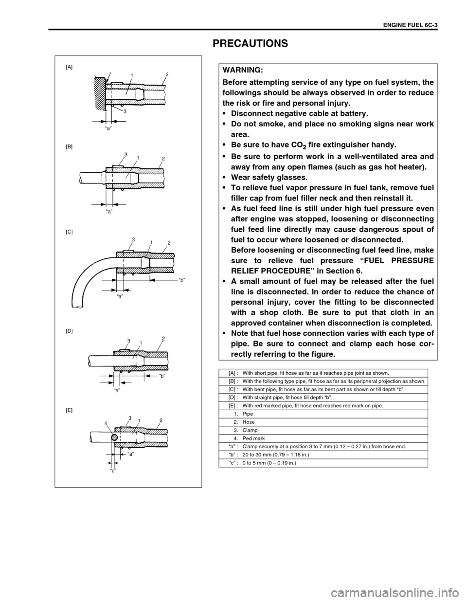
ENGINE FUEL 6C-3
PRECAUTIONS
WARNING:
Before attempting service of any type on fuel system, the
followings should be always observed in order to reduce
the risk or fire and personal injury.
Disconnect negative cable at battery.
Do not smoke, and place no smoking signs near work
area.
Be sure to have CO
2 fire extinguisher handy.
Be sure to perform work in a well-ventilated area and
away from any open flames (such as gas hot heater).
Wear safety glasses.
To relieve fuel vapor pressure in fuel tank, remove fuel
filler cap from fuel filler neck and then reinstall it.
As fuel feed line is still under high fuel pressure even
after engine was stopped, loosening or disconnecting
fuel feed line directly may cause dangerous spout of
fuel to occur where loosened or disconnected.
Before loosening or disconnecting fuel feed line, make
sure to relieve fuel pressure “FUEL PRESSURE
RELIEF PROCEDURE” in Section 6.
A small amount of fuel may be released after the fuel
line is disconnected. In order to reduce the chance of
personal injury, cover the fitting to be disconnected
with a shop cloth. Be sure to put that cloth in an
approved container when disconnection is completed.
Note that fuel hose connection varies with each type of
pipe. Be sure to connect and clamp each hose cor-
rectly referring to the figure.
[A] : With short pipe, fit hose as far as it reaches pipe joint as shown.
[B] : With the following type pipe, fit hose as far as its peripheral projection as shown.
[C] : With bent pipe, fit hose as far as its bent part as shown or till depth “b”.
[D] : With straight pipe, fit hose till depth “b”.
[E] : With red marked pipe, fit hose end reaches red mark on pipe.
1. Pipe
2. Hose
3. Clamp
4. Ped mark
“a” : Clamp securely at a position 3 to 7 mm (0.12 – 0.27 in.) from hose end.
“b” : 20 to 30 mm (0.79 – 1.18 in.)
“c” : 0 to 5 mm (0 – 0.19 in.)
Page 667 of 698
IGNITION SYSTEM (ELECTRONIC IGNITION SYSTEM 6F1-5
ON-VEHICLE SERVICE
IGNITION SPARK TEST
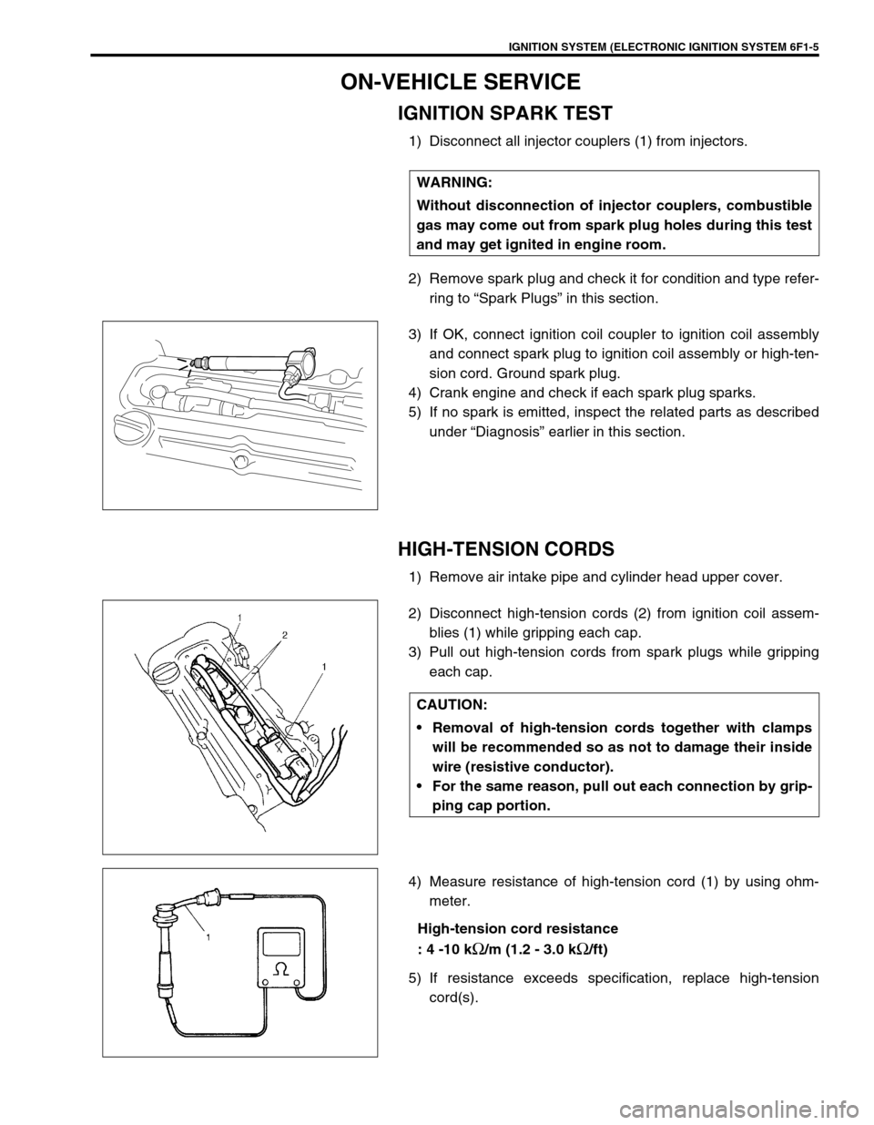
1) Disconnect all injector couplers (1) from injectors.
2) Remove spark plug and check it for condition and type refer-
ring to “Spark Plugs” in this section.
3) If OK, connect ignition coil coupler to ignition coil assembly
and connect spark plug to ignition coil assembly or high-ten-
sion cord. Ground spark plug.
4) Crank engine and check if each spark plug sparks.
5) If no spark is emitted, inspect the related parts as described
under “Diagnosis” earlier in this section.
HIGH-TENSION CORDS
1) Remove air intake pipe and cylinder head upper cover.
2) Disconnect high-tension cords (2) from ignition coil assem-
blies (1) while gripping each cap.
3) Pull out high-tension cords from spark plugs while gripping
each cap.
4) Measure resistance of high-tension cord (1) by using ohm-
meter.
High-tension cord resistance
: 4 -10 k
Ω/m (1.2 - 3.0 kΩ/ft)
5) If resistance exceeds specification, replace high-tension
cord(s). WARNING:
Without disconnection of injector couplers, combustible
gas may come out from spark plug holes during this test
and may get ignited in engine room.
CAUTION:
Removal of high-tension cords together with clamps
will be recommended so as not to damage their inside
wire (resistive conductor).
For the same reason, pull out each connection by grip-
ping cap portion.